CN216470579U - Automatic material device that changes of integrated circuit board production line - Google Patents
Automatic material device that changes of integrated circuit board production line Download PDFInfo
- Publication number
- CN216470579U CN216470579U CN202123101164.8U CN202123101164U CN216470579U CN 216470579 U CN216470579 U CN 216470579U CN 202123101164 U CN202123101164 U CN 202123101164U CN 216470579 U CN216470579 U CN 216470579U
- Authority
- CN
- China
- Prior art keywords
- baffle
- circuit board
- integrated circuit
- production line
- motor
- Prior art date
- Legal status (The legal status is an assumption and is not a legal conclusion. Google has not performed a legal analysis and makes no representation as to the accuracy of the status listed.)
- Active
Links
Images

Landscapes
- Automatic Assembly (AREA)
Abstract
The utility model discloses an automatic material device that changes of integrated circuit board production line relates to electrical components technical field. The utility model discloses a first baffle and adjustable fender, symmetrical connection has the ear seat about one side surface of first baffle, and run through connection has the connecting axle on the hollow shaft that one side surface middle part of adjustable fender is connected, and both ends rotate with the medial surface of ear seat respectively about the periphery of connecting axle to be connected, and upper surface one side of first baffle is provided with the runner assembly, and the lower surface of first baffle is connected with the U-shaped frame, and the below bilateral symmetry of U-shaped frame is provided with the pneumatic cylinder. The utility model discloses a set up runner assembly, U-shaped frame and pneumatic cylinder, runner assembly's existence for people are through controlling runner assembly adjustment adjustable fender's angle of direction, and then make the device multi-angle change the material, and the existence of U-shaped frame and pneumatic cylinder, make people through controlling the height of pneumatic cylinder adjustment the device, and then promoted the device and be applicable to the assembly line of co-altitude not.
Description
Technical Field
The utility model belongs to the technical field of electrical components, especially, relate to an automatic material device that changes of integrated circuit board production line.
Background
With the continuous development of social science and technology, many electrical equipment appear on the market, and the appearance of the electrical equipment brings convenience to the work and life of people. Wherein, integrated circuit board belongs to one of electrical equipment's subassembly, because there are multiple components and parts on the integrated circuit board for people need assemble integrated circuit board on the assembly line of difference, in order to change integrated circuit board's the direction of transporting, people have set up automatic commentaries on classics material device on the assembly line, the appearance of automatic commentaries on classics material device has reduced the work load when people's adjustment integrated circuit board transports the direction, but it still has following drawback in the in-service use:
1. the guide angle of the automatic material transferring device of the existing integrated circuit board production line can not be adjusted, so that the automatic material transferring device of the existing integrated circuit board production line can only guide materials according to a single guide angle;
2. the height of the automatic material transferring device of the existing integrated circuit board production line can not be adjusted, so that the automatic material transferring device of the existing integrated circuit board production line is suitable for a single-height production line, and the applicability of the automatic material transferring device of the existing integrated circuit board production line is further reduced.
Therefore, the existing automatic material transferring device for the integrated circuit board production line cannot meet the requirements in practical use, so that an improved technology is urgently needed in the market to solve the problems.
SUMMERY OF THE UTILITY MODEL
An object of the utility model is to provide an automatic material device that changes of integrated circuit board production line through setting up runner assembly, U-shaped frame and pneumatic cylinder, has solved the automatic problem that the direction angle that changes the material device of current integrated circuit board production line can not adjust and the suitability is low.
In order to solve the technical problem, the utility model discloses a realize through following technical scheme:
the utility model relates to an automatic material transferring device of an integrated circuit board production line, which comprises a first baffle plate and a movable baffle plate, the upper part and the lower part of the surface of one side of the first baffle plate are symmetrically connected with ear seats, a hollow shaft connected with the middle part of the surface of one side of the movable baffle plate is connected with a connecting shaft in a penetrating way, the upper end and the lower end of the circumferential surface of the connecting shaft are respectively connected with the inner side surface of the ear seat in a rotating way, one side of the upper surface of the first baffle plate is provided with a rotating component, the rotating assembly comprises a second motor, a second rotating shaft and a connecting frame, the upper end surface of the second rotating shaft connected with the upper end surface of the second motor is connected with a circular seat, the upper surface of the round seat is connected with one side of the lower surface of the connecting frame, the other side of the lower surface of the connecting frame is connected with the upper surface of the movable baffle plate, the lower surface of the first baffle is connected with a U-shaped frame, and hydraulic cylinders are symmetrically arranged on the left side and the right side below the U-shaped frame.
Further, upper surface one side of first baffle is connected with the under shed axle, the lower surface of second motor is connected with the second frame, the lower surface of second frame is connected on the upper surface of under shed axle, and specifically, the existence of under shed axle supports the second frame, and then has prevented that the second frame from blockking the rotation of connecting axle, and the existence of second frame is used for connecting under shed axle and second motor.
Further, the upper surface of pneumatic cylinder is connected with the connecting block, the upper surface of going up the connecting block is connected on the lower surface of U-shaped frame, specifically, goes up the existence of connecting block for connect pneumatic cylinder and U-shaped frame.
Further, be provided with the removal subassembly under the pneumatic cylinder, the removal subassembly includes universal caster and square seat, universal caster's upper surface is connected with square seat, square seat's upper surface is connected on the lower surface of the lower connecting block of the lower surface connection of pneumatic cylinder, specifically, square seat's existence for connect pneumatic cylinder and universal caster, universal caster's existence, convenient to use person removes the pneumatic cylinder.
Further, adjustable fender's lower surface is provided with transports the subassembly, it includes conveying belt, drive roll, first support column, driven voller and second support column to transport the subassembly, the periphery outside transmission of drive roll and driven voller is connected with the conveying belt, both ends are rotated with the internal surface upside of first support column respectively about the periphery of drive roll and are connected, both ends are rotated with the internal surface upside of second support column respectively about the periphery of driven voller and are connected, specifically, the existence of drive roll and driven voller for drive the motion area and remove, the existence of conveying belt is used for transporting integrated circuit board, and the existence of first support column is used for supporting the drive roll, the existence of second support column is used for supporting the driven voller.
Further, a terminal surface of drive roll is provided with drive assembly, drive assembly includes connecting seat, first frame, first motor and first pivot, a surface connection of the first frame of a surface connection of first motor is on the surface upside position of first support column, a terminal surface connection of the first pivot of another surface connection of first motor is on a terminal surface of drive roll, specifically, the existence of first frame for connect first motor and first support column, the existence of first motor is used for driving first pivot to rotate, the existence of first pivot is used for driving the drive roll to rotate.
The utility model discloses following beneficial effect has:
1. the utility model is provided with a rotating component, the upper and lower ends of the circumferential surface of a first baffle are respectively connected with ear seats symmetrically, the hollow shaft connected with the middle part of the lateral surface of a movable baffle is connected with a connecting shaft in a penetrating way, the upper and lower ends of the circumferential surface of the connecting shaft are respectively connected with the inner side surface of the ear seats in a rotating way, one side of the upper surface of the first baffle is provided with the rotating component, the rotating component comprises a second motor, a second rotating shaft and a connecting frame, the upper end surface of the second rotating shaft connected with the upper end surface of the second motor is connected with a circular seat, the upper surface of the circular seat is connected with one side position of the lower surface of the connecting frame, the other side of the lower surface of the connecting frame is connected with the upper surface of the movable baffle, the design is adopted, the rotating shaft is driven to rotate by starting the second motor, the connecting frame is driven to rotate, the movable baffle is driven to rotate, and the included angle formed by the first baffle and the movable baffle is adjusted, and then make the user adjust the angle that first baffle and adjustable fender formed according to actual conditions, and then make the integrated circuit board that the motion was taken the area along adjustable fender on entering different assembly lines.
2. The utility model discloses a set up U-shaped frame and pneumatic cylinder structure, the lower surface of first baffle is connected with the U-shaped frame, the below bilateral symmetry of U-shaped frame is provided with the pneumatic cylinder, so design, make the user drive the U-shaped frame through controlling the pneumatic cylinder and reciprocate, and then drive first baffle and reciprocate, and then drive adjustable fender and reciprocate, and then make the device be applicable to the assembly line of co-altitude, and do not need the user to use the bolt to carry out the position locking to the device, and then the person of facilitating the use is to the device's arrangement, and the person of facilitating the use adjusts the device's position.
Drawings
In order to more clearly illustrate the technical solutions of the embodiments of the present invention, the drawings used in the description of the embodiments will be briefly introduced below, and it is obvious that the drawings in the following description are only some embodiments of the present invention, and it is obvious for those skilled in the art that other drawings can be obtained according to these drawings without creative efforts.
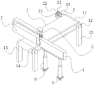
Fig. 1 is a schematic top view of the appearance of the present invention;
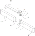
FIG. 2 is a schematic view of the connection between the first baffle and the movable baffle of the present invention;
FIG. 3 is a schematic view of the connection of the rotating assembly, the first baffle and the movable baffle of the present invention;
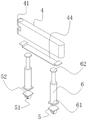
fig. 4 is a schematic connection diagram of the first baffle, the hydraulic cylinder and the moving assembly according to the present invention.
In the drawings, the components represented by the respective reference numerals are listed below:
1. a transport assembly; 11. a conveyor belt; 12. a drive roll; 13. a first support column; 14. a driven roller; 15. a second support column; 2. a drive assembly; 21. a connecting seat; 22. a first base; 23. a first motor; 24. a first rotating shaft; 3. a rotating assembly; 31. a second frame; 32. a second motor; 33. a second rotating shaft; 34. a circular seat; 35. a connecting frame; 4. a first baffle plate; 41. an ear mount; 42. a connecting shaft; 43. a lower opening shaft; 44. a U-shaped frame; 5. a moving assembly; 51. a universal caster; 52. a square base; 6. a hydraulic cylinder; 61. a lower connecting block; 62. an upper connecting block; 7. a movable baffle; 71. a hollow shaft.
Detailed Description
The technical solution in the embodiments of the present invention will be clearly and completely described below with reference to the accompanying drawings in the embodiments of the present invention.
Referring to fig. 1-4, the present invention relates to an automatic transferring device for an integrated circuit board production line, which comprises a first baffle 4 and a movable baffle 7, wherein the upper and lower sides of one side surface of the first baffle 4 are symmetrically connected with ear bases 41, a hollow shaft 71 connected with the middle part of one side surface of the movable baffle 7 is connected with a connecting shaft 42 in a penetrating manner, the upper and lower ends of the circumferential surface of the connecting shaft 42 are respectively connected with the inner side surface of the ear bases 41 in a rotating manner, one side of the upper surface of the first baffle 4 is provided with a rotating assembly 3, the rotating assembly 3 comprises a second motor 32, a second rotating shaft 33 and a connecting frame 35, the upper end surface of the second rotating shaft 33 connected with the upper end surface of the second motor 32 is connected with a circular base 34, the upper surface of the circular base 34 is connected with one side position of the lower surface of the connecting frame 35, the other side of the lower surface of the connecting frame 35 is connected with the upper surface of the movable baffle 7, the lower surface of the first baffle 4 is connected with a U-shaped frame 44, the hydraulic cylinders 6 are symmetrically arranged on the left side and the right side below the U-shaped frame 44, specifically, a user moves the device to a working position, then the user communicates with the hydraulic cylinders 6, then the user starts the hydraulic cylinders 6 by using an external control end, so that the hydraulic cylinders 6 contract, the U-shaped frame 44 is driven to move downwards, the first baffle plate 4 and the movable baffle plate 7 are driven to move downwards, and the lower surfaces of the first baffle plate 4 and the movable baffle plate 7 move downwards to the working position;
next, a plurality of assembly lines are arranged on the conveying belt 11 close to the movable baffle 7 by a user, then the user is communicated with an external power supply of the second motor 32, then the user starts the second motor 32 by using an external control end to drive the second rotating shaft 33 to rotate, drive the circular base 34 to rotate, drive the connecting frame 35 to rotate, drive the connecting shaft 42 to rotate, drive the movable baffle 7 to rotate, and further change an included angle formed by the movable baffle 7 and the first baffle 4 until the movable baffle 7 rotates to the working assembly line;
then, the user starts the first motor 23 to drive the conveying belt 11 to move, and drives the integrated circuit board on the conveying belt 11 to move towards the direction close to the movable baffle 7, and after the integrated circuit board contacts with the movable baffle 7, the integrated circuit board moves towards the assembly line on the lower surface of the movable baffle 7 along the movable baffle 7.
As shown in fig. 3, a lower opening shaft 43 is connected to one side of the upper surface of the first baffle 4, a second motor 32 is connected to the lower surface of the second base 31, and the lower surface of the second base 31 is connected to the upper surface of the lower opening shaft 43, specifically, a user uses an external bolt to lock and connect the second base 31 to the lower opening shaft 43, so that the second motor 32 is stably located on the first baffle 4.
Wherein as shown in fig. 4, the last surface connection of pneumatic cylinder 6 has last connecting block 62, the last surface connection of going up connecting block 62 is on the lower surface of U-shaped frame 44, be provided with removal subassembly 5 under pneumatic cylinder 6, removal subassembly 5 includes casters 51 and square seat 52, casters 51's last surface connection has square seat 52, square seat 52's last surface connection is on the lower surface of the lower connecting block 61 of the lower surface connection of pneumatic cylinder 6, specifically, the user exerts external force to pneumatic cylinder 6, make casters 51 roll, drive square seat 52 and remove, it removes to drive pneumatic cylinder 6, it removes to drive connecting block 62, it removes to drive U-shaped frame 44, it removes to drive first baffle 4 and adjustable fender 7.
As shown in fig. 1, a conveying assembly 1 is disposed on the lower surface of the movable baffle 7, the conveying assembly 1 includes a conveying belt 11, a driving roller 12, a first supporting column 13, a driven roller 14 and a second supporting column 15, the conveying belt 11 is connected to the outer sides of the circumferential surfaces of the driving roller 12 and the driven roller 14 in a transmission manner, the left and right ends of the circumferential surface of the driving roller 12 are respectively rotatably connected to the upper side of the inner surface of the first supporting column 13, the left and right ends of the circumferential surface of the driven roller 14 are respectively rotatably connected to the upper side of the inner surface of the second supporting column 15, a driving assembly 2 is disposed on one end surface of the driving roller 12, the driving assembly 2 includes a connecting seat 21, a first seat 22, a first motor 23 and a first rotating shaft 24, one surface of the first seat 22 connected to one surface of the first motor 23 is connected to the upper side of the outer surface of the first supporting column 13, one end surface of the first rotating shaft 24 connected to the other surface of the first motor 23 is connected to one end surface of the driving roller 12, specifically, the user communicates with the external power supply of the first motor 23, and then, the user starts the first motor 23 using the external control terminal, drives the first rotating shaft 24 to rotate, and drives the driving roller 12 to rotate, so that the conveying belt 11 moves, and further the integrated circuit board located on the conveying belt 11 moves.
The above is only the preferred embodiment of the present invention, and the present invention is not limited thereto, any technical solutions recorded in the foregoing embodiments are modified, and some technical features thereof are replaced with equivalent ones, and any modification, equivalent replacement, and improvement made thereby all belong to the protection scope of the present invention.
Claims (6)
1. The utility model provides an automatic material device that changes of integrated circuit board production line, includes first baffle (4) and adjustable fender (7), its characterized in that: the upper and lower symmetrical connection of a side surface of first baffle (4) has ear seat (41), run through on hollow shaft (71) that a side surface middle part of adjustable fender (7) is connected and be connected with connecting axle (42), both ends rotate with the medial surface of ear seat (41) respectively about the periphery of connecting axle (42) and are connected, upper surface one side of first baffle (4) is provided with runner assembly (3), runner assembly (3) includes second motor (32), second pivot (33) and link (35), the up end of second pivot (33) of the up end connection of second motor (32) is connected with circular seat (34), the upper surface of circular seat (34) is connected on the lower surface one side position of link (35), the lower surface opposite side of link (35) is connected on the upper surface of adjustable fender (7), the lower surface of the first baffle (4) is connected with a U-shaped frame (44), and hydraulic cylinders (6) are arranged below the U-shaped frame (44) in a bilateral symmetry mode.
2. The automatic material transfer device of integrated circuit board production line according to claim 1, wherein one side of the upper surface of the first baffle plate (4) is connected with a lower opening shaft (43), the lower surface of the second motor (32) is connected with a second base (31), and the lower surface of the second base (31) is connected on the upper surface of the lower opening shaft (43).
3. The automatic transfer device of an integrated circuit board production line according to claim 1, wherein the upper surface of the hydraulic cylinder (6) is connected with an upper connecting block (62), and the upper surface of the upper connecting block (62) is connected with the lower surface of the U-shaped frame (44).
4. The automatic material transferring device of the integrated circuit board production line according to claim 3, wherein a moving assembly (5) is arranged right below the hydraulic cylinder (6), the moving assembly (5) comprises a universal caster (51) and a square base (52), the upper surface of the universal caster (51) is connected with the square base (52), and the upper surface of the square base (52) is connected to the lower surface of a lower connecting block (61) connected to the lower surface of the hydraulic cylinder (6).
5. The automatic material transfer device of integrated circuit board production line according to claim 1, characterized in that the lower surface of the movable baffle (7) is provided with a conveying assembly (1), the conveying assembly (1) comprises a conveying belt (11), a driving roller (12), a first supporting column (13), a driven roller (14) and a second supporting column (15), the conveying belt (11) is in transmission connection with the outer side of the circumferential surface of the driving roller (12) and the driven roller (14), the left end and the right end of the circumferential surface of the driving roller (12) are respectively in rotation connection with the upper side of the inner surface of the first supporting column (13), and the left end and the right end of the circumferential surface of the driven roller (14) are respectively in rotation connection with the upper side of the inner surface of the second supporting column (15).
6. The automatic transferring device of the integrated circuit board production line according to claim 5, wherein a driving component (2) is arranged on one end face of the driving roller (12), the driving component (2) comprises a connecting seat (21), a first base (22), a first motor (23) and a first rotating shaft (24), one surface of the first base (22) connected with one surface of the first motor (23) is connected to the upper side position of the outer surface of the first supporting column (13), and one end face of the first rotating shaft (24) connected with the other surface of the first motor (23) is connected to one end face of the driving roller (12).
Priority Applications (1)
| Application Number | Priority Date | Filing Date | Title |
|---|---|---|---|
| CN202123101164.8U CN216470579U (en) | 2021-12-10 | 2021-12-10 | Automatic material device that changes of integrated circuit board production line |
Applications Claiming Priority (1)
| Application Number | Priority Date | Filing Date | Title |
|---|---|---|---|
| CN202123101164.8U CN216470579U (en) | 2021-12-10 | 2021-12-10 | Automatic material device that changes of integrated circuit board production line |
Publications (1)
| Publication Number | Publication Date |
|---|---|
| CN216470579U true CN216470579U (en) | 2022-05-10 |
Family
ID=81422303
Family Applications (1)
| Application Number | Title | Priority Date | Filing Date |
|---|---|---|---|
| CN202123101164.8U Active CN216470579U (en) | 2021-12-10 | 2021-12-10 | Automatic material device that changes of integrated circuit board production line |
Country Status (1)
| Country | Link |
|---|---|
| CN (1) | CN216470579U (en) |
-
2021
- 2021-12-10 CN CN202123101164.8U patent/CN216470579U/en active Active
Similar Documents
| Publication | Publication Date | Title |
|---|---|---|
| CN213864128U (en) | Material conveyor is used in production | |
| CN216470579U (en) | Automatic material device that changes of integrated circuit board production line | |
| CN215796425U (en) | Conveying platform capable of accelerating | |
| CN204526368U (en) | Set type flexible printing machine printing unit | |
| CN210437912U (en) | Machining workpiece conveying device with stabilizing effect | |
| CN210213925U (en) | Rotating mechanism for assembling battery module and regular rotating mechanism | |
| CN214826499U (en) | Annular transport line | |
| CN210392895U (en) | Turning device for guiding | |
| CN213504539U (en) | A loading attachment for making hardware and tools | |
| CN213645459U (en) | Car sheet metal component radian processingequipment | |
| CN218595349U (en) | Automobile parts processes conveyer | |
| CN209998951U (en) | Polishing device for automobile hubs | |
| CN217995763U (en) | Supply chain transfer device | |
| CN218520444U (en) | Conveying mechanism for realizing ceramic tile turning by lifting conveying belt | |
| CN220596177U (en) | Motor processing transposition frame | |
| CN217048676U (en) | Textile fabric transfer device for textile production workshop | |
| CN219097732U (en) | Longitudinal-to-transverse conveyor | |
| CN214030608U (en) | Conveying structure convenient to move | |
| CN210392722U (en) | Screw rod turns to device | |
| CN219708053U (en) | Conveying device for automatic production line | |
| CN213706707U (en) | Double-channel rotary conveying mechanism capable of preventing conveyed materials from slipping | |
| CN219764705U (en) | Filter cloth deviation correcting device of belt filter press | |
| CN220033593U (en) | Folding device is used in tablecloth production | |
| CN210824014U (en) | Lifting automatic conveyor | |
| CN218057124U (en) | Can follow conveyer of transport orbital motion |
Legal Events
| Date | Code | Title | Description |
|---|---|---|---|
| GR01 | Patent grant | ||
| GR01 | Patent grant |