CN216459625U - Rotation spraying device of anticorrosive construction of oil pipeline - Google Patents
Rotation spraying device of anticorrosive construction of oil pipeline Download PDFInfo
- Publication number
- CN216459625U CN216459625U CN202220743875.0U CN202220743875U CN216459625U CN 216459625 U CN216459625 U CN 216459625U CN 202220743875 U CN202220743875 U CN 202220743875U CN 216459625 U CN216459625 U CN 216459625U
- Authority
- CN
- China
- Prior art keywords
- fixed
- driving
- supporting
- mounting frame
- supporting seat
- Prior art date
- Legal status (The legal status is an assumption and is not a legal conclusion. Google has not performed a legal analysis and makes no representation as to the accuracy of the status listed.)
- Active
Links
Images


Abstract
The utility model relates to a rotation spraying device of anticorrosive construction of oil pipeline, including a supporting seat, the one end at supporting seat top is fixed with L type mounting panel, the top sliding connection of supporting seat has the supporting baseplate, be provided with actuating mechanism between supporting baseplate and the supporting seat, the one end at supporting baseplate top is fixed with fixed mounting bracket, the other end at supporting baseplate top can be dismantled and is connected with movable mounting bracket, fixed mounting bracket and movable mounting bracket all rotate to be connected with the axis of rotation, the one end of axis of rotation is fixed with the inserted block, the free end of two inserted blocks joint respectively in the inside at oil pipeline both ends, be provided with on the supporting baseplate between fixed mounting bracket and movable mounting bracket and be used for driving two inserted blocks to carry out rotatory rotary mechanism; the top of the L-shaped mounting plate is fixed with a coating tank, the bottom of the coating tank is communicated with a discharge pipe, the discharge pipe is provided with a booster pump, and one end of the discharge pipe is fixed with a spray head. The spraying device can realize quick and uniform spraying on the surface of the pipeline, and has high spraying efficiency and good quality.
Description
Technical Field
The utility model belongs to the technical field of pipeline anticorrosive spraying equipment, especially, relate to a rotation spraying device of anticorrosive construction of oil pipeline.
Background
The environment that oil pipeline was located in the use often is more complicated, especially buried oil pipeline, because receive effects such as oxygen corrosion, hydrogen sulfide corruption and soil corrosion for a long time, the outer wall of pipeline is corroded the perforation very easily, causes the fluid to leak out, not only makes the transportation interrupt, but also can the polluted environment, probably arouses the conflagration even, causes very big harm. Therefore, the premise of ensuring safe transportation is to carry out anticorrosion construction on the outer wall of the oil pipeline. At present, the outer wall of an oil pipeline is subjected to anticorrosion construction by a treatment mode of spraying an anticorrosion coating on the surface of the oil pipeline by a high-pressure spray gun. When carrying out the spraying to the outer wall of oil pipeline among the prior art, often place oil pipeline vertically, carry out the spraying to the pipeline surface through handheld high-pressure spray gun of workman, the spraying in-process workman need remove around the periphery of pipeline, guarantees that each face of pipeline all is by anticorrosive coating on the spraying. However, this type of spraying has the following disadvantages: (1) in the working process, workers are required to hold the spray gun all the time, the labor intensity is high, and the spraying efficiency is low; (2) the spray gun is manually moved by workers according to experience during spraying, the problem of different spraying thicknesses of the outer wall of the pipeline is easy to occur, and the spraying quality can not be ensured.
SUMMERY OF THE UTILITY MODEL
The utility model aims at providing a rotation spraying device of anticorrosive construction of oil pipeline for there is the technical problem that the spraying is inefficient, the spraying quality is poor in the spraying mode of solving among the prior art.
In order to solve the technical problem, the utility model discloses the technical scheme who adopts is: a rotary spraying device for anticorrosion construction of an oil pipeline is provided, which comprises a horizontally arranged supporting seat, wherein an L-shaped mounting plate extending upwards is fixed at one end of the top of the supporting seat, a horizontally arranged supporting bottom plate is slidably connected to the top of the supporting seat, a driving mechanism for driving the supporting bottom plate to slide along the horizontal direction is arranged between the bottom of the supporting bottom plate and the supporting seat, a vertically upwards arranged fixed mounting frame is fixed at one end of the top of the supporting bottom plate, a vertically upwards arranged movable mounting frame is detachably connected to the other end of the top of the supporting bottom plate, the oil pipeline is horizontally arranged between the fixed mounting frame and the movable mounting frame, a horizontally arranged rotating shaft is rotatably connected to the fixed mounting frame and the movable mounting frame through bearings, an horizontally arranged insert block is fixed at one end of the rotating shaft, the insert block is of a cylindrical structure, and the free ends of the two insert blocks are respectively clamped inside two ends of the oil pipeline, a rotating mechanism for driving the two inserting blocks to rotate is arranged on the supporting bottom plate between the fixed mounting frame and the movable mounting frame; the rotating mechanism comprises two symmetrically arranged mounting seats, a first hydraulic oil cylinder horizontally arranged is fixed between the two mounting seats, two ends of the top of one mounting seat are detachably connected with a driving wheel mounting frame and a driven wheel mounting frame respectively, two ends of the top of the other mounting seat are detachably connected with the driven wheel mounting frame, a plurality of driving wheels arranged at intervals are sequentially and rotatably connected onto the driving wheel mounting frame from top to bottom, the outer wall of each driving wheel is attached to the outer wall of the insert block, a plurality of driven wheels arranged at intervals are sequentially and rotatably connected onto the driven wheel mounting frame from top to bottom, the outer wall of each driven wheel is attached to the outer wall of the insert block, a first driving motor is fixed at a position, close to the driving wheel mounting frame, on the supporting bottom plate, and an output shaft of the first driving motor is in transmission connection with a wheel shaft of one driving wheel through a transmission mechanism; the top of L type mounting panel is fixed with scribbles the workbin, and the bottom intercommunication of scribbling the workbin has the discharging pipe, is provided with the booster pump on the discharging pipe, and the discharging pipe deviates from the below that the one end of scribbling the workbin extends to L type mounting panel and is fixed with the shower nozzle, and the shower nozzle is located oil pipeline's top.
Preferably, the driving mechanism comprises a second driving motor, the second driving motor is fixed on the outer wall of one end of the supporting seat, an installation cavity with an upward opening is arranged in the supporting seat along the length direction of the supporting seat, a horizontally arranged lead screw is rotatably connected to the middle position in the installation cavity, the lead screw extends along the length direction of the supporting seat, one end of the lead screw penetrates through the side wall of the supporting seat and is in transmission connection with an output shaft of the second driving motor through a coupler, two symmetrically arranged guide rods are fixedly connected in the installation cavity at two sides of the lead screw and are arranged in parallel with the lead screw, a sliding sleeve is fixedly connected to the middle position at the bottom of the supporting bottom plate, a threaded long hole penetrating through the sliding sleeve is arranged in the sliding sleeve, the sliding sleeve is in threaded connection with the outside of the lead screw, two symmetrically arranged sliding blocks matched with the guide rods are fixed at the bottom of the supporting bottom plate at two sides of the sliding sleeve, and are in a strip shape and extend along the length direction of the supporting bottom plate, the inside guiding hole that runs through the slider of seting up of slider, the slider passes through guiding hole sliding connection outside at the guide bar.
Preferably, an air heater is fixed at the top of the L-shaped mounting plate, an air outlet end of the air heater is communicated with an air outlet pipe, one end of the air outlet pipe, which is far away from the air heater, extends to the lower part of the L-shaped mounting plate and is fixed with a wind collecting cover, the wind collecting cover is in a cone bucket-shaped structure with a large bottom end and a small top end, and the wind collecting cover is positioned above the oil pipeline.
Preferably, a second hydraulic cylinder which is vertically arranged downwards is fixed at the bottom of the L-shaped mounting plate, and a horizontally arranged cleaning brush is fixed at the bottom of a piston rod of the second hydraulic cylinder.
Preferably, the inserted block is including being cylindric first connecting portion and being the second connecting portion of circular truncated cone structure, first connecting portion and second connecting portion an organic whole connection, the outer wall of action wheel, the outer wall from the driving wheel all laminate mutually with the outer wall of first connecting portion, the one end joint that the second connecting portion deviate from first connecting portion is inside oil pipeline, the external diameter that is located the outside second connecting portion of oil pipeline is greater than the external diameter that is located the inside second connecting portion of oil pipeline.
Preferably, the longitudinal section of movable mounting bracket is type of protruding, and the shaft hole that is used for installing the axis of rotation is offered to movable mounting bracket's intermediate position, and the screw hole that the symmetry set up is offered at the both ends of movable mounting bracket bottom, and the top of supporting baseplate set up the even interval of multiunit and with screw hole matched with screw thread blind hole on along the horizontal direction, screw hole female connection has fixing bolt, and fixing bolt's bottom runs through screw hole and threaded connection inside the screw thread blind hole.
Preferably, the transmission mechanism comprises a speed reducer arranged at an interval with the first driving motor, an output shaft of the first driving motor is in transmission connection with an input shaft of the speed reducer through a coupler, a driving sprocket is fixedly sleeved on the output shaft of the speed reducer, a driven sprocket is fixedly sleeved on a wheel shaft of one of the driving wheels, and the driving sprocket is in transmission connection with the driven sprocket through a transmission chain.
The utility model has the advantages that: structural design is reasonable, installation convenient to use, the cost of manufacture is low, through setting up the supporting seat, supporting baseplate, actuating mechanism, fixed mounting bracket, movable mounting bracket, inserted block and rotary mechanism, in use, through fixed mounting bracket, movable mounting bracket, the inserted block realizes that the centre gripping to oil pipeline is fixed, realize the rotation of oil pipeline through rotary mechanism, thereby realize the autogiration spraying of oil pipeline, and realize oil pipeline's motion at the horizontal direction through actuating mechanism, it can be even by the spraying to guarantee the surface homoenergetic of whole oil pipeline, compare with the spraying mode that traditional dependence workman handheld high-pressure spray gun carries out the spraying to oil pipeline surface, degree of automation is high, use manpower sparingly, the spraying is efficient, and can guarantee that oil pipeline surface spraying is even, avoid appearing the problem that spraying thickness differs, the quality of spraying is improved.
Drawings
Fig. 1 is a schematic structural view of the present invention;
FIG. 2 is a schematic structural view of the supporting base plate cooperating with the rotating mechanism;
FIG. 3 is a schematic structural view of the rotating mechanism;
FIG. 4 is a schematic structural view of the transmission mechanism connected to the first driving motor;
FIG. 5 is a schematic view of a structure of the connection between the driving wheel mounting frame and the mounting seat;
FIG. 6 is a schematic structural view of the connection between the driven wheel mounting bracket and the mounting seat;
FIG. 7 is a cross-sectional view of the flexible mount;
FIG. 8 is a schematic view of the connection between the supporting base and the supporting base plate;
FIG. 9 is a schematic view of the internal structure of the support base;
FIG. 10 is a schematic structural view of a support base;
FIG. 11 is a schematic structural view of the connection between the sliding sleeve and the supporting base plate;
fig. 12 is a schematic structural view of the connection of the slider and the supporting base plate.
Reference numerals: 1-supporting seat, 2-L-shaped mounting plate, 3-supporting base plate, 4-fixed mounting frame, 5-movable mounting frame, 6-oil pipeline, 7-rotating shaft, 8-insert block, 9-shaft hole, 10-threaded hole, 11-threaded blind hole, 12-fixing bolt, 13-mounting seat, 14-first hydraulic oil cylinder, 15-driving wheel mounting frame, 16-driven wheel mounting frame, 17-driving wheel, 18-driven wheel, 19-first connecting part, 20-second connecting part, 21-first driving motor, 22-speed reducer, 23-driving chain wheel, 24-driven chain wheel, 25-conveying chain, 26-coating box, 27-discharging pipe, 28-booster pump, 29-nozzle, 30-second driving motor, 31-mounting cavity, 32-lead screw, 33-guide rod, 34-sliding sleeve, 35-threaded long hole, 36-sliding block, 37-guide hole, 38-hot air blower, 39-air outlet pipe, 39-oil outlet pipe, 40-air gathering cover, 41-second hydraulic oil cylinder, 42-cleaning brush.
Detailed Description
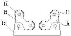
As shown in fig. 1, the utility model discloses a supporting seat 1 that the level set up, the one end at supporting seat 1 top is fixed with the L type mounting panel 2 that upwards extends, and supporting seat 1's top sliding connection has the supporting baseplate 3 that the level set up, is provided with between supporting baseplate 3's bottom and supporting seat 1 to be used for driving supporting baseplate 3 and carries out gliding actuating mechanism along the horizontal direction. As shown in fig. 2, a fixed mounting frame 4 is fixed at one end of the top of the supporting base plate 3 and vertically arranged upwards, and a movable mounting frame 5 is detachably connected at the other end of the top of the supporting base plate 3 and vertically arranged upwards. Oil pipeline 6 horizontal installation is between fixed mounting bracket 4 and movable mounting bracket 5, all rotates the axis of rotation 7 that is connected with the level setting through the bearing on fixed mounting bracket 4 and the movable mounting bracket 5, and the one end of axis of rotation 7 is fixed with the inserted block 8 that the level set up, and inserted block 8 is cylindrical structure, and the free end difference joint of two inserted blocks 8 is in the inside at oil pipeline 6 both ends. As shown in fig. 7, the longitudinal section of the movable mounting frame 5 is in a convex shape, the shaft hole 9 for installing the rotating shaft 7 is provided at the middle position of the movable mounting frame 5, the two ends of the bottom of the movable mounting frame 5 are provided with threaded holes 10 symmetrically arranged, as shown in fig. 8, the top of the supporting bottom plate 3 is provided with a plurality of groups of threaded blind holes 11 uniformly arranged at intervals in the horizontal direction and matched with the threaded holes 10, the threaded holes 10 are internally connected with fixing bolts 12, and the bottom ends of the fixing bolts 12 penetrate through the threaded holes 10 and are connected inside the threaded blind holes 11. A rotating mechanism for driving the two inserting blocks 8 to rotate is arranged on the supporting bottom plate 3 between the fixed mounting frame 4 and the movable mounting frame 5. As shown in fig. 3, the rotating mechanism includes two symmetrically arranged mounting seats 13, a first hydraulic cylinder 14 horizontally arranged is fixed between the two mounting seats 13, and the distance between the two mounting seats 13 is adjusted by the first hydraulic cylinder 14, so as to meet the requirement of spraying oil pipelines 6 with different lengths. As shown in fig. 5 and 6, the two ends of the top of one of the mounting seats 13 are detachably connected with a driving wheel mounting rack 15 and a driven wheel mounting rack 16 respectively, the two ends of the top of the other one of the mounting seats 13 are detachably connected with the driven wheel mounting rack 16, the driving wheels 17 arranged at a plurality of intervals are sequentially and rotatably connected to the driving wheel mounting rack 15 from top to bottom, as shown in fig. 2, the outer wall of each driving wheel 17 is attached to the outer wall of the insert block 8, the driven wheels 18 arranged at a plurality of intervals are sequentially and rotatably connected to the driving wheel mounting rack 16 from top to bottom, and the outer wall of each driven wheel 18 is attached to the outer wall of the insert block 8. In the present embodiment, the number of the driving pulleys 17 is two, but the number of the driving pulleys 17 is not limited to two, and may be two or more. The number of the driven wheels 18 mounted on each driven wheel mounting bracket 16 is two, but is not limited to two, and may be two or more. As shown in fig. 2, the insert block 8 includes a first connecting portion 19 having a cylindrical shape and a second connecting portion 20 having a truncated cone structure, the first connecting portion 19 is integrally connected to the second connecting portion 20, the outer wall of the driving wheel 17 and the outer wall of the driven wheel 18 are both attached to the outer wall of the first connecting portion 19, one end of the second connecting portion 20 departing from the first connecting portion 19 is clamped inside the oil pipeline 6, and the outer diameter of the second connecting portion 20 located outside the oil pipeline 6 is greater than the outer diameter of the second connecting portion 20 located inside the oil pipeline 6. A first driving motor 21 is fixed on the supporting base plate 3 at a position close to the driving wheel mounting frame 15, and an output shaft of the first driving motor 21 is in transmission connection with a wheel shaft of one of the driving wheels 17 through a transmission mechanism. As shown in fig. 4, the transmission mechanism includes a speed reducer 22 spaced apart from the first driving motor 21, an output shaft of the first driving motor 21 is connected to an input shaft of the speed reducer 22 through a coupling, a driving sprocket 23 is fixedly sleeved on the output shaft of the speed reducer 22, as shown in fig. 2, a driven sprocket 24 is fixedly sleeved on a wheel shaft of one of the driving wheels 17, and the driving sprocket 23 is connected to the driven sprocket 24 through a transmission chain 25. A paint tank 26 is fixed on the top of the L-shaped mounting plate 2, a discharge pipe 27 is communicated with the bottom of the paint tank 26, a booster pump 28 is arranged on the discharge pipe 27, one end of the discharge pipe 27, which is far away from the paint tank 26, extends to the lower part of the L-shaped mounting plate 2 and is fixed with a spray head 29, and the spray head 29 is positioned above the oil pipeline 6.
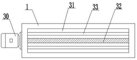
As shown in fig. 8 and 9, the driving mechanism includes a second driving motor 30, the second driving motor 30 is fixed on the outer wall of one end of the supporting seat 1, an installation cavity 31 with an upward opening is formed inside the supporting seat 1 along the length direction of the supporting seat, a lead screw 32 horizontally arranged is rotatably connected to the middle position inside the installation cavity 31, the lead screw 32 extends along the length direction of the supporting seat 1, one end of the lead screw 32 penetrates through the side wall of the supporting seat 1 and is in transmission connection with the output shaft of the second driving motor 30 through a coupler, two guide rods 33 symmetrically arranged are fixedly connected inside the installation cavity 31 on two sides of the lead screw 32, and the guide rods 33 are parallel to the lead screw 32. As shown in fig. 10 and 11, a sliding sleeve 34 is fixedly connected to the middle position of the bottom of the supporting base plate 3, a threaded long hole 35 penetrating through the sliding sleeve 34 is formed inside the sliding sleeve 34, the sliding sleeve 34 is connected to the outside of the screw rod 32 in a threaded manner, two sliding blocks 36 which are symmetrically arranged and matched with the guide rod 33 are fixed to the bottom of the supporting base plate 3 on two sides of the sliding sleeve 34, as shown in fig. 12, each sliding block 36 is long and extends along the length direction of the supporting base plate 3, a guide hole 37 penetrating through the sliding block 36 is formed inside the sliding block 36, and the sliding block 36 is slidably connected to the outside of the guide rod 33 through the guide hole 37.
As shown in fig. 1, an air heater 38 is fixed at the top of the L-shaped mounting plate 2, an air outlet pipe 39 is communicated with an air outlet end of the air heater 38, one end of the air outlet pipe 39 departing from the air heater 38 extends to the lower part of the L-shaped mounting plate 2 and is fixed with a wind collecting cover 40, the wind collecting cover 40 is in a cone hopper-shaped structure with a large bottom end and a small top end, and the wind collecting cover 40 is located above the oil pipeline 6. A second hydraulic oil cylinder 41 which is vertically arranged downwards is fixed at the bottom of the L-shaped mounting plate 2, and a cleaning brush 42 which is horizontally arranged is fixed at the bottom of a piston rod of the second hydraulic oil cylinder 41. By arranging the hot air blower 38 and the cleaning brush 42, rust spots, adhesive substances and the like on the surface of the oil pipeline 6 are cleaned by the cleaning brush 42 before spraying, so that the cleanliness of the surface of the oil pipeline 6 is ensured, and the spraying effect is improved. And through setting up air heater 38, can be quick dry anticorrosive paint in the spraying process, improve work efficiency.
The utility model discloses a theory of operation and working process: during the use, as shown in fig. 2, at first with the inside of 6 one ends of oil pipeline of the 8 joint of inserted block of being connected with fixed mounting bracket 4, according to the mounted position of the length adjustment flexible mounting bracket 5 of oil pipeline 6, with the inside of the other 8 joints of inserted block at the oil pipeline 6 other end, utilize fixing bolt 12 to be connected flexible mounting bracket 5 with supporting baseplate 3, two inserted blocks 8 carry out the centre gripping to oil pipeline 6 fixedly. Placing the two mounting seats 13 on the top of the supporting base plate 3, starting the first hydraulic oil cylinder 14, adjusting the distance between the two mounting seats 13, so that the outer walls of the driving wheel 17 and the driven wheel 18 are both attached to the outer wall of the insert block 8, starting the first driving motor 21, and rotating the output shaft of the first driving motor 21 to sequentially drive the speed reducer 22 to work, thereby sequentially driving the driving chain wheel 23, the conveying chain 25 and the driven chain wheel 24 to rotate, and the driven chain wheel 24 driving the driving wheel 17 to rotate, and further sequentially driving the insert block 8 and the oil pipeline 6 to rotate; meanwhile, the second driving motor 30 is started, the second driving motor 30 drives the screw rod 32 to rotate, and the screw rod 32 rotates to drive the supporting bottom plate 3 to horizontally move along the length direction of the supporting seat 1 under the limiting and guiding effects of the two guide rods 33 as the sliding sleeve 34 is in threaded connection with the screw rod 32, so that the oil pipeline 6 moves while rotating; the second hydraulic cylinder 41 is started, the bottom end of the cleaning brush 42 is attached to the outer wall of the oil conveying pipeline 6, the outer wall of the oil conveying pipeline 6 is cleaned, after cleaning is finished, the second hydraulic cylinder 41 is used for driving the cleaning brush 42 to move upwards, the booster pump 28 and the air heater 38 are started, in the process that the oil conveying pipeline 6 rotates and moves, the spray head 29 sprays anti-corrosion paint uniformly on the surface of the oil conveying pipeline 6, and hot air sprayed out of the air heater 38 is sprayed on the surface of the oil conveying pipeline 6 through the air collecting cover 40, so that the paint on the oil conveying pipeline 6 is dried.
The above-mentioned embodiment is right the utility model discloses an explanation, it is not right the utility model discloses a limited, any right the scheme after the simple transform of the utility model all belongs to the protection scope of the utility model.
Claims (7)
1. The utility model provides a rotation spraying device of anticorrosive construction of oil pipeline, includes the supporting seat that the level set up, the one end at supporting seat top is fixed with the L type mounting panel that upwards extends, its characterized in that: the top of the supporting seat is slidably connected with a horizontally arranged supporting bottom plate, a driving mechanism used for driving the supporting bottom plate to slide along the horizontal direction is arranged between the bottom of the supporting bottom plate and the supporting seat, a vertically upward arranged fixed mounting frame is fixed at one end of the top of the supporting bottom plate, a vertically upward arranged movable mounting frame is detachably connected at the other end of the top of the supporting bottom plate, the oil pipeline is horizontally arranged between the fixed mounting frame and the movable mounting frame, a horizontally arranged rotating shaft is rotatably connected to the fixed mounting frame and the movable mounting frame through bearings, horizontally arranged inserting blocks are fixed at one ends of the rotating shaft and are of a cylindrical structure, the free ends of the two inserting blocks are respectively clamped inside two ends of the oil pipeline, and a rotating mechanism used for driving the two inserting blocks to rotate is arranged on the supporting bottom plate between the fixed mounting frame and the movable mounting frame; the rotating mechanism comprises two symmetrically arranged mounting seats, a first hydraulic oil cylinder horizontally arranged is fixed between the two mounting seats, two ends of the top of one mounting seat are detachably connected with a driving wheel mounting frame and a driven wheel mounting frame respectively, two ends of the top of the other mounting seat are detachably connected with the driven wheel mounting frame, a plurality of driving wheels arranged at intervals are sequentially and rotatably connected onto the driving wheel mounting frame from top to bottom, the outer wall of each driving wheel is attached to the outer wall of the insert block, a plurality of driven wheels arranged at intervals are sequentially and rotatably connected onto the driven wheel mounting frame from top to bottom, the outer wall of each driven wheel is attached to the outer wall of the insert block, a first driving motor is fixed at a position, close to the driving wheel mounting frame, on the supporting bottom plate, and an output shaft of the first driving motor is in transmission connection with a wheel shaft of one driving wheel through a transmission mechanism; the top of L type mounting panel is fixed with scribbles the workbin, and the bottom intercommunication of scribbling the workbin has the discharging pipe, is provided with the booster pump on the discharging pipe, and the discharging pipe deviates from the below that the one end of scribbling the workbin extends to L type mounting panel and is fixed with the shower nozzle, and the shower nozzle is located oil pipeline's top.
2. The rotary spraying device for the anticorrosion construction of the oil conveying pipeline according to claim 1, characterized in that: the driving mechanism comprises a second driving motor, the second driving motor is fixed on the outer wall of one end of the supporting seat, an installation cavity with an upward opening is arranged in the supporting seat along the length direction of the supporting seat, a horizontally arranged lead screw is rotatably connected at the middle position in the installation cavity, the lead screw extends along the length direction of the supporting seat, one end of the lead screw penetrates through the side wall of the supporting seat and is in transmission connection with an output shaft of the second driving motor through a coupler, two symmetrically arranged guide rods are fixedly connected in the installation cavity at two sides of the lead screw, the guide rods are arranged in parallel with the lead screw, a sliding sleeve is fixedly connected at the middle position at the bottom of the supporting bottom plate, a threaded long hole penetrating through the sliding sleeve is arranged in the sliding sleeve, the sliding sleeve is in threaded connection with the outside of the lead screw, two symmetrically arranged sliding blocks matched with the guide rods are fixed at the bottom of the supporting bottom plate at two sides of the sliding sleeve, and the sliding blocks are in a long strip shape and extend along the length direction of the supporting bottom plate, the inside guiding hole that runs through the slider of seting up of slider, the slider passes through guiding hole sliding connection outside at the guide bar.
3. The rotary spraying device for the anticorrosion construction of the oil conveying pipeline according to claim 2, characterized in that: the air heater is fixed at the top of the L-shaped mounting plate, an air outlet pipe is communicated with an air outlet end of the air heater, one end, deviating from the air heater, of the air outlet pipe extends to the lower portion of the L-shaped mounting plate and is fixed with a wind collecting cover, the wind collecting cover is of a cone bucket-shaped structure with a large bottom end and a small top end, and the wind collecting cover is located above the oil conveying pipeline.
4. The rotary spraying device for the anticorrosion construction of the oil conveying pipeline according to claim 3, characterized in that: and a second hydraulic cylinder which is vertically arranged downwards is fixed at the bottom of the L-shaped mounting plate, and a horizontally arranged cleaning brush is fixed at the bottom of a piston rod of the second hydraulic cylinder.
5. The rotary spraying device for the anticorrosion construction of the oil conveying pipeline according to claim 3, characterized in that: the inserted block is including being cylindric first connecting portion and being the second connecting portion of circular cone frustum structure, first connecting portion and second connecting portion an organic whole connection, the outer wall of action wheel, all laminate mutually with the outer wall of first connecting portion from the outer wall of driving wheel, the one end joint that the second connecting portion deviate from first connecting portion is inside oil pipeline, the external diameter that is located the outside second connecting portion of oil pipeline is greater than the external diameter that is located the inside second connecting portion of oil pipeline.
6. The rotary spraying device for the anticorrosion construction of the oil conveying pipeline according to claim 3, characterized in that: the longitudinal section of movable mounting bracket is type of protruding, and the shaft hole that is used for installing the axis of rotation is offered to movable mounting bracket's intermediate position, and the screw hole that the symmetry set up is offered at the both ends of movable mounting bracket bottom, and the top of supporting baseplate set up on the horizontal direction multiunit even interval and with screw hole matched with screw thread blind hole, screw hole female connection has fixing bolt, and fixing bolt's bottom runs through screw hole and threaded connection is inside the screw thread blind hole.
7. The rotary spraying device for oil pipeline anticorrosion construction according to any one of claims 1-6, wherein: the transmission mechanism comprises a speed reducer arranged at an interval with a first driving motor, an output shaft of the first driving motor is in transmission connection with an input shaft of the speed reducer through a coupler, a driving chain wheel is fixedly sleeved on the output shaft of the speed reducer, a driven chain wheel is fixedly sleeved on a wheel shaft of one of the driving wheels, and the driving chain wheel is in transmission connection with the driven chain wheel through a transmission chain.
Priority Applications (1)
| Application Number | Priority Date | Filing Date | Title |
|---|---|---|---|
| CN202220743875.0U CN216459625U (en) | 2022-04-01 | 2022-04-01 | Rotation spraying device of anticorrosive construction of oil pipeline |
Applications Claiming Priority (1)
| Application Number | Priority Date | Filing Date | Title |
|---|---|---|---|
| CN202220743875.0U CN216459625U (en) | 2022-04-01 | 2022-04-01 | Rotation spraying device of anticorrosive construction of oil pipeline |
Publications (1)
| Publication Number | Publication Date |
|---|---|
| CN216459625U true CN216459625U (en) | 2022-05-10 |
Family
ID=81433548
Family Applications (1)
| Application Number | Title | Priority Date | Filing Date |
|---|---|---|---|
| CN202220743875.0U Active CN216459625U (en) | 2022-04-01 | 2022-04-01 | Rotation spraying device of anticorrosive construction of oil pipeline |
Country Status (1)
| Country | Link |
|---|---|
| CN (1) | CN216459625U (en) |
Cited By (1)
| Publication number | Priority date | Publication date | Assignee | Title |
|---|---|---|---|---|
| CN116550694A (en) * | 2023-07-10 | 2023-08-08 | 山东蓝色海洋科技股份有限公司 | Cleaning device for anti-corrosion treatment of outer wall of wind power tower |
-
2022
- 2022-04-01 CN CN202220743875.0U patent/CN216459625U/en active Active
Cited By (2)
| Publication number | Priority date | Publication date | Assignee | Title |
|---|---|---|---|---|
| CN116550694A (en) * | 2023-07-10 | 2023-08-08 | 山东蓝色海洋科技股份有限公司 | Cleaning device for anti-corrosion treatment of outer wall of wind power tower |
| CN116550694B (en) * | 2023-07-10 | 2023-09-29 | 山东蓝色海洋科技股份有限公司 | Cleaning device for anti-corrosion treatment of outer wall of wind power tower |
Similar Documents
| Publication | Publication Date | Title |
|---|---|---|
| CN108993796B (en) | Working method of device for uniformly removing rust and spraying paint on pipeline | |
| CN204503415U (en) | A kind of tubing anticorrosion rapid curing device | |
| CN210632367U (en) | Spraying device for surface treatment of steel structural member | |
| CN107999435B (en) | Automatic cleaning machine for bolts | |
| CN216459625U (en) | Rotation spraying device of anticorrosive construction of oil pipeline | |
| CN114308458B (en) | Anticorrosive even coating device of petrochemical equipment tubular heat exchanger | |
| CN206240683U (en) | hand-held surface spraying device | |
| CN112403785A (en) | A rust cleaning paint spraying apparatus for old and useless building girder steel | |
| CN112076918A (en) | Injection apparatus is used in production of anticorrosive heat preservation pipeline | |
| CN202155296U (en) | Automatic inner wall and outer wall coating machine for steel pipe | |
| CN109013086A (en) | A kind of automatic filling paint equipment | |
| CN105944886A (en) | Pipeline spraying device | |
| CN116037372A (en) | Surface treatment device and method for pipeline external corrosion prevention procedure | |
| CN211816417U (en) | Pipe gallery wall body construction equipment | |
| CN210304257U (en) | Anticorrosive spraying device of municipal works I-steel | |
| CN219442163U (en) | Super-huge steel structure surface anti-corrosion coating spraying device | |
| CN220004531U (en) | Anticorrosive spraying equipment of natural gas pipeline | |
| CN214682404U (en) | Pipeline processing device | |
| CN217140802U (en) | High-efficient spraying device of anticorrosive construction of pipeline | |
| CN219580915U (en) | Pipeline surface anticorrosion spraying equipment | |
| CN219785329U (en) | Pipeline anticorrosion brushing device | |
| CN114832995B (en) | Equipment is paintd to daily anticorrosive material of industrial pipeline | |
| CN218854640U (en) | Rust-resistant subassembly in surface for tuber pipe production | |
| CN219880280U (en) | Rust-proof smearing equipment for cutter | |
| CN211989302U (en) | 360-degree hanging spraying device for powder coating of large metal part |
Legal Events
| Date | Code | Title | Description |
|---|---|---|---|
| GR01 | Patent grant | ||
| GR01 | Patent grant |