CN216457606U - A gas cleaning processing apparatus for chemical industry plastics production - Google Patents
A gas cleaning processing apparatus for chemical industry plastics production Download PDFInfo
- Publication number
- CN216457606U CN216457606U CN202220829809.5U CN202220829809U CN216457606U CN 216457606 U CN216457606 U CN 216457606U CN 202220829809 U CN202220829809 U CN 202220829809U CN 216457606 U CN216457606 U CN 216457606U
- Authority
- CN
- China
- Prior art keywords
- fixedly connected
- flue gas
- box
- treatment device
- gas purification
- Prior art date
- Legal status (The legal status is an assumption and is not a legal conclusion. Google has not performed a legal analysis and makes no representation as to the accuracy of the status listed.)
- Active
Links
Images

Abstract
The utility model relates to a gas cleaning equipment technical field discloses a gas cleaning processing apparatus for chemical industry plastics production, including the loading board, the top right side fixedly connected with alignment jig of loading board, the equal sliding connection in both ends inner wall has the slider around the alignment jig, the inboard one end of slider is all rotated and is connected with the resistance axle, the inboard one end difference fixed connection of resistance axle is in the both sides of breathing in the cover, the top rear fixedly connected with servo motor of alignment jig, servo motor's drive end fixedly connected with lead screw. The utility model discloses in, through the water in the water pump extraction rose box and by the blowout of spherical shower nozzle, can wash first filter screen, guarantee the filter effect of first filter screen, improved work efficiency, drive the lead screw through servo motor and rotate, can realize the altitude mixture control of the cover of breathing in, can adjust the angle of the cover of breathing in through rotating the resistance axle, improved the absorption effect of flue gas.
Description
Technical Field
The utility model relates to a gas cleaning equipment technical field especially relates to a gas cleaning processing apparatus for chemical industry plastics production.
Background
Chemical industry, that is, chemical industry, all of which use chemical methods to change the composition or structure of substances or synthesize new substances, belongs to chemical production technology, that is, chemical process, and the obtained products are called chemicals or chemical products, and when the chemical products are produced, a large amount of flue gas is generated, and in order to treat the flue gas, a purification device is needed.
Chinese patent document CN215027084U discloses a flue gas purification device for chemical industry environmental protection, including fixed frame, the middle part fixedly connected with of fixed frame handles the frame, the left side of fixed frame is provided with the air inlet, the tip fixedly connected with tubular metal resonator of air inlet, the tubular metal resonator is located the inside of fixed frame, the utility model relates to an environmental protection technical field. The flue gas purification device for chemical environmental protection achieves the aims of introducing flue gas generated in chemical production into a treatment frame, performing multiple filtration through a first filter screen and a second filter screen, filtering particles in the flue gas, arranging a stirring device, conveniently wiping the filter screens, reducing filter screen blockage, improving the filtering efficiency of the filter screens, arranging a conical collecting plate, conveniently collecting filtered substances, arranging a water inlet and a water outlet, conveniently introducing water into a fixed frame, heating the water by using the waste heat of the flue gas, improving the resource utilization rate and meeting the use requirement, but cleaning the filter screens through the stirring device firstly leads the filter screens to be easy to damage, the service life of the filter screens is reduced, secondly, the cleaning effect is not obvious, smoke dust is difficult to collect or clean, meanwhile, the device has low flexibility of an air inlet, and is inconvenient to adjust the height and the angle of the air inlet according to the position generated by the flue gas, the air suction effect is poor.
SUMMERY OF THE UTILITY MODEL
The utility model aims at solving the defects existing in the prior art and providing a flue gas purification treatment device for chemical plastic production.
In order to achieve the above purpose, the utility model adopts the following technical scheme: a flue gas purification treatment device for chemical plastic production comprises a bearing plate, wherein an adjusting frame is fixedly connected to the right side of the top end of the bearing plate, sliding blocks are connected to the inner walls of the front end and the rear end of the adjusting frame in a sliding manner, one end of the inner side of each sliding block is rotatably connected with a resistance shaft, one end of the inner side of each resistance shaft is fixedly connected to two sides of an air suction cover, a servo motor is fixedly connected to the rear of the top end of the adjusting frame, a lead screw is fixedly connected to the driving end of the servo motor, a purification box is fixedly connected to the top end of the bearing plate, corresponding to the left side of the adjusting frame, the middle part of the inner wall of the purification box is fixedly connected with a first filter screen, a water outlet pipe is fixedly connected to the middle part of the bottom end of the purification box, a filter box is fixedly connected to the bottom end of the water outlet pipe, a circulating pipe is fixedly connected to the bottom end of the filter box, and a water pump is fixedly connected to the top end of the circulating pipe, the top end of the water pump is fixedly connected with a water inlet pipe.
As a further description of the above technical solution:
the bottom four corners department of loading board all fixedly connected with universal wheel, the top left side fixedly connected with push rod of loading board.
As a further description of the above technical solution:
the left end fixedly connected with hose of cover of breathing in, the left end fixedly connected with of hose is in the right-hand member bottom of purifying box.
As a further description of the above technical solution:
the outer diameter of the screw rod is in threaded connection with the inner wall of the rear sliding block, and the bottom end of the screw rod is rotatably connected with the inner wall of the bottom end of the adjusting frame.
As a further description of the above technical solution:
the valve is arranged in front of the water outlet pipe, and a second filter screen is fixedly connected to the middle part of the inner wall of the filter box.
As a further description of the above technical solution:
the body of inlet tube runs through the left end top of purifying box, the end of inlet tube is provided with spherical shower nozzle.
As a further description of the above technical solution:
the inner wall of the right side of the top end of the purifying box is fixedly connected with a fan.
As a further description of the above technical solution:
the exhaust pipe is fixedly connected to the right side of the top end of the purification box.
The utility model discloses following beneficial effect has:
1. the utility model discloses in, at first, close the valve, form the negative pressure through fan work messenger's purge bin, the flue gas is inhaled the purge bin through breathing in cover and hose, can filter the harmful dust in the flue gas through blast pipe discharge after, extract the water in the rose box through the water pump and by spherical shower nozzle blowout, can wash first filter screen, make first filter screen surface adsorption's smoke and dust drop, guarantee the filter effect of first filter screen, open the valve at last, but sewage discharge filter box internal and through cyclic utilization after the second filter screen filters, the water resource is saved, the injury that the flue gas led to the fact human body and environment has been prevented, be convenient for wash filter equipment simultaneously, the work efficiency is improved.
2. The utility model discloses in, drive the lead screw through servo motor and rotate, drive the slider through the lead screw and slide in the alignment jig to can realize the altitude mixture control of breathing in the cover, can adjust the angle of breathing in the cover through rotating the resistance axle, make the position of breathing in the cover nimble changeable, can aim at the position that produces the flue gas better, improve the absorption effect of flue gas.
Drawings
FIG. 1 is a perspective view of a flue gas purification treatment device for chemical plastic production according to the present invention;
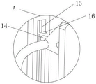
FIG. 2 is an enlarged view of FIG. 1 at A;
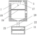
FIG. 3 is the schematic diagram of the internal structure of the purification box of the flue gas purification treatment device for chemical plastic production provided by the utility model.
Illustration of the drawings:
1. a carrier plate; 2. an adjusting bracket; 3. an air intake cover; 4. a servo motor; 5. a purification box; 6. an exhaust pipe; 7. a water inlet pipe; 8. a water pump; 9. a circulation pipe; 10. a push rod; 11. a filter box; 12. a hose; 13. a universal wheel; 14. a resistance shaft; 15. a screw rod; 16. a slider; 17. a fan; 18. a spherical nozzle; 19. a first filter screen; 20. a water outlet pipe; 21. a valve; 22. and a second filter screen.
Detailed Description
The technical solutions in the embodiments of the present invention will be described clearly and completely with reference to the accompanying drawings in the embodiments of the present invention, and it is obvious that the described embodiments are only some embodiments of the present invention, not all embodiments. Based on the embodiments in the present invention, all other embodiments obtained by a person skilled in the art without creative work belong to the protection scope of the present invention.
In the description of the present invention, it should be noted that the terms "center", "upper", "lower", "left", "right", "vertical", "horizontal", "inner", "outer", and the like indicate orientations or positional relationships based on the orientations or positional relationships shown in the drawings, and are only for convenience of description and simplification of description, but do not indicate or imply that the device or element referred to must have a specific orientation, be constructed and operated in a specific orientation, and thus, should not be construed as limiting the present invention; the terms "first," "second," and "third" are used for descriptive purposes only and are not to be construed as indicating or implying relative importance, and furthermore, unless otherwise explicitly stated or limited, the terms "mounted," "connected," and "connected" are to be construed broadly and may be, for example, fixedly connected, detachably connected, or integrally connected; can be mechanically or electrically connected; they may be connected directly or indirectly through intervening media, or they may be interconnected between two elements. The specific meaning of the above terms in the present invention can be understood in specific cases to those skilled in the art.
Referring to fig. 1-3, the present invention provides an embodiment: a flue gas purification treatment device for chemical engineering plastic production comprises a bearing plate 1, an adjusting frame 2 is fixedly connected to the right side of the top end of the bearing plate 1, sliders 16 are connected to the inner walls of the front end and the rear end of the adjusting frame 2 in a sliding manner, a resistance shaft 14 is connected to one end of the inner side of each slider 16 in a rotating manner, one end of the inner side of each resistance shaft 14 is respectively and fixedly connected to two sides of an air suction cover 3, a servo motor 4 is fixedly connected to the rear of the top end of the adjusting frame 2, a lead screw 15 is fixedly connected to the driving end of the servo motor 4, a purification box 5 is fixedly connected to the left side of the bearing plate 1 corresponding to the adjusting frame 2, a first filter screen 19 is fixedly connected to the middle of the inner wall of the purification box 5, a water outlet pipe 20 is fixedly connected to the middle of the bottom end of the purification box 5, a filter box 11 is fixedly connected to the bottom of the left end of the filter box 11, a circulating pipe 9 is fixedly connected to the top end of the circulating pipe 8, water pump 8's top fixedly connected with inlet tube 7, form the negative pressure through 17 work messenger's purge tank 5 of fan, the flue gas is inhaled in purge tank 5 through breathing in cover 3 and hose 12, can filter the back through blast pipe 6 discharges with the harmful dust in the flue gas through first filter screen 19, through the water in the water pump 8 extraction rose box 11 and by the blowout of spherical shower nozzle 18, can wash first filter screen 19, make first filter screen 19 surface adsorption's smoke and dust drop.
The universal wheels 13 are fixedly connected at four corners of the bottom end of the bearing plate 1, the push rod 10 is fixedly connected at the left side of the top end of the bearing plate 1, the movement of the whole device is facilitated, the flexibility is improved, the hose 12 is fixedly connected at the left end of the air suction cover 3, the left end of the hose 12 is fixedly connected at the bottom of the right end of the purification box 5, the outer diameter of the screw rod 15 is in threaded connection with the inner wall of the rear sliding block 16, the bottom end of the screw rod 15 is rotatably connected with the inner wall of the bottom end of the adjusting frame 2, the valve 21 is arranged in front of the water outlet pipe 20, the middle part of the inner wall of the filter box 11 is fixedly connected with the second filter screen 22, the valve 21 is opened, sewage is discharged into the filter box 11 and can be recycled after being filtered by the second filter screen 22, the pipe body of the water inlet pipe 7 penetrates through the top of the left end of the purification box 5, the spherical spray head 18 is arranged at the tail end of the water inlet pipe 7, the cleaning area is improved by the spherical spray head 18, the fan 17 is fixedly connected at the inner wall of the right side of the top end of the purification box 5, an exhaust pipe 6 is fixedly connected to the right side of the top end of the purification box 5.
The working principle is as follows: firstly, the valve 21 is closed, the fan 17 works to form negative pressure in the purifying box 5, the smoke is sucked into the purifying box 5 through the air suction cover 3 and the hose 12, harmful dust in the smoke can be filtered through the first filter screen 19 and then discharged through the exhaust pipe 6, water in the filter box 11 is pumped through the water pump 8 and sprayed out through the spherical spray head 18, the first filter screen 19 can be washed, smoke adsorbed on the surface of the first filter screen 19 falls off, the filtering effect of the first filter screen 19 is ensured, finally, the valve 21 is opened, sewage is discharged into the filter box 11 and can be recycled after being filtered through the second filter screen 22, the harm of the smoke to human bodies and the environment is prevented, meanwhile, the filter device is convenient to clean, the working efficiency is improved, the lead screw 15 is driven to rotate through the servo motor 4, the slide block 16 is driven to slide in the adjusting frame 2 through the lead screw 15, and therefore, the height adjustment of the air suction cover 3 can be realized, the angle of the air suction cover 3 can be adjusted by rotating the resistance shaft 14, so that the position of the air suction cover 3 is flexible and changeable, the position for generating smoke can be better aligned, and the smoke absorption effect is improved.
Finally, it should be noted that: although the present invention has been described in detail with reference to the foregoing embodiments, it will be apparent to those skilled in the art that modifications and variations can be made in the embodiments or in part of the technical features of the embodiments without departing from the spirit and the scope of the invention.
Claims (8)
1. The utility model provides a gas cleaning processing apparatus for chemical industry plastics production, includes loading board (1), its characterized in that: the air purifier is characterized in that an adjusting frame (2) is fixedly connected to the right side of the top end of the bearing plate (1), sliders (16) are slidably connected to inner walls of the front end and the rear end of the adjusting frame (2), resistance shafts (14) are rotatably connected to one ends of the inner sides of the sliders (16), one ends of the inner sides of the resistance shafts (14) are fixedly connected to two sides of the air suction cover (3), a servo motor (4) is fixedly connected to the rear of the top end of the adjusting frame (2), a lead screw (15) is fixedly connected to a driving end of the servo motor (4), a purifying box (5) is fixedly connected to the left side, corresponding to the adjusting frame (2), of the top end of the bearing plate (1), a first filter screen (19) is fixedly connected to the middle of the inner wall of the purifying box (5), a water outlet pipe (20) is fixedly connected to the middle of the bottom end of the purifying box (5), and a filter box (11) is fixedly connected to the bottom end of the water outlet pipe (20), the water pump is characterized in that a circulating pipe (9) is fixedly connected to the bottom of the left end of the filter box (11), a water pump (8) is fixedly connected to the top end of the circulating pipe (9), and a water inlet pipe (7) is fixedly connected to the top end of the water pump (8).
2. The flue gas purification treatment device for chemical engineering plastic production according to claim 1, characterized in that: the bottom four corners department of loading board (1) all fixedly connected with universal wheel (13), the top left side fixedly connected with push rod (10) of loading board (1).
3. The flue gas purification treatment device for chemical engineering plastic production according to claim 1, characterized in that: the left end fixedly connected with hose (12) of cover (3) of breathing in, the left end fixed connection of hose (12) is in the right-hand member bottom of purifying box (5).
4. The flue gas purification treatment device for chemical engineering plastic production according to claim 1, characterized in that: the outer diameter of the screw rod (15) is in threaded connection with the inner wall of the rear sliding block (16), and the bottom end of the screw rod (15) is rotatably connected with the inner wall of the bottom end of the adjusting frame (2).
5. The flue gas purification treatment device for chemical engineering plastic production according to claim 1, characterized in that: a valve (21) is arranged in front of the water outlet pipe (20), and a second filter screen (22) is fixedly connected to the middle part of the inner wall of the filter box (11).
6. The flue gas purification treatment device for chemical engineering plastic production according to claim 1, characterized in that: the body of inlet tube (7) runs through the left end top of purifying box (5), the end of inlet tube (7) is provided with spherical shower nozzle (18).
7. The flue gas purification treatment device for chemical engineering plastic production according to claim 1, characterized in that: the inner wall of the right side of the top end of the purification box (5) is fixedly connected with a fan (17).
8. The flue gas purification treatment device for chemical engineering plastic production according to claim 1, characterized in that: the right side of the top end of the purification box (5) is fixedly connected with an exhaust pipe (6).
Priority Applications (1)
| Application Number | Priority Date | Filing Date | Title |
|---|---|---|---|
| CN202220829809.5U CN216457606U (en) | 2022-04-12 | 2022-04-12 | A gas cleaning processing apparatus for chemical industry plastics production |
Applications Claiming Priority (1)
| Application Number | Priority Date | Filing Date | Title |
|---|---|---|---|
| CN202220829809.5U CN216457606U (en) | 2022-04-12 | 2022-04-12 | A gas cleaning processing apparatus for chemical industry plastics production |
Publications (1)
| Publication Number | Publication Date |
|---|---|
| CN216457606U true CN216457606U (en) | 2022-05-10 |
Family
ID=81435192
Family Applications (1)
| Application Number | Title | Priority Date | Filing Date |
|---|---|---|---|
| CN202220829809.5U Active CN216457606U (en) | 2022-04-12 | 2022-04-12 | A gas cleaning processing apparatus for chemical industry plastics production |
Country Status (1)
| Country | Link |
|---|---|
| CN (1) | CN216457606U (en) |
-
2022
- 2022-04-12 CN CN202220829809.5U patent/CN216457606U/en active Active
Similar Documents
| Publication | Publication Date | Title |
|---|---|---|
| CN210699353U (en) | Dust-free workshop air purification device | |
| CN210568937U (en) | Indoor air purification treatment device | |
| CN111249821A (en) | Industrial waste gas treatment device | |
| CN207856619U (en) | A kind of gas cleaning plant of activated carbon adsorption | |
| CN216457606U (en) | A gas cleaning processing apparatus for chemical industry plastics production | |
| CN111237899A (en) | Air purification equipment for green building and use method | |
| CN213590072U (en) | Energy-saving and environment-friendly equipment for waste gas treatment | |
| CN212548921U (en) | Dodecyl sodium sulfate tail gas processing apparatus | |
| CN109999593B (en) | Low-cost high-efficiency dust removing device | |
| CN209714716U (en) | A kind of injection molding machine waste gas collection device | |
| CN112934900A (en) | Dust removing device and dust removing method for pharmacy | |
| CN219539849U (en) | Smoke dust treatment system for rubber production | |
| CN111603875A (en) | Waste gas purification treatment device for lost foam casting | |
| CN218980965U (en) | Dust suppression device | |
| CN215692672U (en) | Waste gas treatment and dust removal environmental protection equipment | |
| CN210874630U (en) | Spiral dust treatment device is used in laboratory convenient to wash | |
| CN219272484U (en) | SCR all-in-one of continuous desulfurization dust removal denitration | |
| CN219744349U (en) | Environment-friendly smoke and dust clarifier | |
| CN212841908U (en) | Air conditioner with air filter | |
| CN217662369U (en) | Indoor air filter for purification engineering | |
| CN220546728U (en) | Acid-base waste gas treatment equipment capable of realizing waste layering | |
| CN213528066U (en) | Dust-removing desulfurizing purifier | |
| CN216738137U (en) | Dynamic desulfurization and regeneration device for waste rubber | |
| CN214701165U (en) | Integrated urban multidimensional intelligent haze removal equipment | |
| CN214389459U (en) | Gas purification and recovery equipment |
Legal Events
| Date | Code | Title | Description |
|---|---|---|---|
| GR01 | Patent grant | ||
| GR01 | Patent grant |