CN216371165U - Fixed mechanical fixture for machining - Google Patents
Fixed mechanical fixture for machining Download PDFInfo
- Publication number
- CN216371165U CN216371165U CN202122872380.6U CN202122872380U CN216371165U CN 216371165 U CN216371165 U CN 216371165U CN 202122872380 U CN202122872380 U CN 202122872380U CN 216371165 U CN216371165 U CN 216371165U
- Authority
- CN
- China
- Prior art keywords
- plate
- fixed
- workbench
- limiting plate
- sliding block
- Prior art date
- Legal status (The legal status is an assumption and is not a legal conclusion. Google has not performed a legal analysis and makes no representation as to the accuracy of the status listed.)
- Active
Links
Images


Abstract
The utility model discloses a fixed mechanical fixture for machining, which comprises a workbench, wherein a placing box is arranged at the lower end of the workbench, 2 fixed cover plates are symmetrically arranged at the lower end of the placing box, and a supporting base is symmetrically arranged at the lower end of the placing box, and the fixed mechanical fixture also comprises: 2 partition plates which are arranged in total and are arranged inside the placing box; and the bearing sliding block is arranged in a T shape and is in sliding connection with the workbench through a groove formed in the workbench. This fixed machinery anchor clamps for machining sets up first limiting plate and second limiting plate into detachable construction, can fix not unidimensional work piece, realizes processing the work piece, can realize placing device and equipment through the division board, and changes the position of accepting the slider through rotating the screw rod, alright fix the position of fixed plate this moment, can realize carrying out regulation on a large scale to the position of first limiting plate and second limiting plate, increase the application range of device.
Description
Technical Field
The utility model relates to the technical field of machining, in particular to a fixed mechanical clamp for machining.
Background
The machining is to machine the workpiece through mechanical equipment, so that the appearance and the size of the workpiece are changed, and therefore, in the process of machining the workpiece, the workpiece needs to be clamped and fixed, so that the workpiece is conveniently machined.
The publication number is: CN213080755U, which comprises an installation seat, wherein fixing bolts are installed between the peripheral edges of the upper and lower surfaces of the installation seat in a threaded manner, a weight block is arranged at the middle position of the upper surface of the installation seat, a welding plate is vertically and fixedly installed at the bottom position of the outer surface of the weight block, a bearing column is vertically arranged at the middle position of the upper surface of the weight block, a clamping seat is welded at the upper end of the bearing column, inner threaded sleeves are fixedly installed at the middle positions of the two side walls of the clamping seat, the guide column positioned and installed by the inner threaded sleeves is horizontally adjusted under the action of threaded assembly, and a piston block guided and installed by the positioning sleeves is used as a connector to realize flexible assembly between the guide column and a vertical plate, so that horizontal thrust can be applied to the clamp body when the horizontal position of the guide column is adjusted, and the horizontal movement of the clamp body is realized to improve the flexibility of clamping use, the sliding table installed in the cavity in a limiting mode serves as a supporting body to provide installation support of the guide pillar, so that when the clamp structure is pushed, the sliding table can rotate in the cavity to adjust the fixed angle of the clamp structure, the adjusting structure is reinforced by the pressing sleeve installed in a guide groove in a locating mode, and the stability of the fixed angle adjusting operation of the clamp structure is improved.
However, there are some problems in the use process of the device, for example, the device needs to be manually rotated in the process of clamping the workpiece, which is time-consuming and labor-consuming, and the device is difficult to clamp and fix round and arc workpieces by adopting a plate-shaped structure, so that the workpieces are easy to move in the processing process.
SUMMERY OF THE UTILITY MODEL
The utility model aims to provide a fixed mechanical clamp for machining, which aims to solve the problems that in the background art, workpieces need to be manually rotated in the clamping process, and the workpieces are easy to move when clamped and machined by adopting a plate-shaped structure.
In order to achieve the purpose, the utility model provides the following technical scheme: a fixed mechanical fixture for machining comprises a workbench, a placing box is installed at the lower end of the workbench, 2 fixed cover plates are symmetrically arranged at the lower end of the placing box, and a supporting base is symmetrically arranged at the lower end of the placing box
Further comprising:
2 partition plates which are arranged in total and are arranged inside the placing box;
the bearing sliding block is arranged in a T shape, is in sliding connection with the workbench through a groove formed in the workbench, and the outer surface of the bearing sliding block is smooth;
the fixed plate is arranged at the upper end of the bearing slide block and is of a square plate-shaped structure;
the electric telescopic rod is arranged at the upper end of the fixed plate and is connected with the movable plate;
and the mounting screws are mutually connected with the movable plate through threaded holes formed in the movable plate, penetrate through the connecting plate and are mutually connected with the movable plate.
Preferably, the receiving slide block is connected with the rotating screw rod through a threaded hole formed in the upper end of the receiving slide block, the rotating screw rod and the workbench form a rotating mechanism through a bearing installed on the workbench, the rotating screw rod is connected with the rotating handle, and the rotating screw rod is driven to rotate through the rotating handle.
Preferably, the rotating handle is attached to the positioning rod through a groove formed in the upper end of the rotating handle, a movable sliding block is mounted at the lower end of the positioning rod and is in sliding connection with the workbench, and the outer surface of the movable sliding block is smooth.
Preferably, a pulling plate is installed at the upper end of the positioning rod, a limiting spring is installed on the positioning rod, the limiting spring is connected with the workbench, and the positioning rod is conveniently pulled through the limiting spring through the structure.
Preferably, the moving plate is symmetrically provided with driving rods, the driving rods are symmetrically provided with connecting sliding blocks, the connecting sliding blocks are in sliding connection with the fixed sleeve through grooves formed in the fixed sleeve, meanwhile, the fixed sleeve is arranged on the fixed plate, and the moving range of the driving rods is conveniently limited through the connecting sliding blocks.
Preferably, install first limiting plate on the connecting plate, just first limiting plate and second limiting plate interconnect, and the second limiting plate sets up to soft rubber material, simultaneously first limiting plate with the second limiting plate all sets up to arc platelike structure, and through above-mentioned structure, it is fixed to be convenient for carry out the centre gripping through first limiting plate and second limiting plate to the work piece.
Compared with the prior art, the utility model has the beneficial effects that:
(1) the fixed mechanical clamp for machining is provided with the first limiting plate and the second limiting plate, and the first limiting plate and the second limiting plate are arranged to be detachable structures, so that the arc degree of the clamping device can be changed conveniently, the fixed mechanical clamp can be adapted to stable clamping of workpieces with different shapes conveniently, workpieces with different sizes can be fixed, the workpieces can be machined, and the situation that the workpieces move in the machining process is avoided;
(2) this fixed machinery anchor clamps for machining is provided with and rotates the screw rod, accepts slider, locating lever and division board, can realize placing device and equipment this moment through the division board, and changes the position of accepting the slider through rotating the screw rod, alright fix the position of fixed plate this moment, can realize carrying out regulation on a large scale to the position of first limiting plate and second limiting plate, increase the application range of device.
Drawings
FIG. 1 is a schematic front view of a fixed cover plate according to the present invention;
FIG. 2 is a schematic cross-sectional front view of the worktable according to the present invention;
FIG. 3 is a schematic top view of a cross-sectional view of a first limiting plate of the present invention;
FIG. 4 is a schematic front sectional view of the twist grip of the present invention;
FIG. 5 is a schematic side view of a cross-sectional structure of a positioning rod of the present invention;
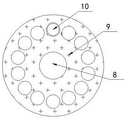
fig. 6 is a schematic perspective view of a second limiting plate according to the present invention.
In the figure: 1. a work table; 2. placing a box; 3. fixing the cover plate; 4. a support base; 5. a partition plate; 6. carrying the sliding block; 7. a fixing plate; 8. rotating the screw; 9. rotating the handle; 10. positioning a rod; 11. moving the slide block; 12. pulling the movable plate; 13. a limiting spring; 14. an electric telescopic rod; 15. moving the plate; 16. driving the rod; 17. connecting the sliding block; 18. fixing the sleeve; 19. mounting screws; 20. a connecting plate; 21. a first limit plate; 22. and a second limiting plate.
Detailed Description
The technical solutions in the embodiments of the present invention will be clearly and completely described below with reference to the drawings in the embodiments of the present invention, and it is obvious that the described embodiments are only a part of the embodiments of the present invention, and not all of the embodiments. All other embodiments, which can be derived by a person skilled in the art from the embodiments given herein without making any creative effort, shall fall within the protection scope of the present invention.
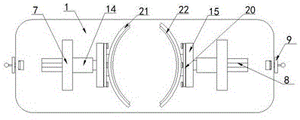
Referring to fig. 1-6, the present invention provides a technical solution: a fixed mechanical fixture for machining comprises a workbench 1, a placing box 2 is installed at the lower end of the workbench, 2 lower ends of the placing box are symmetrically provided with 2 fixed cover plates 3, and the lower ends of the placing box 2 are symmetrically provided with a supporting base 4
Further comprising:
2 partition plates 5 which are arranged in total and are installed inside the placing box 2;
the bearing sliding block 6 is arranged in a T shape, is in sliding connection with the workbench 1 through a groove formed in the workbench 1, and the outer surface of the bearing sliding block 6 is smooth;
the fixed plate 7 is arranged at the upper end of the bearing slide block 6, and the fixed plate 7 is of a square plate-shaped structure;
the electric telescopic rod 14 is arranged at the upper end of the fixed plate 7, and the electric telescopic rod 14 is connected with the movable plate 15;
the mounting screw 19 is connected with the moving plate 15 through a threaded hole formed in the moving plate 15, the mounting screw 19 penetrates through the connecting plate 20, and the connecting plate 20 is connected with the moving plate 15;
in this example, the receiving slide block 6 is connected with the rotating screw 8 through a threaded hole formed in the upper end of the receiving slide block, the rotating screw 8 forms a rotating mechanism with the workbench 1 through a bearing arranged on the workbench 1, and the rotating screw 8 is connected with the rotating handle 9; the rotary handle 9 is mutually attached to the positioning rod 10 through a groove formed in the upper end of the rotary handle, the lower end of the positioning rod 10 is provided with a movable sliding block 11, the movable sliding block 11 is in sliding connection with the workbench 1, and the outer surface of the movable sliding block 11 is smooth; a pulling plate 12 is arranged at the upper end of the positioning rod 10, a limiting spring 13 is arranged on the positioning rod 10, and the limiting spring 13 is connected with the workbench 1;
when the position of the fixed plate 7 needs to be changed, the pulling plate 12 in fig. 4 is pulled, because the pulling plate 12 is connected with the positioning rod 10, the positioning rod 10 starts to move, namely the limiting spring 13 starts to be compressed and deformed, at this time, the positioning rod 10 is not attached to the groove formed on the rotating handle 9 any more, so that the rotating handle 9 can rotate, because the rotating handle 9 is provided with the rotating screw 8, the rotating screw 8 starts to rotate, namely the rotating screw 8 in fig. 1 drives the bearing slide block 6 arranged at the upper end thereof to move left and right, namely the fixed plate 7 arranged on the bearing slide block 6 starts to move, so that workpieces with different sizes can be clamped and fixed, the lower end of the workbench 1 is provided with the placing box 2, the partition plate 5 is arranged in the placing box 2, and the device and the workpieces can be placed through the partition plate 5, the condition of loss is avoided;
the moving plate 15 is symmetrically provided with driving rods 16, the driving rods 16 are symmetrically provided with connecting sliding blocks 17, the connecting sliding blocks 17 are in sliding connection with the fixed sleeve 18 through grooves formed in the fixed sleeve 18, and the fixed sleeve 18 is arranged on the fixed plate 7; a first limiting plate 21 is mounted on the connecting plate 20, the first limiting plate 21 and the second limiting plate 22 are connected with each other, the second limiting plate 22 is made of soft rubber, and the first limiting plate 21 and the second limiting plate 22 are both of arc-shaped plate structures;
when the work piece is required to be clamped, the work piece is placed between the second limiting plates 22, then the electric telescopic rod 14 starts to work, because the movable plate 15 is installed on the electric telescopic rod 14, and the movable plate 15 is connected with the connecting plates 20 through the installation screws 19, so that the first limiting plate 21 and the second limiting plate 22 which are arranged at the upper end of the connecting plates 20 are driven to move, namely the first limiting plate 21 and the second limiting plate 22 start to move towards the direction close to the work piece, so that the work piece is clamped and fixed through the first limiting plate 21 and the second limiting plate 22, in the moving process of the first limiting plate 21 and the second limiting plate 22, the moving direction of the work piece 15 is changed through the driving rod 16, the connecting slide block 17 and the fixed sleeve 18, and the moving range of the movable plate 15 is limited.
The working principle is as follows: when needs use this device, rotation through rotating screw rod 8, can realize changing the position of accepting slider 6, just drive the fixed plate 7 of accepting the installation on slider 6 this moment promptly and remove, can realize moving the device and the structure that set up on fixed plate 7, thereby can realize carrying out the centre gripping to the great work piece of size difference and fix, and carrying out the in-process of centre gripping to the work piece, drive movable plate 15 through electric telescopic handle 14 and remove, thereby realize driving the removal to first limiting plate 21 and second limiting plate 22, can realize carrying out the centre gripping fixedly to the work piece, thereby be convenient for process the work piece, this is exactly this machining uses fixed mechanical fixture's theory of operation.
Although embodiments of the present invention have been shown and described, it will be appreciated by those skilled in the art that changes, modifications, substitutions and alterations can be made in these embodiments without departing from the principles and spirit of the utility model, the scope of which is defined in the appended claims and their equivalents.
Claims (6)
1. The utility model provides a fixed machinery anchor clamps for machining, includes workstation (1), and the lower extreme is installed and is placed case (2), just it is provided with 2 fixed apron (3) to place case (2) lower extreme symmetry, and it is provided with support base (4) to place case (2) lower extreme symmetry
It is characterized by also comprising:
2 partition plates (5) which are arranged in total and are arranged inside the placing box (2);
the bearing sliding block (6) is arranged in a T shape, is in sliding connection with the workbench (1) through a groove formed in the workbench (1), and the outer surface of the bearing sliding block (6) is smooth;
the fixing plate (7) is installed at the upper end of the bearing sliding block (6), and the fixing plate (7) is of a square plate-shaped structure;
the electric telescopic rod (14) is arranged at the upper end of the fixed plate (7), and the electric telescopic rod (14) is connected with the moving plate (15);
the mounting screw (19) is connected with the moving plate (15) through a threaded hole formed in the moving plate (15), the mounting screw (19) penetrates through the connecting plate (20), and the connecting plate (20) is connected with the moving plate (15).
2. A fixed mechanical jig for machining according to claim 1, characterized in that: the bearing sliding block (6) is connected with the rotating screw rod (8) through a threaded hole formed in the upper end of the bearing sliding block, the rotating screw rod (8) and the workbench (1) form a rotating mechanism through a bearing arranged on the workbench (1), and the rotating screw rod (8) is connected with the rotating handle (9) mutually.
3. A fixed mechanical jig for machining according to claim 2, characterized in that: the rotary handle (9) is attached to the positioning rod (10) through a groove formed in the upper end of the rotary handle, a movable sliding block (11) is installed at the lower end of the positioning rod (10), the movable sliding block (11) is in sliding connection with the workbench (1), and meanwhile the outer surface of the movable sliding block (11) is smooth.
4. A fixed mechanical jig for machining according to claim 3, characterized in that: the upper end of the positioning rod (10) is provided with a pulling plate (12), the positioning rod (10) is provided with a limiting spring (13), and the limiting spring (13) is connected with the workbench (1).
5. A fixed mechanical jig for machining according to claim 1, characterized in that: the movable plate (15) is symmetrically provided with driving rods (16), the driving rods (16) are symmetrically provided with connecting sliding blocks (17), the connecting sliding blocks (17) are in sliding connection with the fixed sleeve (18) through grooves formed in the fixed sleeve (18), and meanwhile the fixed sleeve (18) is installed on the fixed plate (7).
6. A fixed mechanical jig for machining according to claim 1, characterized in that: install first limiting plate (21) on connecting plate (20), just first limiting plate (21) and second limiting plate (22) interconnect, and second limiting plate (22) set up to soft rubber material, simultaneously first limiting plate (21) with second limiting plate (22) all set up to arc platelike structure.
Priority Applications (1)
| Application Number | Priority Date | Filing Date | Title |
|---|---|---|---|
| CN202122872380.6U CN216371165U (en) | 2021-11-23 | 2021-11-23 | Fixed mechanical fixture for machining |
Applications Claiming Priority (1)
| Application Number | Priority Date | Filing Date | Title |
|---|---|---|---|
| CN202122872380.6U CN216371165U (en) | 2021-11-23 | 2021-11-23 | Fixed mechanical fixture for machining |
Publications (1)
| Publication Number | Publication Date |
|---|---|
| CN216371165U true CN216371165U (en) | 2022-04-26 |
Family
ID=81217204
Family Applications (1)
| Application Number | Title | Priority Date | Filing Date |
|---|---|---|---|
| CN202122872380.6U Active CN216371165U (en) | 2021-11-23 | 2021-11-23 | Fixed mechanical fixture for machining |
Country Status (1)
| Country | Link |
|---|---|
| CN (1) | CN216371165U (en) |
-
2021
- 2021-11-23 CN CN202122872380.6U patent/CN216371165U/en active Active
Similar Documents
| Publication | Publication Date | Title |
|---|---|---|
| CN111872717A (en) | Anchor clamps for numerical control machining | |
| CN213827529U (en) | Laser marking machine with regulatory function | |
| CN216371165U (en) | Fixed mechanical fixture for machining | |
| CN210059870U (en) | Drilling device for drilling two ends of rotor shaft | |
| CN214518862U (en) | Generator end cover machining tool based on five-axis machining center | |
| CN113799013B (en) | Anchor clamps for mechanical maintenance | |
| CN213137025U (en) | Punching device for plate processing based on electronic information technology | |
| CN215036824U (en) | Rapid clamp for metal fitting machining | |
| CN215393902U (en) | Four-axis anchor clamps of convenient debugging | |
| CN218363485U (en) | Fastening clamp convenient to adjust for machine manufacturing | |
| CN217513230U (en) | Fixture for welding electromechanical equipment parts | |
| CN220660528U (en) | High-performance photovoltaic profile machining tool | |
| CN219025430U (en) | Auxiliary feeding device of drawing machine | |
| CN218802138U (en) | Positioning device with clamping structure | |
| CN219852368U (en) | Cutting device is used in processing of water conservancy pipeline that centre gripping is stable | |
| CN215432585U (en) | Stepped drill production and processing clamp | |
| CN219114193U (en) | Acrylic plate supporting device for table saw | |
| CN220218078U (en) | Positioning device | |
| CN219404080U (en) | Clamp tool for coupler assembly processing | |
| CN220806001U (en) | Adjustable clamp | |
| CN220739107U (en) | High-efficient feeding bending mechanism | |
| CN210649649U (en) | Anchor clamps are used in machine parts production and processing | |
| CN220094240U (en) | Positioning device for bearing ring machining | |
| CN220372276U (en) | Abrasive belt bracket machining tool of abrasive belt sand disc machine | |
| CN220612394U (en) | Tooling for machining inclined holes in box body of wind power generator |
Legal Events
| Date | Code | Title | Description |
|---|---|---|---|
| GR01 | Patent grant | ||
| GR01 | Patent grant |