CN216348994U - Be applicable to water level detection device for hydraulic engineering - Google Patents
Be applicable to water level detection device for hydraulic engineering Download PDFInfo
- Publication number
- CN216348994U CN216348994U CN202122775155.0U CN202122775155U CN216348994U CN 216348994 U CN216348994 U CN 216348994U CN 202122775155 U CN202122775155 U CN 202122775155U CN 216348994 U CN216348994 U CN 216348994U
- Authority
- CN
- China
- Prior art keywords
- wall
- water level
- monitoring
- detection device
- level detection
- Prior art date
- Legal status (The legal status is an assumption and is not a legal conclusion. Google has not performed a legal analysis and makes no representation as to the accuracy of the status listed.)
- Active
Links
Images


Landscapes
- Level Indicators Using A Float (AREA)
Abstract
The utility model relates to the technical field of hydraulic engineering and discloses a water level detection device suitable for hydraulic engineering, which comprises a monitoring cylinder body, wherein the monitoring cylinder body is fixedly installed on a dam, the outer wall of the monitoring cylinder body is provided with a rectangular groove, a warning device is arranged above the monitoring cylinder body, a water level detection device is arranged above the warning device, a monitoring room is arranged on the dam, the water level detection device comprises a belt, a belt pulley, a first rotating shaft, a rotating disc, a rope and a scale, a first bearing is arranged above the outer wall of the monitoring room, the first rotating shaft sequentially penetrates through the inner wall of the first bearing and the monitoring room from outside to inside and extends in a box, and the belt pulley is fixedly sleeved on the outer wall of the first rotating shaft and is positioned outside the monitoring room. The utility model can directly observe the scales indoors for reading, improves the accuracy and the efficiency of measurement and can warn the water level.
Description
Technical Field
The utility model relates to the technical field of hydraulic engineering, in particular to a water level detection device suitable for hydraulic engineering.
Background
The hydraulic engineering mainly learns basic theories and basic knowledge in the aspects of mathematics, mechanics, building structures and the like necessary for hydraulic and hydroelectric engineering construction, so that students obtain necessary basic training of engineering design methods, construction management methods and scientific research methods, and have basic capabilities in the aspects of hydraulic and hydroelectric engineering surveying, planning, designing, constructing, scientific research, management and the like.
In hydraulic engineering, need to detect the water level, according to chinese patent "a be applicable to water level detection device for hydraulic engineering", and the publication number is: "CN 213748670U", this patent is used through the cooperation that sets up measurement sighting rod, spout, slider, buoy, scale mark, first scale mark, second scale mark, third scale mark and fourth scale mark, has solved current water level detection device for hydraulic engineering and has observed the scale comparatively inconvenient, and scale mark numerical dimension is less, even also need closely observe comparatively inconvenient problem daytime. However, the observation is facilitated mainly through the buoy and the large scale, the inconvenience in observation is solved, and the observation is carried out outdoors at night, so that the efficiency is affected.
SUMMERY OF THE UTILITY MODEL
The utility model aims to provide a water level detection device suitable for hydraulic engineering, which can achieve the purposes of directly observing scales indoors for reading, improving the accuracy and the efficiency of measurement and warning the water level.
In order to achieve the purpose, the utility model provides the following technical scheme: the utility model provides a be applicable to water level detection device for hydraulic engineering, includes the monitoring cylinder body, monitoring cylinder body fixed mounting is on the dam, the rectangular channel has been seted up to the outer wall of monitoring cylinder body, the top of monitoring cylinder body is provided with warning device, warning device's top is provided with water level detection device, be provided with the monitoring room on the dam, water level detection device includes the belt, the belt pulley, first pivot, the carousel, the rope, the scale, the outer wall top in monitoring room is provided with first bearing, first pivot is run through by outer and interior in proper order the inner wall of first bearing and monitoring room and incasement extend, the fixed outer wall of establishing at first pivot of belt pulley is located the outside in monitoring room.
Preferably, the turntable is fixedly sleeved on the outer wall of the extending end of the first rotating shaft, one end of the rope winds on the turntable, a heavy hammer indicator needle is arranged at one end, far away from the turntable, of the rope, and the graduated scale is fixedly installed on the inner wall of the monitoring room. The scale can accurately read the reading.
Preferably, the warning device includes the floating block, the toothed plate, the spur gear, the kicking block, the fixed plate, the warning bell, the toothed plate runs through the monitoring cylinder body and downwardly extending from top to bottom, floating block fixed mounting is in the extension end of toothed plate, the inner wall of monitoring cylinder body is seted up flutedly, be provided with the stopper in the recess, the one end fixed connection that the recess was kept away from to the stopper is at the back of toothed plate. The gear plate can be fixed through the arranged limiting blocks and the grooves.
Preferably, the outer wall below in monitoring room is provided with the second bearing, the second pivot is pegged graft the inner wall of first bearing rotates with the monitoring room to be connected, the quantity of belt pulley is two, another the outer wall at the second pivot is established in proper order to belt pulley and spur gear cover, belt transmission connects on two belt pulleys, fixed plate fixed mounting is located the top of first bearing at the outer wall in monitoring room, the warning bell hangs in the bottom of fixed plate, kicking block fixed connection keeps away from the one end of floating block at the gear board. The warning bell can play a warning role.
The utility model provides a water level detection device suitable for hydraulic engineering. The method has the following beneficial effects:
(1) through the water level detection device, the water level height can be read indoors by directly pointing the heavy hammer pointer to the graduated scale without outdoor observation, and meanwhile, the condition of misreading in remote observation is avoided.
(2) The warning device can impact the warning bell above when the water level reaches the warning height so as to achieve the warning effect and avoid the influence of neglecting the water level on dangerous situations.
Drawings
FIG. 1 is a front view of the present invention;
FIG. 2 is a side view of the present invention;
fig. 3 is a top view of the exterior of the monitoring room of the present invention.
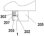
In the figure: 1. monitoring the cylinder body; 2. a warning device; 201. floating blocks; 202. a gear plate; 203. a spur gear; 204. a top block; 205. a fixing plate; 206. a warning bell; 207. a second rotating shaft; 3. a water level detection device; 301. a belt; 302. a belt pulley; 303. a first rotating shaft; 304. a turntable; 305. a rope; 306. a graduated scale; 4. and (5) monitoring the house.
Detailed Description
The technical solutions in the embodiments of the present invention will be clearly and completely described below with reference to the drawings in the embodiments of the present invention, and it is obvious that the described embodiments are only a part of the embodiments of the present invention, and not all of the embodiments. All other embodiments, which can be derived by a person skilled in the art from the embodiments given herein without making any creative effort, shall fall within the protection scope of the present invention.
As shown in fig. 1-3, the present invention provides a technical solution: a water level detection device suitable for hydraulic engineering comprises a monitoring cylinder body 1, wherein the monitoring cylinder body 1 is fixedly installed on a dam, the outer wall of the monitoring cylinder body 1 is provided with a rectangular groove, a warning device 2 is arranged above the monitoring cylinder body 1, the monitoring cylinder body 1 can hit a warning bell 206 above the monitoring cylinder body through the set warning device 2 when the water level reaches an early warning height so as to achieve the warning effect and avoid neglecting the water level and influence dangerous situations, the warning device 2 comprises a floating block 201, a gear plate 202, a spur gear 203, a top block 204, a fixing plate 205 and the warning bell 206, the gear plate 202 penetrates through the monitoring cylinder body 1 from top to bottom and extends downwards, the floating block 201 is fixedly installed at the extending end of the gear plate 202, the inner wall of the monitoring cylinder body 1 is provided with a groove, a limit block is arranged in the groove, one end of the limit block, which is far away from the groove, is fixedly connected to the back of the gear plate 202, the limit block and the groove can fix the gear plate 202, the lower part of the outer wall of the monitoring room 4 is provided with a second bearing, the second rotating shaft 207 is inserted into the inner wall of the first bearing and is rotatably connected with the monitoring room 4, the number of the belt pulleys 302 is two, the other belt pulley 302 and the spur gear 203 are sequentially sleeved on the outer wall of the second rotating shaft 207, the belt 301 is in transmission connection with the two belt pulleys 302, the fixing plate 205 is fixedly installed on the outer wall of the monitoring room 4 and is positioned above the first bearing, the warning bell 206 is hung at the bottom of the fixing plate 205, the top block 204 is fixedly connected at one end of the gear plate 202 far away from the floating block 201, the warning effect can be achieved through the arranged warning bell 206, the water level detection device 3 is arranged above the warning device 2, through the arranged water level detection device 3, the water level height can be directly pointed to the graduated scale 306 through the heavy hammer indicator needle indoors, the water level height can be read, the outdoor observation is not needed, and the condition of misreading of remote observation is avoided, be provided with monitoring room 4 on the dam, water level detection device 3 includes belt 301, belt pulley 302, first pivot 303, carousel 304, rope 305, scale 306, monitoring room 4's outer wall top is provided with first bearing, first pivot 303 runs through the inner wall of first bearing and monitoring room 4 and incasement in proper order by outer and interior, the fixed cover of belt pulley 302 is established in the outer wall of first pivot 303 and is located monitoring room 4's outside, the fixed outer wall of establishing at the extension end of first pivot 303 of carousel 304, the one end of rope 305 is hoarded and is established on carousel 304, the one end that carousel 304 was kept away from to rope 305 is provided with the weight pointer, scale 306 fixed mounting is at monitoring room 4's inner wall, the reading that can be accurate through the scale 306 that sets up.
When using, through the buoyancy of water, float piece 201, thereby drive gear plate 202 come-up, because spur gear 203 and gear plate 202 mesh, so can drive spur gear 203 rotatory, thereby drive second pivot 207 and rotate, then make the belt pulley 302 of bottom rotate, under the transmission of belt 301, make the belt pulley 302 of top rotate, thereby make first pivot 303 rotatory, rotate carousel 304, thereby make rope 305 twined on carousel 304, thereby change the height of rope 305 bottom weight pointer, read out the reading on the scale 306, simultaneously kicking block 204 can the up-movement, when reaching the early warning value, can strike the warning bell 206 of top, thereby play the effect of warning.
Although embodiments of the present invention have been shown and described, it will be appreciated by those skilled in the art that changes, modifications, substitutions and alterations can be made in these embodiments without departing from the principles and spirit of the utility model, the scope of which is defined in the appended claims and their equivalents.
Claims (4)
1. The utility model provides a be applicable to water level detection device for hydraulic engineering, includes monitoring cylinder body (1), monitoring cylinder body (1) fixed mounting is on the dam, the rectangular channel, its characterized in that have been seted up to the outer wall of monitoring cylinder body (1): the top of monitoring cylinder body (1) is provided with warning device (2), the top of warning device (2) is provided with water level detection device (3), be provided with monitoring room (4) on the dam, water level detection device (3) are including belt (301), belt pulley (302), first pivot (303), carousel (304), rope (305), scale (306), the outer wall top of monitoring room (4) is provided with first bearing, first pivot (303) is run through by outer and interior in proper order the inner wall of first bearing and monitoring room (4) and incasement extend, the outer wall of first pivot (303) is located the outside of monitoring room (4) at belt pulley (302) fixed cover.
2. The water level detection device suitable for hydraulic engineering according to claim 1, characterized in that: the fixed cover of carousel (304) is established the outer wall at the extension end of first pivot (303), the one end of rope (305) is established round on carousel (304), the one end that carousel (304) were kept away from in rope (305) is provided with the weight pointer, scale (306) fixed mounting is at the inner wall of monitoring room (4).
3. The water level detection device suitable for hydraulic engineering according to claim 2, characterized in that: warning device (2) are including floating block (201), gear plate (202), spur gear (203), kicking block (204), fixed plate (205), warning bell (206), gear plate (202) from top to bottom runs through monitoring cylinder body (1) and downwardly extending, floating block (201) fixed mounting is held at the extension of gear plate (202), the inner wall of monitoring cylinder body (1) is seted up flutedly, be provided with the stopper in the recess, the back at gear plate (202) is kept away from the one end fixed connection of recess to the stopper.
4. The water level detection device suitable for hydraulic engineering according to claim 3, characterized in that: the outer wall below of monitoring room (4) is provided with the second bearing, and second pivot (207) are pegged graft the inner wall of first bearing rotates with monitoring room (4) to be connected, the quantity of belt pulley (302) is two, another belt pulley (302) and spur gear (203) are established the outer wall at second pivot (207) in proper order, belt (301) transmission is connected on two belt pulleys (302), fixed plate (205) fixed mounting is located the top of first bearing at the outer wall in monitoring room (4), warning bell (206) hangs the bottom at fixed plate (205), kicking block (204) fixed connection is in the one end that floating block (201) were kept away from in gear plate (202).
Priority Applications (1)
| Application Number | Priority Date | Filing Date | Title |
|---|---|---|---|
| CN202122775155.0U CN216348994U (en) | 2021-11-13 | 2021-11-13 | Be applicable to water level detection device for hydraulic engineering |
Applications Claiming Priority (1)
| Application Number | Priority Date | Filing Date | Title |
|---|---|---|---|
| CN202122775155.0U CN216348994U (en) | 2021-11-13 | 2021-11-13 | Be applicable to water level detection device for hydraulic engineering |
Publications (1)
| Publication Number | Publication Date |
|---|---|
| CN216348994U true CN216348994U (en) | 2022-04-19 |
Family
ID=81148060
Family Applications (1)
| Application Number | Title | Priority Date | Filing Date |
|---|---|---|---|
| CN202122775155.0U Active CN216348994U (en) | 2021-11-13 | 2021-11-13 | Be applicable to water level detection device for hydraulic engineering |
Country Status (1)
| Country | Link |
|---|---|
| CN (1) | CN216348994U (en) |
-
2021
- 2021-11-13 CN CN202122775155.0U patent/CN216348994U/en active Active
Similar Documents
| Publication | Publication Date | Title |
|---|---|---|
| CN116519066B (en) | Monitoring and measuring device for flow of wetland water channel | |
| CN202793533U (en) | Riverway water gauge | |
| CN216348994U (en) | Be applicable to water level detection device for hydraulic engineering | |
| CN111623853A (en) | Laser measuring device and method for measuring reservoir water level | |
| CN216283789U (en) | Water level monitoring device for hydraulic engineering | |
| CN211318486U (en) | Surface flow velocity and direction observation device | |
| CN208075988U (en) | A kind of explosion-proof type magnetostriction liquidometer can measure multiple liquid levels | |
| CN112762804A (en) | Verticality detection device for multi-environment use of automatic lubricating system of locomotive auxiliary machine | |
| CN216954737U (en) | Portable water level measuring device | |
| CN206990065U (en) | A kind of hydraulic engineering condensate tank of dehumidifier | |
| CN212228171U (en) | Laser measuring device for measuring reservoir water level | |
| CN211954341U (en) | Water conservancy water and electricity water level sighting rod | |
| CN211552822U (en) | Highway engineering measuring device | |
| CN211696601U (en) | Water level gauge for accurately measuring water level | |
| CN211373777U (en) | Depth measuring rod | |
| CN204788585U (en) | Drilling ground water level meter | |
| CN211696490U (en) | Large watershed environment monitoring device | |
| CN205229142U (en) | Structure of turning on one's side is prevented to crab pool quality of water on -line measuring device unsteady spacing | |
| CN210198599U (en) | Temperature chain real-time observation system | |
| CN207688968U (en) | It is a kind of can be with the electric fluviograph of collimation angle error | |
| CN212482640U (en) | Water gauge for hydraulic engineering management | |
| CN213902345U (en) | Hydrology station data monitoring equipment | |
| CN2819240Y (en) | Rainfall measuring device | |
| CN201731921U (en) | Water level self-recording instrument inside piezometer tube of reservoir dam | |
| CN213933590U (en) | Deflection type water quality detection device |
Legal Events
| Date | Code | Title | Description |
|---|---|---|---|
| GR01 | Patent grant | ||
| GR01 | Patent grant |