CN216334891U - Round bar feeding mechanism - Google Patents
Round bar feeding mechanism Download PDFInfo
- Publication number
- CN216334891U CN216334891U CN202122596969.8U CN202122596969U CN216334891U CN 216334891 U CN216334891 U CN 216334891U CN 202122596969 U CN202122596969 U CN 202122596969U CN 216334891 U CN216334891 U CN 216334891U
- Authority
- CN
- China
- Prior art keywords
- round bar
- frame
- feeding mechanism
- lifting
- baffle
- Prior art date
- Legal status (The legal status is an assumption and is not a legal conclusion. Google has not performed a legal analysis and makes no representation as to the accuracy of the status listed.)
- Active
Links
Images


Abstract
The utility model relates to the field of automation equipment, and discloses a round bar feeding mechanism which is characterized by comprising a frame body, wherein a discharging platform and a discharging part are arranged on the frame body, the discharging platform comprises a platform surface, the platform surface is obliquely arranged and comprises an initial end and a tail end, the round bar can roll from the initial end to the tail end through the inclined arrangement of the table top, the baffle is driven by the discharging air cylinder to move up and down, the distance between the baffle and the table top is adjusted, when the round bar enters the discharging table, the stacking condition can be generated, the stacked round bars are prevented from moving by lifting the baffle plate, the round bars are ensured to move towards the multi-station supporting piece one by one, and the pole and the laminating of baffle prevent that the pole from inclining to send out the pole through pushing away the material cylinder, the setting of slide rail and slider makes the removal in-process of removing the frame more stable, prevents to remove the frame and takes place the slope.
Description
Technical Field
The utility model relates to the field of automation equipment, in particular to a round bar feeding mechanism.
Background
Bolts, which are the most commonly used fixing devices, can tightly connect mechanical equipment and are widely applied to various aspects of daily life and industrial processing;
the bolt is before processing, and the masterbatch is the pole form, and the pole is saved and the workbin in, and the pole is processing for one when processing, and operating personnel pours the pole from the workbin, sends into the conveyer belt, misplaces between the pole to stack, need operating personnel to arrange in order, just can get into next process, extravagant man-hour.
SUMMERY OF THE UTILITY MODEL
Aiming at the defects in the prior art, the utility model aims to provide a round bar feeding mechanism which is used for automatically arranging round bars one by one.
In order to achieve the purpose, the utility model provides the following technical scheme: the utility model provides a pole feeding mechanism, includes the support body, be provided with row material platform and row material portion on the support body, it includes the mesa to arrange the material platform, the mesa slope sets up, the mesa includes initial end and tail end, the position height of initial end is greater than the position height of tail end, it follows one by one to arrange the material portion the initial end extremely the tail end removes.
As a further improvement of the present invention, the discharging part includes a fixed frame, a moving motor and a discharging cylinder, a threaded rod is rotatably connected to the fixed frame, the moving motor is fixedly connected to the fixed frame, an output end of the moving motor is in transmission connection with the threaded rod, a moving frame is in threaded connection with the threaded rod, the discharging cylinder is fixedly connected to the moving frame, and a baffle is fixedly connected to an output end of the discharging cylinder, so that the baffle moves in a vertical direction.
As a further improvement of the utility model, the fixed frame is fixedly connected with a slide rail, the slide rail is arranged in parallel with the threaded rod, the movable frame is fixedly connected with a slide block, and the slide block is connected with the slide rail in a sliding manner.
As a further improvement of the utility model, the baffle plate is provided with a through hole, and the threaded rod passes through the through hole.
As a further improvement of the utility model, two slide rails are arranged and are respectively positioned at two sides of the threaded rod in the length direction.
As a further improvement of the utility model, the frame body is further provided with a lifting and feeding part, and the lifting and feeding part is used for feeding the round rods to the next processing procedure.
As a further improvement of the utility model, the lifting and feeding part comprises a lifting frame, a multi-station supporting part and a multi-station lifting part, wherein a lifting cylinder is fixedly connected to the lifting frame, the output end of the lifting cylinder is fixedly connected with the multi-station lifting part so as to enable the multi-station lifting part to move along the vertical direction, the multi-station lifting part and the multi-station supporting part are in one-to-one correspondence, and when the multi-station lifting part moves upwards, the round bar moves from the current station of the multi-station supporting part to the next station.
As a further improvement of the utility model, the lifting frame is fixedly connected with a material pushing frame, the material pushing frame is fixedly connected with a material pushing cylinder, and the lifting frame is provided with an arc-shaped through groove matched with the round rod.
The utility model has the beneficial effects that: according to the utility model, through the inclined arrangement of the table top, the round rods can roll from the initial end to the tail end, the baffle is driven by the discharging cylinder to move up and down, the distance between the baffle and the table top is adjusted, when the round rods enter the discharging table, stacking conditions can occur, the stacked round rods are prevented from moving through the lifting of the baffle, the round rods are ensured to move towards the multi-station support piece one by one, the round rods are attached to the baffle to prevent the round rods from inclining, the round rods are sent out through the discharging cylinder, and the sliding rail and the sliding block are arranged, so that the moving process of the moving frame is more stable, and the moving frame is prevented from inclining.
Drawings
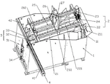
FIG. 1 is a schematic perspective view of the present invention;
FIG. 2 is a schematic perspective view of the present invention taken at an angle toward the discharge cylinder;
FIG. 3 is a schematic view of the internal structure of the elevation feeding part of the present invention.
Reference numerals: 1. a frame body; 11. a discharging platform; 2. a discharge part; 21. a table top; 211. an initial end; 212. a tail end; 22. a fixed mount; 221. a slide rail; 23. a moving motor; 24. a discharge cylinder; 25. a threaded rod; 26. a movable frame; 261. a slider; 27. a baffle plate; 271. a through hole; 3. a lifting and feeding part; 31. a hoisting frame; 32. a multi-station support; 33. a multi-station lifting member; 34. a lift cylinder; 4. a material pushing frame; 41. a material pushing cylinder; 42. an arc-shaped through groove.
Detailed Description
The present invention will be described in further detail with reference to the accompanying drawings and examples. In which like parts are designated by like reference numerals. It should be noted that the terms "front," "back," "left," "right," "upper" and "lower" used in the following description refer to directions in the drawings, and the terms "bottom" and "top," "inner" and "outer" refer to directions toward and away from, respectively, the geometric center of a particular component.
Referring to fig. 1 to 3, the round bar feeding mechanism of the embodiment includes a frame body 1, a discharging table 11 and a discharging portion 2 are disposed on the frame body 1, the discharging table 11 includes a table top 21, the table top 21 is disposed in an inclined manner, an inclination angle of the table top 21 can be set to 5 degrees, the rolling speed of the round bar is controlled, the table top 21 includes an initial end 211 and a final end 212, the height of the initial end 211 is greater than that of the final end 212, the discharging portion 2 enables the round bar to move from the initial end 211 to the final end 212 one by one, an inclined plate is fixedly connected to the initial end 211, one side of the inclined plate away from the initial end 211 inclines upward, the round bar can enter the table top 21 conveniently, the round bar is prevented from sliding off the table top 21, adjusting plates are disposed on two opposite sides of the inclined plate, adjusting holes are disposed on the inclined plate corresponding to the adjusting plates, a distance between the two adjusting plates can be adjusted through the adjusting holes to adapt to round bars with different lengths, the round bar can enter the table-board 21 more conveniently. The discharge part 2 comprises a fixing frame 22, a movable motor 23 and a discharge cylinder 24, a threaded rod 25 is rotatably connected to the fixing frame 22, the movable motor 23 is fixedly connected with the fixing frame 22, the output end of the movable motor 23 is in transmission connection with the threaded rod 25, the threaded rod 25 is provided with a movable frame 26 in threaded connection, the discharge cylinder 24 is fixedly connected to the movable frame 26, a baffle 27 is fixedly connected to the output end of the discharge cylinder 24, so that the baffle 27 moves along the vertical direction, when round bars enter the discharge platform 11, the stacking condition can occur, the lifting through the baffle 27 can prevent the stacked round bars from moving, the round bars are ensured to enter the multi-station support piece 32 in sequence, a lifting feeding part 3 is further arranged on the frame body 1, and the lifting feeding part 3 is used for conveying the round bars to the next processing procedure. The lifting and feeding part 3 comprises a lifting frame 31, a multi-station supporting part 32 and a multi-station lifting part 33, wherein a lifting cylinder 34 is fixedly connected to the lifting frame 31, the output end of the lifting cylinder 34 is fixedly connected with the multi-station lifting part 33, so that the multi-station lifting part 33 moves along the vertical direction, the multi-station lifting part 33 corresponds to the multi-station supporting part 32 one by one, when the multi-station lifting part 33 moves upwards, a round bar moves from the current station of the multi-station supporting part 32 to the next station, five stations are arranged on the multi-station supporting part 32, five stations corresponding to the multi-station supporting part 32 are also arranged on the multi-station lifting part 33, one station is moved upwards by the multi-station lifting part 33, the round bar moves from the current station to the next station on the multi-station supporting part 32, each station on the multi-station supporting part 32 and the multi-station lifting part 33 is obliquely arranged, and the oblique direction is sunken towards the inner side of the multi-station supporting part 32 or the multi-station lifting part 33, make the pole can be stabilized in the station, prevent that the pole from landing from the station, multistation support piece 32 includes a plurality of backup pads, be parallel to each other between the backup pad, all be provided with the station in the backup pad, the quantity of backup pad sets up according to the difference of pole length, multistation promotion piece 33 includes a plurality of lifting plate, be parallel to each other between the lifting plate, all be provided with the station on the lifting plate, the change of backup pad quantity is followed to the quantity of lifting plate and is changed, make multistation promotion piece 33 upwards promote the pole and remove the in-process, there is the pole in each station department all, make the pole can be orderly get into next process.
Referring to fig. 2 and 3, a slide rail 221 is fixedly connected to the fixed frame 22, the slide rail 221 is parallel to the threaded rod 25, a slide block 261 is fixedly connected to the movable frame 26, the slide block 261 is slidably connected to the slide rail 221, two slide rails 221 are provided and are respectively located on two sides of the threaded rod 25 in the length direction, and the two slide blocks 261 are in one-to-one correspondence with the slide rail 221, so that the movable frame 26 is more stable in the moving process, the movable frame 26 is prevented from being inclined, and the round bar cannot be stably moved to the multi-station support member 32.
Referring to fig. 1, the baffle 27 is provided with a through hole 271, and the threaded rod 25 passes through the through hole 271, so that interference with the threaded rod 25 can be avoided in the process of ascending or descending the baffle 27.
Referring to fig. 1, 2 and 3, a material pushing frame 4 is fixedly connected to the lifting frame 31, a material pushing cylinder 41 is fixedly connected to the material pushing frame 4, an arc-shaped through groove 42 matched with the round rod is formed in the lifting frame 31, the round rod is conveyed into the arc-shaped through groove 42 through the multi-station lifting piece 33, the inner diameter of the arc-shaped through groove 42 changes along with the diameter of the round rod, and the round rod is pushed out of the arc-shaped through groove 42 through the material pushing cylinder 41, so that the round rod enters the next process.
The working principle is as follows: the round bars roll into the table board 21 through the inclined plate, the table board 21 inclines and rolls from the initial end 211 to the tail end 212, the discharge air cylinder 24 drives the baffle 27 to move up and down, the distance between the baffle 27 and the table board 21 is adjusted, and the round bars are ensured to move towards the multi-station support piece 32 one by one, in the process, the movable motor 23 drives the threaded rod 25 to rotate, so that the baffle 27 moves along the length direction of the threaded rod 25, after the round bars enter the multi-station support piece 32, the lifting air cylinder 34 drives the multi-station lifting piece 33 to move upwards, so that the round bars enter the next station from the current station, the next round bars enter the station where the previous round bars are located, each cycle of work of the multi-station lifting piece 33 is realized, the round bars move one station, and after the round bars enter the arc-shaped through groove 42, the discharge air cylinder 41 sends the round bars into the next process.
The above is only a preferred embodiment of the present invention, and the protection scope of the present invention is not limited to the above-mentioned embodiments, and all technical solutions belonging to the idea of the present invention belong to the protection scope of the present invention. It should be noted that modifications and embellishments within the scope of the utility model may occur to those skilled in the art without departing from the principle of the utility model, and are considered to be within the scope of the utility model.
Claims (8)
1. The utility model provides a pole feeding mechanism, includes support body (1), its characterized in that: be provided with on support body (1) and arrange material platform (11) and material portion (2), it includes mesa (21) to arrange material platform (11), mesa (21) slope sets up, mesa (21) include initial end (211) and end (212), the position height of initial end (211) is greater than the position height of end tail end (212), arrange material portion (2) so that the round bar is followed one by one initial end (211) extremely end tail end (212) remove.
2. The round bar feeding mechanism according to claim 1, wherein: discharge material portion (2) including mount (22), moving motor (23) and row material cylinder (24), it is connected with threaded rod (25) to rotate on mount (22), moving motor (23) with mount (22) fixed connection, and the output of moving motor (23) with threaded rod (25) transmission is connected, threaded connection has removal frame (26) on threaded rod (25), arrange material cylinder (24) fixed connection in remove on frame (26), the output fixedly connected with baffle (27) of arranging material cylinder (24), so that baffle (27) remove along vertical direction.
3. The round bar feeding mechanism according to claim 2, wherein: fixedly connected with slide rail (221) on mount (22), slide rail (221) with threaded rod (25) parallel arrangement, fixedly connected with slider (261) on removal frame (26), slider (261) with slide rail (221) sliding connection.
4. The round bar feeding mechanism according to claim 2, wherein: a through hole (271) is formed in the baffle (27), and the threaded rod (25) penetrates through the through hole (271).
5. The round bar feeding mechanism according to claim 3, wherein: the two sliding rails (221) are respectively positioned on two sides of the threaded rod (25) in the length direction.
6. The round bar feeding mechanism according to claim 1, wherein: the round bar processing device is characterized in that a lifting feeding portion (3) is further arranged on the frame body (1), and the lifting feeding portion (3) is used for conveying round bars to the next processing procedure.
7. The round bar feeding mechanism according to claim 6, wherein: promote pay-off portion (3) including hoisting frame (31), multistation support piece (32) and multistation hoisting member (33), fixedly connected with promotes cylinder (34) on hoisting frame (31), promote cylinder (34) output with multistation hoisting member (33) fixed connection, so that multistation hoisting member (33) remove along vertical direction, multistation hoisting member (33) with multistation support piece (32) one-to-one works as during multistation hoisting member (33) rebound, the pole is followed the current station of multistation support piece (32) removes to next station.
8. The round bar feeding mechanism according to claim 7, wherein: the automatic feeding device is characterized in that a material pushing frame (4) is fixedly connected onto the lifting frame (31), a material pushing cylinder (41) is fixedly connected onto the material pushing frame (4), and an arc-shaped through groove (42) matched with the round bar is formed in the lifting frame (31).
Priority Applications (1)
| Application Number | Priority Date | Filing Date | Title |
|---|---|---|---|
| CN202122596969.8U CN216334891U (en) | 2021-10-27 | 2021-10-27 | Round bar feeding mechanism |
Applications Claiming Priority (1)
| Application Number | Priority Date | Filing Date | Title |
|---|---|---|---|
| CN202122596969.8U CN216334891U (en) | 2021-10-27 | 2021-10-27 | Round bar feeding mechanism |
Publications (1)
| Publication Number | Publication Date |
|---|---|
| CN216334891U true CN216334891U (en) | 2022-04-19 |
Family
ID=81131328
Family Applications (1)
| Application Number | Title | Priority Date | Filing Date |
|---|---|---|---|
| CN202122596969.8U Active CN216334891U (en) | 2021-10-27 | 2021-10-27 | Round bar feeding mechanism |
Country Status (1)
| Country | Link |
|---|---|
| CN (1) | CN216334891U (en) |
-
2021
- 2021-10-27 CN CN202122596969.8U patent/CN216334891U/en active Active
Similar Documents
| Publication | Publication Date | Title |
|---|---|---|
| CN111646191B (en) | Feeding mechanism for roller transportation and using method thereof | |
| CN110281317B (en) | Double-station wood board rapid feeding process method | |
| CN209601554U (en) | A kind of anti-down brick device of fired brick | |
| CN208485297U (en) | A kind of automatic loading and unloading device of Ceramic manufacturing | |
| CN209988518U (en) | Feeding and conveying device suitable for cylindrical castings | |
| CN216334891U (en) | Round bar feeding mechanism | |
| CN111439547A (en) | Feeding device for depainting enameled wires | |
| CN208683856U (en) | A kind of delivery platform device that can be gone up and down with side plate | |
| CN218049126U (en) | Automatic frame unloading equipment of going out of circuit board | |
| CN113716123B (en) | Automatic material sheet boxing device, production line and application thereof | |
| CN212502588U (en) | Bamboo chip feeder | |
| CN216271686U (en) | Automatic round bar feeding machine | |
| CN210614907U (en) | Punch machining center | |
| CN215325411U (en) | Automatic connecting device for bearing machining | |
| CN215614138U (en) | Automatic head making machine | |
| CN212356414U (en) | Simple lifting and conveying structure for piston rod of hydraulic oil cylinder | |
| CN219193628U (en) | Auxiliary feeding equipment | |
| CN215665554U (en) | Mechanical automatic conveying device convenient to adjust | |
| CN215885085U (en) | Automatic conveying mechanism | |
| CN214298203U (en) | Double-station feeding device | |
| CN217706478U (en) | Automatic ceramic tile packaging machine | |
| CN214114410U (en) | Intelligent paper feeding machine | |
| CN217478222U (en) | Automatic blanking mechanism for preventing metal casting or forging part from being damaged by collision | |
| CN219408244U (en) | Plate stepping feeding device | |
| CN215973767U (en) | Material conveying device for part machining |
Legal Events
| Date | Code | Title | Description |
|---|---|---|---|
| GR01 | Patent grant | ||
| GR01 | Patent grant |