CN216327551U - Flight simulation cabin door processing equipment - Google Patents
Flight simulation cabin door processing equipment Download PDFInfo
- Publication number
- CN216327551U CN216327551U CN202120547070.4U CN202120547070U CN216327551U CN 216327551 U CN216327551 U CN 216327551U CN 202120547070 U CN202120547070 U CN 202120547070U CN 216327551 U CN216327551 U CN 216327551U
- Authority
- CN
- China
- Prior art keywords
- support
- cabin door
- support block
- processing base
- telescopic cylinder
- Prior art date
- Legal status (The legal status is an assumption and is not a legal conclusion. Google has not performed a legal analysis and makes no representation as to the accuracy of the status listed.)
- Expired - Fee Related
Links
- 238000004088 simulation Methods 0.000 title claims abstract description 19
- 239000007787 solid Substances 0.000 claims 2
- 238000007789 sealing Methods 0.000 description 8
- 238000003754 machining Methods 0.000 description 7
- 238000004519 manufacturing process Methods 0.000 description 4
- 239000000463 material Substances 0.000 description 4
- 239000000428 dust Substances 0.000 description 3
- 239000012535 impurity Substances 0.000 description 2
- 238000009434 installation Methods 0.000 description 2
- 238000000034 method Methods 0.000 description 2
- 230000004048 modification Effects 0.000 description 2
- 238000012986 modification Methods 0.000 description 2
- 238000005299 abrasion Methods 0.000 description 1
- 230000009286 beneficial effect Effects 0.000 description 1
- 238000010030 laminating Methods 0.000 description 1
- 238000005498 polishing Methods 0.000 description 1
- 238000001179 sorption measurement Methods 0.000 description 1
- 238000006467 substitution reaction Methods 0.000 description 1
Images


Abstract
The utility model provides a flight simulation cabin door processing device which comprises a processing base, a cover plate and a support column, wherein universal wheels are installed at the bottom end of the processing base, a plurality of fixing holes I are formed in the processing base, a groove is formed in the processing base, a sliding groove is formed in the groove, a screw rod is movably installed in the sliding groove, a motor is installed on one side of the processing base, an output shaft of the motor is connected with the screw rod, two support columns are in threaded connection with the screw rod, a first support block and a second support block are sleeved on the support columns, a first telescopic cylinder is installed on one side of each support column, the top end of a telescopic rod of the first telescopic cylinder is installed at the bottom end of the first support block, the first support block moves up and down on the support columns, the second support block is located above the first support block, the second support block is connected with the first support block through a second telescopic cylinder, and third telescopic cylinders are symmetrically installed on the second support block, and a fixed clamping plate is arranged on the third telescopic cylinder.
Description
Technical Field
The utility model belongs to the technical field of machining process equipment, and particularly relates to cabin door machining equipment for a flight simulation cabin.
Background
The cabin door is a door for personnel, goods and equipment to enter and exit on the airplane, the cabin door of the airplane has direct influence on the safety of the airplane, so the requirement in the processing and manufacturing of the cabin door is extremely high, the cabin door is a moving functional component, the function, the service life, the safety and the reliability of the cabin door are directly related to the attendance rate of the airplane, if the quality of the cabin door is not over, the possibility of accidents is increased, so in the processing and production of the cabin door, more accurate processing equipment is needed, the production quality of the cabin door is improved, and the overall safety performance is improved, for example, a rectangular protruding part in the middle area of the upper surface of the tool body is a middle material block area; a rectangular outer sealing groove is formed in the periphery of the middle material block area, and a circular sealing groove and a rectangular inner sealing groove are formed in the middle material block area; sealing strips are arranged in the rectangular outer sealing groove, the circular sealing groove and the rectangular inner sealing groove; a first air exhaust hole and a second air exhaust hole are respectively formed in the middle material block area; the three air exhaust holes communicated with the first air exhaust hole in the tool body and the fourth air exhaust hole communicated with the second air exhaust hole in the tool body are respectively formed in two opposite side walls of the tool body, vacuum adsorption laminating, pin positioning and bolt clamping are adopted, clamping is simple, positioning is reliable, operation is convenient, the problems of machining deformation and size over-tolerance are solved, production clamping time is shortened, manual polishing amount is reduced, part machining quality is improved, the cabin door is fixed on machining equipment in the existing flight simulation cabin door machining equipment in a vacuumizing mode, certain danger exists in the method, the equipment needs to have good sealing performance, and the cabin door is easy to damage or cause safety accidents in machining engineering if air leakage occurs.
SUMMERY OF THE UTILITY MODEL
The utility model aims to solve the problems in the prior art and provides a flight simulation cabin door processing device.
The utility model provides the following technical scheme:
a flight simulation cabin door processing device comprises a processing base, a cover plate and support columns, wherein universal wheels are installed at the bottom end of the processing base, a plurality of first fixing holes are formed in the processing base, grooves are formed in the processing base, sliding grooves are formed in the grooves, screw rods are movably installed in the sliding grooves, a motor is installed on one side of the processing base, an output shaft of the motor is connected with the screw rods, two support columns are in threaded connection with the screw rods, a first support block and a second support block are sleeved on each support column, a first telescopic cylinder is installed on one side of each support column, the top end of a telescopic rod of the first telescopic cylinder is installed at the bottom end of the first support block, the first support block moves up and down on each support column, the second support block is located above the first support block, the second support block is connected with the first support block through a second telescopic cylinder, third telescopic cylinders are symmetrically installed on the second support block, and fixing clamping plates are installed on the third telescopic cylinders, the inner side surface of the fixed splint is provided with a rubber non-slip mat.
Furthermore, four ejector rods are uniformly arranged in the groove, the lengths of the ejector rods are adjustable, springs are arranged at the bottom ends of the ejector rods, the ejector rods are located between the two support columns, and a top plate is arranged on each ejector rod.
Further, the top plate is a rubber plate, and the radian of the surface of the top plate is the same as that of the simulation cabin door.
Furthermore, one side of the first supporting block is a step surface, and rubber anti-slip pads are mounted on the surface of the step surface of the first supporting block.
Furthermore, the length of the second supporting block is greater than that of the first supporting block, and the second supporting block is flush with one side of the step surface of the first supporting block.
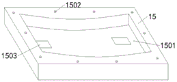
Further, install the apron on the processing base, be equipped with the inner chamber on the apron, be equipped with a plurality of fixed orificess two on the apron, fixed orificess two and the one-to-one correspondence of fixed orifices on the processing base still are equipped with the through-hole that equals with support column length, width on the apron.
Further, the radian of the groove and the inner cavity is consistent with the radian of an airplane door.
The utility model has the beneficial effects that:
1. the support columns are in threaded connection with the screw, and the motor drives the screw to rotate, so that the distance between the two support columns is changed, and the simulation cabin door is suitable for simulation cabin doors of different sizes.
2. First supporting shoe reciprocates on the support column through first telescopic cylinder, and the second supporting shoe reciprocates on the support column through second telescopic cylinder, is convenient for reduce occupation space when not using in first supporting shoe and the second supporting shoe withdrawal recess through telescopic cylinder.
3. Establish to the step face on one side of the first supporting block, be equipped with ejector pin and roof in the recess, the roof is the rubber slab, can protect the hatch door surface, supports the hatch door through step face and roof, and the fixed splint of rethread is fixed the hatch door, ensures that the course of working can not remove, the processing of being convenient for.
4. The processing base is provided with the cover plate, the cover plate is provided with the through hole corresponding to the support column, and when the processing equipment is not used, the first support plate and the second support plate are retracted into the groove and then covered with the cover plate, so that dust and other sundries are prevented from entering the equipment.
Drawings
The accompanying drawings, which are included to provide a further understanding of the utility model and are incorporated in and constitute a part of this specification, illustrate embodiments of the utility model and together with the description serve to explain the principles of the utility model and not to limit the utility model. In the drawings:
FIG. 1 is an isometric view of a processing base of the present invention;
FIG. 2 is a cross-sectional view of the interior of the process base of the present invention;
FIG. 3 is an isometric view of the support post of the present invention;
FIG. 4 is an isometric view of the support post of the present invention;
fig. 5 is an isometric view of the cover of the present invention.
Labeled as: 1. processing a base; 101. a groove; 102. a chute; 103. a first fixing hole; 2. a top plate; 3. a top rod; 4. a screw; 5. a universal wheel; 6. a motor; 7. a first telescopic cylinder; 8. a second telescopic cylinder; 9. a second support block; 10. a first support block; 11. a support pillar; 12. a rubber non-slip mat; 13. a third telescopic cylinder; 14. fixing the clamping plate; 15. a cover plate; 1501. an inner cavity; 1502. a second fixing hole; 1503. and a through hole.
Detailed Description
As shown in fig. 1-5, a flight simulation cabin door processing device comprises a processing base 1, a cover plate 15 and support columns 11, wherein the processing base 1 is provided with the cover plate 15, the cover plate 15 is provided with an inner cavity 1501, the cover plate 15 is provided with a plurality of fixing holes two 1502, the fixing holes two 1502 correspond to the fixing holes one 103 on the processing base 1, the cover plate 15 is further provided with through holes with the length and the width equal to those of the support columns 11, the radians of the groove 101 and the inner cavity 1501 are consistent with the radian of an airplane cabin door, the bottom end of the processing base 1 is provided with a universal wheel 1503, the processing base 1 is provided with a plurality of fixing holes one 103, the processing base 1 is internally provided with the groove 101, four ejector rods 3 are uniformly arranged in the groove 101, the lengths of the ejector rods 3 are adjustable, springs are arranged at the bottom ends of the ejector rods 3, the ejector rods 3 are positioned between the two support columns 11, the ejector rods 3 are provided with top plates 2, the top plates 2 are rubber plates, the radians of the surfaces of the top plates 2 are the same as those of the simulation cabin door, a chute 102 is arranged in the groove 101, a screw 4 is movably arranged in the chute 102, a motor 6 is arranged on one side of the processing base 1, an output shaft of the motor 6 is connected with the screw 4, two support columns 11 are connected with the screw 4 in a threaded manner, a first support block 10 and a second support block 9 are sleeved on the support columns 11, a first telescopic cylinder 7 is arranged on one side of each support column 11, the top end of a telescopic rod of each first telescopic cylinder 7 is arranged at the bottom end of the corresponding first support block 10, the first support block 10 moves up and down on the support columns 11, a step surface is arranged on one side of each first support block 10, rubber anti-skid pads 12 are arranged on the surface of the step surface of each first support block 10, the second support blocks 9 are positioned above the first support blocks 10, the second support blocks 9 and the first support blocks 10 are connected through the second telescopic cylinders 8, the length of the second support blocks 9 is greater than that of the first support blocks 10, and the second support blocks 9 are flush with one sides of the step surfaces of the first support blocks 10, third telescopic cylinders 13 are symmetrically arranged on the second supporting block 9, fixed splints 14 are arranged on the third telescopic cylinders 13, and rubber anti-skid pads 12 are arranged on the inner side surfaces of the fixed splints 14 arranged on the second supporting block 9.
Referring to fig. 1-5, the support columns 11 are in threaded connection with the screw rod 4, the thread turning directions of the two support columns 11 are opposite, when the screw rod 4 is driven by the motor 6 to rotate, the two support columns 11 move oppositely or oppositely, the horizontal distance between the two support columns 11 is adjustable, so that the installation and disassembly of the cabin door are facilitated, the ejector rods 3 installed in the grooves 101 are telescopic rods, springs are installed at the bottom ends of the ejector rods 3, the top plate 2 vertically supports the cabin door and then is fixed through the first support blocks 10 and the second support blocks 9 on the support columns 11, and the top plate 2 is an arc-shaped rubber plate, so that the surface of the cabin door can be protected from abrasion while the support force of the top plate is ensured; the screw rod 4 rotates the two supporting columns 11 to move relatively, the first telescopic cylinder 7 adjusts the vertical position of the first supporting block 10, according to the length adjustment of the hatch door, one side of the first supporting block 10 is a step surface, meanwhile, the step surface has a certain radian, the height of the first supporting block 10 is less than the thickness of the hatch door, one side of the clamping surface of the second supporting block 9 is a cambered surface, so that the second supporting block 9 can clamp the hatch door conveniently, after the vertical position of the cabin door is accurately fixed through the first supporting block 10 and the second supporting block 9, the third telescopic cylinder 13 pushes the fixed clamping plate 14 to move back and forth to fix the front and back direction of the cabin door, so that the cabin door can be stably supported by equipment in subsequent processing, rubber anti-skidding pads 12 are arranged on one side of the step surface of the first supporting block 10 and the inner side of the fixed clamping plate 14, the surface of the cabin door can be protected, the cabin door can be prevented from slipping, and the stability of processing equipment can be ensured; install apron 15 on the processing base 1, when first supporting shoe 10 and second supporting shoe 9 moved extreme position (supporting shoe 11 bottom), the degree of depth that the bottom distance of supporting shoe 11 to first supporting shoe 10 was greater than spout 102, the distance of first supporting shoe 10 bottom to second supporting shoe 9 top is less than the distance of recess 101 peak to the minimum of inner chamber 1501, through fixed orifices two 1502 and fixed orifices one 103 with apron 15 fixed mounting on the processing base 1, effectively prevent impurity such as dust from getting into in the equipment, the universal wheel 5 of processing base 1 bottom installation is convenient for the removal of processing equipment, labour saving and time saving during the operation.
When the utility model is used, the height of the mandril 3 is adjusted, the initial position of the support rods 11 is positioned at two sides, the cabin door is placed on the top plate 2, the positions of the support rods 11 and the first support block 10 are adjusted according to the current height of the cabin door, the motor 6 is started, the motor 6 drives the screw rod 4 to rotate, at the moment, the two support rods 11 move oppositely, the first telescopic cylinder 7 pushes the first support block 10 to the bottom end of the cabin door, meanwhile, the second telescopic cylinder 8 pulls the second support block 9 downwards to the top end of the cabin door, the first support block 10 and the second support block 9 further fix the cabin door in the vertical direction, then the third telescopic cylinder 13 moves the fixed clamping plate 14 to the direction of the cabin door, the fixed clamping plate 14 fixedly clamps the front and back direction of the cabin door, the fixed clamping plate 14, the second support plate 9 and the support rods 11 are sequentially loosened, the cabin door is taken out, and when the equipment is not used, the first support plate 10 and the second support plate 9 move to the bottom of the support rods 11, the cover plate 15 passes through the support column 11 and is installed on the processing base 1 to prevent dust and impurities from entering.
Although the present invention has been described in detail with reference to the foregoing embodiments, those skilled in the art will understand that various changes, modifications and substitutions can be made without departing from the spirit and scope of the utility model as defined by the appended claims. Any modification, equivalent replacement, or improvement made within the spirit and principle of the present invention should be included in the protection scope of the present invention.
Claims (7)
1. A flight simulation cabin door processing device comprises a processing base (1), a cover plate (15) and support columns (11), and is characterized in that universal wheels (5) are installed at the bottom end of the processing base (1), a plurality of first fixing holes (103) are formed in the processing base (1), a groove (101) is formed in the processing base (1), a sliding groove (102) is formed in the groove (101), a screw rod (4) is movably installed in the sliding groove (102), a motor (6) is installed on one side of the processing base (1), an output shaft of the motor (6) is connected with the screw rod (4), two support columns (11) are in threaded connection with the screw rod (4), a first support block (10) and a second support block (9) are sleeved on each support column (11), a first telescopic cylinder (7) is installed on one side of each support column (11), and the top end of a telescopic rod of each first telescopic cylinder (7) is installed at the bottom end of the first support block (10), first supporting shoe (10) reciprocate on support column (11), second supporting shoe (9) are located first supporting shoe (10) top, and second supporting shoe (9) and first supporting shoe (10) are connected through second telescopic cylinder (8), and third telescopic cylinder (13) are installed to the symmetry on second supporting shoe (9), install solid fixed splint (14) on third telescopic cylinder (13), and the inboard surface mounting of solid fixed splint (14) has rubber slipmat (12).
2. The flight simulation cabin door processing equipment according to claim 1, characterized in that four ejector rods (3) are uniformly installed in the groove (101), the lengths of the ejector rods (3) are adjustable, the bottom ends of the ejector rods (3) are provided with springs, the ejector rods (3) are located between two support columns (11), and the ejector rods (3) are provided with top plates (2).
3. The flight simulation cabin door processing equipment according to claim 2, characterized in that the top plate (2) is a rubber plate, and the radian of the surface of the top plate (2) is the same as that of the simulation cabin door.
4. The flight simulation cabin door processing equipment according to claim 1, characterized in that one side of the first supporting block (10) is a step surface, and rubber non-slip pads (12) are arranged on the surface of the step surface of the first supporting block (10).
5. The flight simulation cabin door processing equipment according to claim 1, characterized in that the length of the second support block (9) is greater than the length of the first support block (10), the second support block (9) being flush with the side of the step face of the first support block (10).
6. The flight simulation cabin door processing equipment according to claim 1, characterized in that a cover plate (15) is installed on the processing base (1), an inner cavity (1501) is formed in the cover plate (15), a plurality of second fixing holes (1502) are formed in the cover plate (15), the second fixing holes (1502) correspond to the first fixing holes (103) in the processing base (1) one by one, and through holes (1503) equal to the length and width of the supporting columns (11) are further formed in the cover plate (15).
7. The flight simulator door processing device according to claim 1, characterized in that the curvature of the groove (101) and the inner cavity (1501) corresponds to the simulated cabin door curvature.
Priority Applications (1)
| Application Number | Priority Date | Filing Date | Title |
|---|---|---|---|
| CN202120547070.4U CN216327551U (en) | 2021-03-17 | 2021-03-17 | Flight simulation cabin door processing equipment |
Applications Claiming Priority (1)
| Application Number | Priority Date | Filing Date | Title |
|---|---|---|---|
| CN202120547070.4U CN216327551U (en) | 2021-03-17 | 2021-03-17 | Flight simulation cabin door processing equipment |
Publications (1)
| Publication Number | Publication Date |
|---|---|
| CN216327551U true CN216327551U (en) | 2022-04-19 |
Family
ID=81128319
Family Applications (1)
| Application Number | Title | Priority Date | Filing Date |
|---|---|---|---|
| CN202120547070.4U Expired - Fee Related CN216327551U (en) | 2021-03-17 | 2021-03-17 | Flight simulation cabin door processing equipment |
Country Status (1)
| Country | Link |
|---|---|
| CN (1) | CN216327551U (en) |
-
2021
- 2021-03-17 CN CN202120547070.4U patent/CN216327551U/en not_active Expired - Fee Related
Similar Documents
| Publication | Publication Date | Title |
|---|---|---|
| CN203472415U (en) | Automobile tire mounting and demounting device | |
| CN206509789U (en) | A kind of clamping device punched for casting | |
| CN216327551U (en) | Flight simulation cabin door processing equipment | |
| CN219705068U (en) | Special maintenance frock of aeroengine radome fairing | |
| CN111015827B (en) | Integral type gantry water cutting machine capable of machining slope inclination angle | |
| CN211386543U (en) | Mould for hardware processing | |
| CN210060480U (en) | Quick clamping and positioning fixture of casting special control machining center | |
| CN111546678A (en) | Vertical single-station post-engineering tire inflation device | |
| CN219113914U (en) | Quick clamping device for hydraulic cylinder assembly | |
| CN214719720U (en) | Stamping device for automobile central control instrument framework | |
| CN219026641U (en) | Supporting platform for die carrier machining | |
| CN220179899U (en) | EPP packing box forming device | |
| CN215550213U (en) | Quick demoulding clamp for automobile center console | |
| CN210774132U (en) | Bearing in-place detection mechanism | |
| CN219786692U (en) | Auxiliary positioning device for milling machine processing | |
| CN215855789U (en) | Full-automatic double-tool-bit glass cutting machine | |
| CN220007349U (en) | Automobile floor beam assembly clamp | |
| CN212121796U (en) | Electric automatic drilling machine | |
| CN219255121U (en) | Surface grinding machine for mold processing with good anti-floating dust effect | |
| CN210046352U (en) | Clamping and fixing platform equipment of tool | |
| CN219617102U (en) | Pneumatic pressure device with adjustable distance | |
| CN219788402U (en) | Six-axis robot operation table with lifting mechanism | |
| CN219155119U (en) | Placer is used in tire production | |
| CN215356525U (en) | Automobile die machining is with getting rid of rim charge device | |
| CN220488812U (en) | A installing support for network system is integrated |
Legal Events
| Date | Code | Title | Description |
|---|---|---|---|
| GR01 | Patent grant | ||
| GR01 | Patent grant | ||
| CF01 | Termination of patent right due to non-payment of annual fee |
Granted publication date: 20220419 |
|
| CF01 | Termination of patent right due to non-payment of annual fee |