CN216321532U - Material mixing device for building engineering - Google Patents
Material mixing device for building engineering Download PDFInfo
- Publication number
- CN216321532U CN216321532U CN202122968805.3U CN202122968805U CN216321532U CN 216321532 U CN216321532 U CN 216321532U CN 202122968805 U CN202122968805 U CN 202122968805U CN 216321532 U CN216321532 U CN 216321532U
- Authority
- CN
- China
- Prior art keywords
- box
- fixed mounting
- box body
- puddler
- material mixing
- Prior art date
- Legal status (The legal status is an assumption and is not a legal conclusion. Google has not performed a legal analysis and makes no representation as to the accuracy of the status listed.)
- Active
Links
Images


Landscapes
- Mixers Of The Rotary Stirring Type (AREA)
Abstract
The utility model relates to a material mixing device for constructional engineering, which comprises a box body, wherein a first stirring mechanism with one end penetrating through and extending into the box body is arranged at the bottom of the box body, a driving mechanism is arranged at the top of the box body, a second stirring mechanism with one end penetrating through and extending into the box body is arranged on the driving mechanism, a cleaning mechanism is arranged on the right side of the box body, and a drying mechanism is arranged on the front side of the box body. This material mixing arrangement for building engineering, actuating drive motor takes the threaded rod motion through the actuating mechanism who sets up, the reciprocal threaded rod of taking has the screw slider to move left or right, the screw slider takes contact block and contacts with the swash plate, thereby make the second rabbling mechanism of one side upwards, the second rabbling mechanism of opposite side is downward, along with actuating mechanism's operation, can take the reciprocal reciprocating of second rabbling mechanism to reciprocate, thereby the quick raw materials with in the box mixes fully, so, the purpose of high-efficient mixture has been realized.
Description
Technical Field
The utility model relates to the technical field of building engineering material mixing, in particular to a material mixing device for building engineering.
Background
The building engineering refers to an engineering entity formed by the construction of various building buildings and their auxiliary facilities and the installation of lines, pipes and equipment matched with them, wherein the building buildings refer to the engineering which has top covers, beams, columns, walls, foundations and can form internal spaces and meet the requirements of people for production, living, study and public activities.
Need use material mixing device in the building engineering construction to mix the raw materials together, current material mixing device need spend longer time just can be with the inside material intensive mixing of device, and the efficiency of mixing is lower, has reduced building engineering's efficiency of construction.
SUMMERY OF THE UTILITY MODEL
Aiming at the defects of the prior art, the utility model provides a material mixing device for constructional engineering, which has the advantages of efficient mixing and the like, and solves the problem that the conventional material mixing device needs to spend longer time to fully mix materials in the device.
In order to achieve the purpose, the utility model provides the following technical scheme: a material mixing device for constructional engineering comprises a box body, wherein a first stirring mechanism with one end penetrating through and extending into the box body is arranged at the bottom of the box body, a driving mechanism is arranged at the top of the box body, a second stirring mechanism with one end penetrating through and extending into the box body is arranged on the driving mechanism, a cleaning mechanism is arranged on the right side of the box body, and a drying mechanism is arranged on the front side of the box body;
actuating mechanism includes mounting panel, driving motor, threaded rod, thread sliding block, fly leaf, swash plate and contact piece, the top fixed mounting of box has quantity to be two mounting panels, right side the left side fixed mounting of mounting panel has driving motor, driving motor's output fixed mounting has one end and left side mounting panel swing joint's threaded rod, the outside threaded connection of threaded rod has the thread sliding block, the top of box and the rear side movable mounting who is located the threaded rod have the fly leaf, the bottom of fly leaf and the top fixed mounting who is located the threaded rod have quantity to be two swash plates, the top fixed mounting of thread sliding block has the contact piece that one end and swash plate contacted.
Further, first rabbling mechanism includes motor casing, first agitator motor, first puddler and first stirring vane, the bottom fixed mounting of box has the motor casing, the interior diapire fixed mounting of motor casing has first agitator motor, first agitator motor's output fixed mounting has one end to run through and extend to the inside first puddler of box, the outside fixed mounting of first puddler has first stirring vane.
Further, second rabbling mechanism is including installation piece, second agitator motor, second puddler and second stirring vane, the positive movable mounting of fly leaf has quantity to be two installation pieces, two the equal fixed mounting in bottom of installation piece has second agitator motor, two the equal fixed mounting in output of second agitator motor has one end to run through and extend to the inside second puddler of box, two the equal fixed mounting in the outside of second puddler has second stirring vane, two the second puddler is located the left and right sides of first puddler respectively.
Further, wiper mechanism includes water pump, inlet tube, outlet pipe, shower nozzle and annular tube, the right side fixed mounting of box has the water pump, the water inlet intercommunication of water pump has the inlet tube, the delivery port intercommunication of water pump has one end to run through and extend to the inside outlet pipe of box, the left side intercommunication of outlet pipe has cup joints the annular tube in the outside of second puddler, the bottom intercommunication of annular tube has the shower nozzle.
Further, stoving mechanism includes air heater and air-out pipe, the positive fixed mounting of box has including the air heater, the air outlet intercommunication of including the air heater has one end to run through and extend to the inside air-out pipe of box.
Furthermore, the connection relation of the movable plate and the mounting block is hinged, and a supporting plate hinged with the movable plate is fixedly mounted at the top of the box body.
Further, the left side intercommunication of box has the loading hopper, the right side of box and the below intercommunication that is located the water pump have the discharging pipe, the outside of discharging pipe is provided with the bleeder valve.
Compared with the prior art, the technical scheme of the application has the following beneficial effects:
1. this material mixing arrangement for building engineering, actuating drive motor takes the threaded rod motion through the actuating mechanism who sets up, the reciprocal threaded rod of taking has the screw slider to move left or right, the screw slider takes contact block and contacts with the swash plate, thereby make the second rabbling mechanism of one side upwards, the second rabbling mechanism of opposite side is downward, along with actuating mechanism's operation, can take the reciprocal reciprocating of second rabbling mechanism to reciprocate, thereby the quick raw materials with in the box mixes fully, so, the purpose of high-efficient mixture has been realized.
2. This material mixing arrangement for building engineering, through wiper mechanism and the stoving mechanism that sets up, when using, can start the water pump and carry shower nozzle department with water, spout water through the shower nozzle and wash the residue of box inside clean, start the air heater and blow hot-blast inside to the box through the tuber pipe, make the box can rapid draing, so, realized the purpose of box self-cleaning stoving.
Drawings
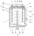
FIG. 1 is a schematic structural view of the present invention;
FIG. 2 is an enlarged view taken at A of FIG. 1 in accordance with the present invention;
fig. 3 is a front view of the present invention.
In the figure: the device comprises a box body 1, a first stirring mechanism 2, a motor shell 21, a first stirring motor 22, a first stirring rod 23, a first stirring blade 24, a driving mechanism 3, a mounting plate 31, a driving motor 32, a threaded rod 33, a threaded slider 34, a movable plate 35, a sloping plate 36, a contact block 37, a second stirring mechanism 4, a mounting block 41, a second stirring motor 42, a second stirring rod 43, a second stirring blade 44, a cleaning mechanism 5, a water pump 51, a water inlet pipe 52, a water outlet pipe 53, a spray head 54, a ring pipe 55, a drying mechanism 6, a hot air blower 61 and an air outlet pipe 62.
Detailed Description
The technical solutions in the embodiments of the present invention will be clearly and completely described below with reference to the drawings in the embodiments of the present invention, and it is obvious that the described embodiments are only a part of the embodiments of the present invention, and not all of the embodiments. All other embodiments, which can be derived by a person skilled in the art from the embodiments given herein without making any creative effort, shall fall within the protection scope of the present invention.
Referring to fig. 1-3, the material mixing device for construction engineering in this embodiment includes a box 1, a first stirring mechanism 2 having one end penetrating and extending into the box 1 is disposed at the bottom of the box 1, a driving mechanism 3 is disposed at the top of the box 1, a second stirring mechanism 4 having one end penetrating and extending into the box 1 is disposed on the driving mechanism 3, a cleaning mechanism 5 is disposed at the right side of the box 1, and a drying mechanism 6 is disposed at the front side of the box 1;
the driving mechanism 3 comprises a mounting plate 31, a driving motor 32, a threaded rod 33, a threaded slider 34, a movable plate 35, inclined plates 36 and contact blocks 37, wherein two mounting plates 31 are fixedly mounted at the top of the box body 1, the driving motor 32 is fixedly mounted at the left side of the right mounting plate 31, the threaded rod 33 with one end movably connected with the left mounting plate 31 is fixedly mounted at the output end of the driving motor 32, the threaded slider 34 is connected with the outer side of the threaded rod 33 through threads, the movable plate 35 is movably mounted at the top of the box body 1 and positioned at the rear side of the threaded rod 33, two inclined plates 36 are fixedly mounted at the bottom of the movable plate 35 and positioned above the threaded rod 33, the contact blocks 37 with one ends contacting with the inclined plates 36 are fixedly mounted at the top of the threaded slider 34, when the driving motor 32 can be started to drive the threaded rod 33 to move, and the threaded rod 33 drives the threaded slider 34 to move leftwards or rightwards in a reciprocating manner, the screw slider 34 brings the contact block 37 into contact with the inclined plate 36, so that the second stirring mechanism 4 on one side faces upward and the second stirring mechanism 4 on the other side faces downward to provide a driving force for the movement of the second stirring mechanism 4.
In this embodiment, the first stirring mechanism 2 includes a motor casing 21, a first stirring motor 22, a first stirring rod 23 and a first stirring blade 24, the bottom fixed mounting of the box 1 has the motor casing 21, the inner bottom wall fixed mounting of the motor casing 21 has the first stirring motor 22, the output end fixed mounting of the first stirring motor 22 has the first stirring rod 23 of which one end runs through and extends to the box 1, the outside fixed mounting of the first stirring rod 23 has the first stirring blade 24, when in use, start the first stirring motor 42 and drive the first stirring rod 43 to rotate, and the first stirring rod 43 drives the first stirring blade 44 to perform stirring operation.
In this embodiment, the second stirring mechanism 4 includes two mounting blocks 41, two second stirring motors 42, two second stirring rods 43 and two second stirring blades 44, the front surface of the movable plate 35 is movably mounted with the two mounting blocks 41, the bottoms of the two mounting blocks 41 are both fixedly mounted with the second stirring motors 42, the output ends of the two second stirring motors 42 are both fixedly mounted with the second stirring rods 43, one ends of the second stirring rods 43 penetrate through and extend into the box 1, the outer sides of the two second stirring rods 43 are both fixedly mounted with the second stirring blades 44, the two second stirring rods 43 are respectively located at the left and right sides of the first stirring rod 23, in use, the second stirring motor 42 is started to drive the second stirring rod 43 to rotate, the second stirring rod 43 drives the second stirring blade 44, and with the operation of the driving mechanism 3, the second stirring mechanism 4 can be driven to reciprocate up and down, so that the raw materials in the box body 1 can be quickly and fully mixed.
In this embodiment, the cleaning mechanism 5 includes a water pump 51, a water inlet pipe 52, a water outlet pipe 53, a spray head 54 and a ring pipe 55, the water pump 51 is fixedly installed on the right side of the box body 1, a water inlet of the water pump 51 is communicated with the water inlet pipe 52, a water outlet of the water pump 51 is communicated with the water outlet pipe 53 with one end penetrating through and extending to the inside of the box body 1, the ring pipe 55 sleeved outside the second stirring rod 43 is communicated with the left side of the water outlet pipe 53, the spray head 54 is communicated with the bottom of the ring pipe 55, when the cleaning mechanism is used, the water inlet pipe 52 is communicated with a tap water pipeline, the water pump 51 is started to convey water to the spray head 54, and water is sprayed out through the spray head 54 to clean residues inside the box body 1.
In this embodiment, stoving mechanism 6 includes air heater 61 and play tuber pipe 62, and the front fixed mounting of box 1 has including air heater 61, and the air outlet intercommunication that includes air heater 61 has one end to run through and extend to the inside play tuber pipe 62 of box 1, and when using, can start air heater 61 with hot-blast through going out tuber pipe 62 and blow to box 1 inside, make box 1 can rapid draing.
In this embodiment, the movable plate 35 is hinged to the mounting block 41, and a supporting plate hinged to the movable plate 35 is fixedly mounted on the top of the box 1.
In this embodiment, the left side intercommunication of box 1 has the loading hopper, and when using, the person of facilitating the use is toward the inside raw materials that adds of box 1, and the right side of box 1 just is located the below intercommunication of water pump 51 has the discharging pipe, and the outside of discharging pipe is provided with the bleeder valve, when using, opens the bleeder valve and can carry out ejection of compact operation by the discharging pipe.
It should be noted that the top of the box body 1 is provided with a limiting groove, and a limiting block with one end fixedly connected with the threaded sliding block 34 is movably mounted inside the limiting groove.
The working principle of the above embodiment is as follows:
(1) adding raw materials into the box body 1 through the charging hopper, starting the first stirring motor 42 to drive the first stirring rod 43 to rotate, and driving the first stirring blade 44 by the first stirring rod 43 to perform stirring operation;
(2) the driving motor 32 is started to drive the threaded rod 33 to move, the threaded rod 33 drives the threaded sliding block 34 to reciprocate and move leftwards or rightwards, the threaded sliding block 34 drives the contact block 37 to contact with the inclined plate 36, so that the second stirring mechanism 4 on one side faces upwards, the second stirring mechanism 4 on the other side faces downwards, the second stirring motor 42 is started, and the second stirring blade 44 is driven to quickly and fully mix the raw materials in the box body 1;
(3) after mixing, open the bleeder valve and can carry out ejection of compact operation by the discharging pipe, start water pump 51 and carry shower nozzle 54 department with water, spout the residue of the inside of box 1 clean through shower nozzle 54 with water, start hot-blast air heater 61 with hot-blast through going out tuber pipe 62 and blow to the box 1 inside, make box 1 can rapid draing.
It is noted that, herein, relational terms such as first and second, and the like may be used solely to distinguish one entity or action from another entity or action without necessarily requiring or implying any actual such relationship or order between such entities or actions. Also, the terms "comprises," "comprising," or any other variation thereof, are intended to cover a non-exclusive inclusion, such that a process, method, article, or apparatus that comprises a list of elements does not include only those elements but may include other elements not expressly listed or inherent to such process, method, article, or apparatus. Without further limitation, an element defined by the phrase "comprising an … …" does not exclude the presence of other identical elements in a process, method, article, or apparatus that comprises the element.
Although embodiments of the present invention have been shown and described, it will be appreciated by those skilled in the art that changes, modifications, substitutions and alterations can be made in these embodiments without departing from the principles and spirit of the utility model, the scope of which is defined in the appended claims and their equivalents.
Claims (7)
1. The utility model provides a material mixing arrangement for building engineering, includes box (1), its characterized in that: a first stirring mechanism (2) with one end penetrating through and extending into the box body (1) is arranged at the bottom of the box body (1), a driving mechanism (3) is arranged at the top of the box body (1), a second stirring mechanism (4) with one end penetrating through and extending into the box body (1) is arranged on the driving mechanism (3), a cleaning mechanism (5) is arranged on the right side of the box body (1), and a drying mechanism (6) is arranged on the front side of the box body (1);
actuating mechanism (3) are including mounting panel (31), driving motor (32), threaded rod (33), screw thread slider (34), fly leaf (35), swash plate (36) and contact piece (37), the top fixed mounting of box (1) has mounting panel (31) that quantity is two, right side the left side fixed mounting of mounting panel (31) has driving motor (32), the output fixed mounting of driving motor (32) has one end and left side mounting panel (31) swing joint's threaded rod (33), the outside threaded connection of threaded rod (33) has screw thread slider (34), the top of box (1) and the rear side movable mounting who is located threaded rod (33) have fly leaf (35), the bottom of fly leaf (35) and the top fixed mounting that is located threaded rod (33) have quantity as two swash plate (36), the top fixed mounting of screw thread slider (34) has the contact piece (36) that one end and swash plate (36) contacted (contact piece(s) (contact piece (37) 37).
2. The material mixing device for construction engineering according to claim 1, wherein: first rabbling mechanism (2) include motor casing (21), first agitator motor (22), first puddler (23) and first stirring vane (24), the bottom fixed mounting of box (1) has motor casing (21), the interior diapire fixed mounting of motor casing (21) has first agitator motor (22), the output fixed mounting of first agitator motor (22) has one end to run through and extend to box (1) inside first puddler (23), the outside fixed mounting of first puddler (23) has first stirring vane (24).
3. The material mixing device for construction engineering according to claim 2, wherein: second rabbling mechanism (4) are including installation piece (41), second agitator motor (42), second puddler (43) and second stirring vane (44), the positive movable mounting of fly leaf (35) has quantity to be two installation piece (41), two the equal fixed mounting in bottom of installation piece (41) has second agitator motor (42), two the equal fixed mounting in output of second agitator motor (42) has one end to run through and extend to inside second puddler (43) of box (1), two the equal fixed mounting in the outside of second puddler (43) has second stirring vane (44), two second puddler (43) are located the left and right sides of first puddler (23) respectively.
4. A material mixing device for construction engineering according to claim 3, characterized in that: cleaning mechanism (5) include water pump (51), inlet tube (52), outlet pipe (53), shower nozzle (54) and annular tube (55), the right side fixed mounting of box (1) has water pump (51), the water inlet intercommunication of water pump (51) has inlet tube (52), the delivery port intercommunication of water pump (51) has one end to run through and extends to box (1) inside outlet pipe (53), the left side intercommunication of outlet pipe (53) has cup jointed annular tube (55) in second puddler (43) outside, the bottom intercommunication of annular tube (55) has shower nozzle (54).
5. The material mixing device for construction engineering according to claim 1, wherein: drying mechanism (6) include air heater (61) and air-out pipe (62), the front fixed mounting of box (1) has air heater (61) of drawing together, draw together the air outlet intercommunication of air heater (61) and have one end to run through and extend to inside air-out pipe (62) of box (1).
6. A material mixing device for construction engineering according to claim 3, characterized in that: the movable plate (35) is hinged to the mounting block (41), and a supporting plate hinged to the movable plate (35) is fixedly mounted at the top of the box body (1).
7. The material mixing device for construction engineering according to claim 4, wherein: the left side intercommunication of box (1) has the loading hopper, the right side of box (1) just is located the below intercommunication of water pump (51) and has the discharging pipe, the outside of discharging pipe is provided with the bleeder valve.
Priority Applications (1)
| Application Number | Priority Date | Filing Date | Title |
|---|---|---|---|
| CN202122968805.3U CN216321532U (en) | 2021-11-30 | 2021-11-30 | Material mixing device for building engineering |
Applications Claiming Priority (1)
| Application Number | Priority Date | Filing Date | Title |
|---|---|---|---|
| CN202122968805.3U CN216321532U (en) | 2021-11-30 | 2021-11-30 | Material mixing device for building engineering |
Publications (1)
| Publication Number | Publication Date |
|---|---|
| CN216321532U true CN216321532U (en) | 2022-04-19 |
Family
ID=81155407
Family Applications (1)
| Application Number | Title | Priority Date | Filing Date |
|---|---|---|---|
| CN202122968805.3U Active CN216321532U (en) | 2021-11-30 | 2021-11-30 | Material mixing device for building engineering |
Country Status (1)
| Country | Link |
|---|---|
| CN (1) | CN216321532U (en) |
-
2021
- 2021-11-30 CN CN202122968805.3U patent/CN216321532U/en active Active
Similar Documents
| Publication | Publication Date | Title |
|---|---|---|
| CN217043864U (en) | Belt cleaning device of batching jar | |
| CN110666965A (en) | Cement mortar mixer for building | |
| CN208615052U (en) | A kind of cement plaster blender for building | |
| CN112127254A (en) | Road cementation of fissures device for municipal works | |
| CN205617744U (en) | Automatic wash mortar flush coater | |
| CN216321532U (en) | Material mixing device for building engineering | |
| CN111745815B (en) | Mortar preparation facilities convenient to it is clean | |
| CN214971809U (en) | Energy-saving emission-reducing centrifugal spray dryer | |
| CN217016226U (en) | Mixing device of efficient glue-pouring machine | |
| CN110397250A (en) | A kind of wall coating for building spray equipment | |
| CN211104761U (en) | Take cleaning function's mixer | |
| CN214772955U (en) | Mixing device with self-cleaning function for mixing mineral powder in concrete | |
| CN211640471U (en) | Aerated concrete block batching jar | |
| CN211329037U (en) | Construction is with agitating unit convenient to wash and dismantle | |
| CN220559604U (en) | Mortar spraying device for anti-corrosion engineering | |
| CN215038899U (en) | Cement mixing plant for housing construction engineering | |
| CN220741680U (en) | Energy-saving environment-friendly ready-mixed concrete mixing plant | |
| CN220464294U (en) | Mixer convenient to clearance stirring vane | |
| CN209504509U (en) | One kind is convenient for clean single horizontal axis concrete mixer | |
| CN220194852U (en) | Vertical self-cleaning reaction kettle | |
| CN216224165U (en) | Cement manufacture line dosing unit | |
| CN216505914U (en) | Mixer is used in concrete block production with clean function | |
| CN216321670U (en) | Agitating unit is used in impregnated paper production | |
| CN115491951B (en) | Asphalt concrete composite stirring equipment | |
| CN214809966U (en) | Agitated vessel is used in gesso processing |
Legal Events
| Date | Code | Title | Description |
|---|---|---|---|
| GR01 | Patent grant | ||
| GR01 | Patent grant |