CN216294469U - Electric power-assisted chair capable of moving and lifting - Google Patents
Electric power-assisted chair capable of moving and lifting Download PDFInfo
- Publication number
- CN216294469U CN216294469U CN202122548030.4U CN202122548030U CN216294469U CN 216294469 U CN216294469 U CN 216294469U CN 202122548030 U CN202122548030 U CN 202122548030U CN 216294469 U CN216294469 U CN 216294469U
- Authority
- CN
- China
- Prior art keywords
- seat
- sliding
- lifting
- chassis
- sides
- Prior art date
- Legal status (The legal status is an assumption and is not a legal conclusion. Google has not performed a legal analysis and makes no representation as to the accuracy of the status listed.)
- Active
Links
Images


Landscapes
- Special Chairs (AREA)
Abstract
The utility model discloses a movable lifting electric power-assisted chair which comprises a chassis, a sliding plate, a lifting structure and a bracket, wherein the sliding plate can slide on the chassis; the two sides of the chassis are provided with side plates and universal wheels arranged on the two sides of the side plates, and the sliding plate is connected with the chassis in a sliding manner through a sliding mechanism; the lifting structure comprises an electric push rod, a lifting seat arranged on the electric push rod, an electric device arranged in the lifting seat, a lifting control rod arranged on the lifting seat and a bracket connected with the two sides of the lifting seat; the brackets at two sides are respectively hinged with the connecting rod frames, and the connecting rod frames at two sides are connected with seats; the seat comprises a back cushion and a seat cushion which are mutually closed, the connecting rod frames are provided with locking and closing devices, and the two connecting rod frames can be locked, closed or opened by controlling the locking and closing devices, so that the seat cushion and the back cushion can be locked, closed or opened. The utility model can adjust the height and the horizontal position of the chair, and is convenient for a user to perform auxiliary movement.
Description
Technical Field
The utility model relates to the technical field of power-assisted chairs, in particular to a movable lifting electric power-assisted chair.
Background
The helping hand chair is the mechanical device that helps take care of the old person, can provide help for taking care of nursing old person and patient that the action is inconvenient. The old people are inconvenient to move in living and living, and the old people often have difficulty in getting up when living at home and also have the phenomena of lumbago and leg numbness. With the aging and aging of the population in China, the number of disabled and sick old people in China is increasing. In life, people often see wounded people, old people and severe patients, and people are inconvenient to move and need to be nursed due to extremely weak physical strength. Particularly, when the toilet is needed, the movement is difficult, which brings great inconvenience to nursing staff, so that people often need to support the toilet smoothly. However, if the nursing staff is not strong enough or the old or the patient with inconvenient movement is overweight, the old or the patient can cause difficulty in supporting the medicine, and the old or the patient can seriously fall down to cause secondary injury.
Need the helping hand chair to assist when using to the old person and the patient of looking after leg and foot inconvenience and remove, current helping hand chair structural support poor stability, the trouble leads to looking after the old person and the patient of leg and foot inconvenience when using of back switch, and the bottom of the seat of helping hand chair is too high difficult to remove to old person or patient on bed or sofa.
Disclosure of Invention
The technical problem to be solved by the utility model is to provide a movable lifting electric power-assisted chair which has high structural support stability and a simple back switch structure, can adjust the height and the horizontal position of the chair, and can be convenient for old people and patients with inconvenient legs and feet to move in an auxiliary manner.
In order to solve the technical problem, the utility model provides a movable lifting electric power-assisted chair which comprises a chassis, a sliding plate, a lifting structure and a bracket, wherein the sliding plate can slide on the chassis;
the two sides of the chassis are provided with side plates and universal wheels arranged on the two sides of the side plates, and the sliding plate is connected with the chassis in a sliding manner through a sliding mechanism;
the lifting structure comprises an electric push rod, a lifting seat arranged on the electric push rod, an electric device arranged in the lifting seat, a lifting control rod arranged on the lifting seat and a bracket connected with the two sides of the lifting seat;
the electric device is connected with the electric push rod, the lifting control rod is used for controlling the work of the electric device, the brackets at two sides are respectively hinged with the connecting rod frames, and the connecting rod frames at two sides are connected with the seats;
the seat comprises two back cushions and two seat cushions, wherein the back cushions are closed mutually;
the connecting rod frames are provided with locking and closing devices, and the two connecting rod frames can be locked, closed or opened by controlling the locking and closing devices, so that the seat cushion and the back cushion can be locked, closed or opened.
As an improvement of the scheme, the sliding mechanism comprises a sliding rail shaft and shaft sleeves, the sliding rail shaft is respectively arranged in the side plates at the two sides, and the shaft sleeves are respectively arranged at the two ends of the sliding plate; the shaft sleeve is sleeved in the slide rail shaft, and the slide plate can slide relative to the chassis through the sliding connection of the slide rail shaft and the shaft sleeve.
As an improvement of the above scheme, the locking closing device comprises a first closing plate, a second closing plate and a locking switch, wherein the locking switch is installed on the first closing plate, and the first closing plate and the second closing plate are respectively connected with the connecting rod frames at two sides and are also respectively connected with the back cushion; the first closing plate and the second closing plate can be closed or opened relatively by rotating the locking switch.
As an improvement of the above scheme, the locking switch is further provided with a locking sliding buckle, the locking sliding buckle is arranged in the first closing plate, and a clamping groove corresponding to the locking sliding buckle is arranged in the second closing plate; through rotating the locking switch, the locking slider can be connected with or separated from the clamping groove in a clamping manner, so that the first closing plate and the second closing plate are locked, closed or opened.
As an improvement of the scheme, a buckle structure is arranged between the sliding plate and the chassis, and the buckle structure can fixedly connect the sliding plate and the chassis.
As an improvement of the scheme, the buckle structure comprises a pedal and a buckle, the pedal is arranged on the sliding plate, the pedal is provided with a buckle groove, and the buckle is arranged on the chassis; the buckle groove is connected with the buckle in a clamping mode, the sliding plate can be fixedly connected with the chassis, the pedal is stepped, the buckle groove can be separated from the buckle, and therefore the sliding plate can be connected with the chassis in a sliding mode.
As an improvement of the proposal, pedals are arranged on two sides of the electric push rod.
As the improvement of the scheme, the inner sides of the two mutually closed seat cushions are both provided with openings, and when the two seat cushions are mutually closed, the two openings form a through hole.
As the improvement of the proposal, the lower end faces of the two seat cushions which are closed mutually are both provided with a sliding chute, and when the two seat cushions are closed mutually, the sliding chutes are used for being connected with the bedpan in a sliding way.
As an improvement of the proposal, handles are arranged at both sides of the bedpan.
The implementation of the utility model has the following beneficial effects:
the lifting structure adopts the electric push rod to ensure that the lifting stability of the whole structure is strong, and the lifting control rod is used for controlling the work of the electric device and controlling the electric push rod to move up and down, so that the height of the seat can be adjusted; can be suitable for sofas, beds or toilet seats with different heights; the sliding mechanism can enable the sliding plate and the chassis to slide relatively, so that a seat on the sliding plate can slide relatively and horizontally on the base, and the seat can be translated or moved close to a sofa, a bed or a toilet seat; positioning the seat above a sofa, bed or toilet seat; the two connecting rod frames can be locked, closed or opened by controlling the locking and closing device, so that the seat cushion and the back cushion can be locked, closed or opened; the chair is convenient for old people and patients with inconvenient legs and feet to move to a sofa, a bed or a toilet seat or move from the sofa, the bed or the toilet seat to the chair of the power-assisted chair. And the old people and patients who have inconvenient legs and feet on the seat of the power-assisted chair can be placed on the seat of the power-assisted chair to move through the universal wheels on the chassis, and can move to other places.
Drawings
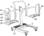
FIGS. 1 and 2 are schematic structural views of the movable lifting electric power-assisted chair provided by the utility model from different viewing angles;
FIG. 3 is a schematic cross-sectional view of a locking closure provided by the present invention;
FIG. 4 is a schematic cross-sectional view of the snap structure provided in the present invention;
fig. 5 is a schematic structural view of a seat of the booster chair according to the present invention in a deployed state.
Detailed Description
In order to make the objects, technical solutions and advantages of the present invention more apparent, the present invention will be described in further detail with reference to the accompanying drawings. It is only noted that the utility model is intended to be limited to the specific forms set forth herein, including any reference to the drawings, as well as any other specific forms of embodiments of the utility model.
As shown in fig. 1-2 and fig. 5, an embodiment of the present invention provides a movable lifting electric power-assisted chair, which includes a chassis 1, a sliding plate 2 capable of sliding on the chassis 1, a lifting structure 3 mounted on the sliding plate 2, and a support 4 connected to the lifting structure 3; two sides of the chassis 1 are provided with side plates 11 and universal wheels 12 arranged on two sides of the side plates 11, and the sliding plate 2 is connected with the chassis 1 in a sliding way through a sliding mechanism 5; the lifting structure 3 comprises an electric push rod 31, a lifting seat 32 arranged on the electric push rod 31, an electric device 33 arranged in the lifting seat 32, a lifting control rod 34 arranged on the lifting seat 32 and a bracket 4 connected with two sides of the lifting seat 32; the electric device 33 is connected with the electric push rod 31, the lifting control rod 34 is used for controlling the work of the electric device 33, the brackets 4 on the two sides are respectively hinged with the connecting rod frame 35, and the connecting rod frames 35 on the two sides are movably connected with the seat 6 through pin shafts; the seat 6 comprises two mutually closed back cushions 61 and two mutually closed seat cushions 62, wherein the seat cushions 62 are positioned at the bottom of the connecting rod frame 35, and the back cushions 61 are positioned at one side of the connecting rod frame 35; the link frame 35 is provided with a locking and closing device 63, and the two link frames 35 can be locked and closed or opened by controlling the locking and closing device 63, so that the seat cushion 62 and the back cushion 61 can be locked and closed or opened. Preferably, the electric device 33 is a driving motor.
The lifting structure 3 adopts the electric push rod 31 to ensure that the lifting stability of the whole structure is strong, and the lifting control rod 34 is used for controlling the work of the electric device 33 to control the electric push rod 31 to move up and down, so that the height of the seat 6 can be adjusted; can be suitable for sofas, beds or toilet seats with different heights; the sliding mechanism 5 can enable the sliding plate 2 and the chassis 1 to slide relatively, so that the seat 6 on the sliding plate 2 can slide horizontally on the base, and the seat 6 can be translated or approached to a sofa, a bed or a toilet seat; the seat 6 is positioned above a sofa, bed or toilet seat; the two link frames 35 can be locked and closed or opened by controlling the locking and closing device 63, so that the seat cushion 62 and the back cushion 61 can be locked and closed or opened; the chair is convenient for old people and patients with inconvenient legs and feet to move to a sofa, a bed or a toilet seat or move from the sofa, the bed or the toilet seat to the chair 6 of the power-assisted chair. And the old people and patients who have inconvenient legs and feet on the seat of the power-assisted chair can be placed on the seat 6 of the power-assisted chair to move through the universal wheels 12 on the chassis 1, and can move to other places.
Specifically, as shown in fig. 3, the locking closing device 63 includes a first closing plate 64, a second closing plate 65 and a locking switch 66, the locking switch 66 is mounted on the first closing plate 64, and the first closing plate 64 and the second closing plate 65 are respectively connected to the two side link holders 35 and also respectively connected to the back pad 61; the first closing plate 64 and the second closing plate 65 can be closed or opened relatively by rotating the locking switch 66, so that the seat cushion 62 and the back cushion 61 can be locked and closed or opened, and the old and the patient with the leg and foot inconvenience can sit on the sofa, bed or toilet seat from the seat 6.
The locking switch 66 is further provided with a locking sliding buckle 67, the locking sliding buckle 67 is arranged in the first closing plate 64, and a clamping groove 68 corresponding to the locking sliding buckle 67 is arranged in the second closing plate 65; by rotating the locking switch 66, the locking slider 67 can be engaged with or disengaged from the engaging groove 68, so that the first closing plate 64 and the second closing plate 65 can be locked, closed or opened, and the elderly and patients with leg and foot disabilities can sit on the sofa, bed or toilet seat from the seat 6. The locking switch 66 is simple in structure and easy to operate.
Preferably, the sliding mechanism 5 comprises a sliding rail shaft 51 and a shaft sleeve 52, the sliding rail shaft 51 is respectively arranged in the side plates 11 at the two sides, and the shaft sleeve 52 is respectively arranged at the two ends of the sliding plate 2; the shaft sleeve 52 is sleeved in the slide rail shaft 51, and the slide plate 2 can slide relative to the chassis 1 through the sliding connection between the slide rail shaft 51 and the shaft sleeve 52, so that the seat 6 on the slide plate 2 can slide horizontally on the base relatively, and the seat 6 can be translated or moved close to a sofa, a bed or a toilet seat; is convenient for the old and the patient with inconvenient follow-up legs and feet to move.
In order to realize the fixed connection of the sliding plate 2 and the chassis 1. As shown in fig. 4, a buckle structure 21 is arranged between the slide plate 2 and the chassis 1, the buckle structure 21 includes a pedal 22 and a buckle 23, the pedal 22 is arranged on the slide plate 2, the pedal 22 is provided with a buckle groove 24, and the buckle 23 is arranged on the chassis 1; buckle groove 24 is connected with buckle 23 block, can make slide 2 and chassis 1 fixed connection, and the inconvenient old person of leg and foot and patient of being convenient for sit on the helping hand chair or when helping hand chair itself removes, avoid slide 2 and seat 6 above that easily slide and cause and rock to improve the inconvenient old person of leg and foot and patient's on it mobility stability and security, or the mobility stability of helping hand chair, prevent to lead to the fact unnecessary collision or impaired because of sliding. By stepping on the pedal 22, the buckle groove 24 can be separated from the buckle 23, so that the sliding plate 2 can be slidably connected with the chassis 1, the sliding plate 2 can horizontally slide on the chassis 1 relatively, the seat 6 can be horizontally moved or be close to a sofa, a bed or a toilet seat, and the movement of the old and patients with the subsequent inconvenience in legs and feet is facilitated.
In order to prevent the old with inconvenient legs and feet and the patients from worrying about the flustered feet. As shown in fig. 5, pedals 37 are arranged on two sides of the electric push rod 31, and the pedals 37 synchronously ascend and descend along with the ascending and descending movement of the electric push rod 31, so that the feet of the old and the patients with inconvenient legs and feet can stably step on the pedals 37, thereby preventing the feet of the users from being empty and causing worry, and improving the use stability and the safety of the power-assisted chair.
In order to facilitate the old people and patients with inconvenient legs and feet to go to the toilet. The two seat cushions 62 that are closed to each other are provided with openings on their inner sides, and when the two seat cushions 62 are closed to each other, the openings form a through hole 621. When the chair 6 of the power-assisted chair is positioned on a toilet seat, the old people and patients with inconvenient legs and feet can conveniently go to the toilet through the through hole 621 directly.
Preferably, the lower end surfaces of the two seat cushions 62 that are closed to each other are provided with sliding grooves 622, and when the two seat cushions 62 are closed to each other, the sliding grooves 622 are used for slidably connecting with the toilet bowl 7, so that the toilet bowl 7 can be located below the through hole 621. Old people and patients with inconvenient legs and feet on the power-assisted chair can directly go to the toilet through the bedpan 7 under the condition that the old people and the patients are inconvenient to move to the toilet.
Preferably, handles 8 are arranged on two sides of the bedpan 7, so that a user can move and place the bedpan 7 conveniently.
Preferably, the lifting seat 32 is provided with a circular charging hole 9, and the circular charging hole 9 is used for charging a charging power supply of the electric device 33, so as to ensure the continuous operation of the electric device 33.
The above disclosure is only for the purpose of illustrating the preferred embodiments of the present invention and is not to be construed as limiting the scope of the present invention, therefore, the present invention is not limited by the appended claims.
Claims (10)
1. The electric power-assisted chair capable of moving up and down is characterized by comprising a chassis, a sliding plate capable of sliding on the chassis, a lifting structure arranged on the sliding plate and a bracket connected with the lifting structure;
the two sides of the chassis are provided with side plates and universal wheels arranged on the two sides of the side plates, and the sliding plate is connected with the chassis in a sliding manner through a sliding mechanism;
the lifting structure comprises an electric push rod, a lifting seat arranged on the electric push rod, an electric device arranged in the lifting seat, a lifting control rod arranged on the lifting seat and the bracket connected with the two sides of the lifting seat;
the electric device is connected with the electric push rod, the lifting control rod is used for controlling the electric device to work, the supports on two sides are respectively hinged with the connecting rod frame, and the connecting rod frames on two sides are connected with seats;
the seat comprises two back cushions and two seat cushions, wherein the back cushions are closed mutually, the seat cushions are positioned at the bottom of the connecting rod frame, and the back cushions are positioned on one side of the connecting rod frame;
the connecting rod frames are provided with locking and closing devices, and the two connecting rod frames can be locked, closed or opened by controlling the locking and closing devices, so that the seat cushion and the back cushion can be locked, closed or opened.
2. The movable lifting electric power-assisted chair according to claim 1, wherein the sliding mechanism comprises a sliding rail shaft and shaft sleeves, the sliding rail shaft is respectively arranged in the side plates at two sides, and the shaft sleeves are respectively arranged at two ends of the sliding plate;
the shaft sleeve is sleeved in the sliding rail shaft, and the sliding plate can slide relative to the chassis through the sliding connection between the sliding rail shaft and the shaft sleeve.
3. The movable lifting electric power-assisted chair according to claim 1, wherein the locking closing device comprises a first closing plate, a second closing plate and a locking switch, the locking switch is installed on the first closing plate, the first closing plate and the second closing plate are respectively connected with the two side connecting rod frames and the back cushion;
the first closing plate and the second closing plate can be closed or opened relatively by rotating the locking switch.
4. The movable lifting electric power-assisted chair according to claim 3, wherein the locking switch is further provided with a locking slider which is arranged in the first closing plate, and a clamping groove corresponding to the locking slider is arranged in the second closing plate;
through rotating the locking switch, the locking slider can be connected with or separated from the clamping groove in a clamping manner, so that the first closing plate and the second closing plate are locked, closed or opened.
5. The movable lifting electric power-assisted chair according to claim 1 or 2, characterized in that a buckle structure is arranged between the sliding plate and the chassis, and the buckle structure can fixedly connect the sliding plate and the chassis.
6. The electrically assisted and liftable chair according to claim 5, wherein the buckle structure comprises a pedal and a buckle, the pedal is disposed on the slide plate, the pedal is provided with a buckle groove, and the buckle is mounted on the chassis;
the buckle groove is connected with the buckle in a clamping mode, the sliding plate can be fixedly connected with the chassis, the buckle groove can be separated from the buckle by stepping on the pedal, and therefore the sliding plate can be connected with the chassis in a sliding mode.
7. The movable lifting electric power-assisted chair according to claim 1, characterized in that pedals are arranged on two sides of the electric push rod.
8. The portable, liftable, electrically powered booster seat as claimed in claim 1, wherein the openings are formed in the two closed seat cushions, and a through opening is formed in the two openings when the two seat cushions are closed.
9. A movable lifting electric power-assisted chair according to claim 1, characterized in that the lower end surfaces of the two seat cushions which are closed with each other are provided with sliding grooves which are used for being connected with a bedpan in a sliding way when the two seat cushions are closed with each other.
10. A movable liftable electrically-assisted chair according to claim 9, wherein handles are provided on both sides of the bedpan.
Priority Applications (1)
| Application Number | Priority Date | Filing Date | Title |
|---|---|---|---|
| CN202122548030.4U CN216294469U (en) | 2021-10-22 | 2021-10-22 | Electric power-assisted chair capable of moving and lifting |
Applications Claiming Priority (1)
| Application Number | Priority Date | Filing Date | Title |
|---|---|---|---|
| CN202122548030.4U CN216294469U (en) | 2021-10-22 | 2021-10-22 | Electric power-assisted chair capable of moving and lifting |
Publications (1)
| Publication Number | Publication Date |
|---|---|
| CN216294469U true CN216294469U (en) | 2022-04-15 |
Family
ID=81116862
Family Applications (1)
| Application Number | Title | Priority Date | Filing Date |
|---|---|---|---|
| CN202122548030.4U Active CN216294469U (en) | 2021-10-22 | 2021-10-22 | Electric power-assisted chair capable of moving and lifting |
Country Status (1)
| Country | Link |
|---|---|
| CN (1) | CN216294469U (en) |
-
2021
- 2021-10-22 CN CN202122548030.4U patent/CN216294469U/en active Active
Similar Documents
| Publication | Publication Date | Title |
|---|---|---|
| RU2767548C1 (en) | Multifunctional wheelchair | |
| JP2748227B2 (en) | Electric wheelchair | |
| CN110037870B (en) | Combined medical nursing bed | |
| CN112603685B (en) | Multifunctional nursing bed, matched bed and chair combination device and use method | |
| TWI693933B (en) | Multifunctional wheelchair | |
| CN109350408B (en) | Nursing chair for bed passing | |
| KR102423485B1 (en) | Auto lifting-moving chair apparatus for parapiegic capable of lifting and moving | |
| JP6302769B2 (en) | Seating assistance device | |
| CN110876662A (en) | Wheelchair convenient to get up and using method | |
| CN214967884U (en) | Wheelchair for medical care | |
| KR20130098508A (en) | A moving method for a patient paralyzed from the waist down | |
| CN216294469U (en) | Electric power-assisted chair capable of moving and lifting | |
| CN210185891U (en) | Nursing bed | |
| CN113995592B (en) | Bed-chair integrated robot with semi-automatic separation and butt joint functions | |
| CN217489147U (en) | Supplementary device that seamless formula of half disability old person got off bed and carries out indoor activity | |
| CN215385450U (en) | Shifting machine | |
| CN216676145U (en) | Wheelchair bed | |
| JPH08196573A (en) | Nursing care mobile device | |
| CN210144935U (en) | Bed-chair separated nursing bed wheelchair | |
| CN212090063U (en) | Holding type side shifting vehicle with bed and chair functions | |
| CN210903717U (en) | Multifunctional wheelchair assisting getting on and off bed | |
| CN211095494U (en) | Medical bed turnover device | |
| CN110711087A (en) | Dual-purpose wheelchair of disconnect-type seat | |
| CN215459612U (en) | Simple sitting-in type displacement vehicle with lifting function for disabled people | |
| CN111358627A (en) | Holding type side shifting vehicle with bed and chair functions |
Legal Events
| Date | Code | Title | Description |
|---|---|---|---|
| GR01 | Patent grant | ||
| GR01 | Patent grant |