Industrial automation line convenient to overhaul
Technical Field
The utility model relates to the technical field of industrial automatic production lines, in particular to an industrial automatic production line convenient to overhaul.
Background
The automatic production line is a production organization form for realizing the product process by an automatic machine system, the phenomenon that the existing industrial automatic small-sized production line is likely to be damaged in use can occur, sometimes the existing industrial automatic small-sized production line needs to be moved to a specified position for maintenance, but most of the existing industrial automatic small-sized production lines have the problem of inconvenient movement, if the existing industrial automatic small-sized production lines need to be convenient to move, pulleys are usually installed at the bottom of the device and move by virtue of the pulleys, but because only the pulleys are in contact with the ground for supporting, the stability of the industrial automatic small-sized production line in operation can be reduced, the displacement is easy to generate, and if the supporting legs are used for supporting, the device is inconvenient to move, the practicability of the industrial automatic small-sized production line is reduced, and the maintenance of the industrial automatic small-sized production line is not facilitated.
SUMMERY OF THE UTILITY MODEL
The utility model aims to provide an industrial automatic production line convenient to overhaul, which has the advantage of high practicability and solves the problem of lower practicability of the existing industrial automatic production line.
In order to achieve the purpose, the utility model provides the following technical scheme: an industrial automatic production line convenient to overhaul comprises a production line body, wherein the bottom of the production line body is fixedly connected with a base, the bottom of the base is fixedly connected with supporting legs, two sides of the base are fixedly connected with limit boxes, the inner cavity of each limit box is provided with a limit plate, one side of each limit plate opposite to the corresponding limit plate is fixedly connected with a first spring, one side of each limit plate opposite to the corresponding limit plate is fixedly connected with a stop dog, one side of each stop dog opposite to the corresponding limit plate penetrates through the inner cavity of the base, the inner cavity of the base and the bottom of the two stop dogs are provided with lifting plates, the bottom of each lifting plate is fixedly connected with a movable wheel, the bottom of each movable wheel penetrates through the bottom of the base, the tops of two sides of the back of the base are fixedly connected with motors, the front side of the output end of each motor penetrates through the inner cavity of the base and is fixedly connected with a rotating disc, and the positive surface of the rotating disc is fixedly connected with a rotating block, the surface cover of rotatory piece is equipped with the removal shell, two equal fixedly connected with ejector pads in the opposite one side of removal shell, the bottom fixedly connected with pinch roller of removal shell, the top fixedly connected with of lifter plate and the stopper that the pinch roller cooperation was used.
Preferably, the number of the moving wheels and the number of the supporting legs are four, and the surface of the rotating block is in sliding connection with the inner wall of the moving shell.
Preferably, the shape of the limiting block is trapezoidal, and the bottom of the pressing wheel is in contact with the limiting block.
Preferably, the bottom fixedly connected with gag lever post of base inner chamber, the surface cover of gag lever post is equipped with the second spring, the top of gag lever post runs through to the top and the fixedly connected with baffle of lifter plate, the spacing hole of using with the gag lever post cooperation is seted up at the top of lifter plate.
Preferably, the top of the inner cavity of the base is fixedly connected with a fixed box between the two movable shells, the two sides of the inner cavity of the fixed box are respectively provided with a movable block, the top and the bottom of the opposite sides of the two movable blocks are respectively fixedly connected with a movable rod, and one end of the movable rod, which is far away from the movable blocks, penetrates through the fixed box and is fixedly connected with the movable shells.
Preferably, the top of the movable shell is fixedly connected with a sliding block, the top of the inner cavity of the base is provided with a sliding groove, and the top of the sliding block extends to the inner cavity of the sliding groove.
Compared with the prior art, the utility model has the following beneficial effects:
1. according to the utility model, the problem of low practicability of the existing industrial automatic production line is solved by arranging the production line body, the base, the supporting legs, the limiting box, the limiting plate, the first spring, the stop block, the lifting plate, the moving wheel, the motor, the rotary disk, the rotary block, the moving shell, the push block, the pinch roller and the limiting block, and the industrial automatic production line has the advantage of high practicability.
2. The lifting plate moving device can be used for supporting the lifting plate by arranging the moving wheels, can be used for pushing the stop block by arranging the stop block, can improve the moving stability of the lifting plate by arranging the limiting rod, can limit the moving range of the lifting plate by arranging the baffle plate, can improve the moving stability of the moving shell by arranging the fixed box, the moving block and the moving rod, and can further improve the moving stability of the moving shell by arranging the sliding block and the sliding groove.
Drawings
FIG. 1 is a schematic structural view of the present invention;
FIG. 2 is a front view of the structure of the present invention;
fig. 3 is a right partial cross-sectional view of the base of the present invention.
In the figure: 1. a production line body; 2. a base; 3. supporting legs; 4. a limiting box; 5. a limiting plate; 6. a first spring; 7. a stopper; 8. a lifting plate; 9. a moving wheel; 10. a motor; 11. rotating the disc; 12. rotating the block; 13. moving the shell; 14. a push block; 15. a pinch roller; 16. a limiting block; 17. a limiting rod; 18. a second spring; 19. a baffle plate; 20. a fixing box; 21. a moving block; 22. the rod is moved.
Detailed Description
The technical solutions in the embodiments of the present invention will be clearly and completely described below with reference to the drawings in the embodiments of the present invention, and it is obvious that the described embodiments are only a part of the embodiments of the present invention, and not all of the embodiments. All other embodiments, which can be derived by a person skilled in the art from the embodiments given herein without making any creative effort, shall fall within the protection scope of the present invention.
In the description of the present invention, it should be noted that the terms "upper", "lower", "inner", "outer", "front", "rear", "both ends", "one end", "the other end", and the like indicate orientations or positional relationships based on the orientations or positional relationships shown in the drawings, and are only for convenience of describing the present invention and simplifying the description, but do not indicate or imply that the referred device or element must have a specific orientation, be constructed in a specific orientation, and be operated, and thus, should not be construed as limiting the present invention. Furthermore, the terms "first" and "second" are used for descriptive purposes only and are not to be construed as indicating or implying relative importance.
In the description of the present invention, it is to be noted that, unless otherwise explicitly specified or limited, the terms "mounted", "provided", "connected", and the like are to be construed broadly, such as "connected", which may be fixedly connected, detachably connected, or integrally connected; can be mechanically or electrically connected; they may be connected directly or indirectly through intervening media, or they may be interconnected between two elements. The specific meanings of the above terms in the present invention can be understood in specific cases to those skilled in the art.
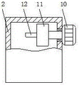
Referring to fig. 1-3, an industrial automatic production line convenient for maintenance comprises a production line body 1, a base 2 is fixedly connected to the bottom of the production line body 1, support legs 3 are fixedly connected to the bottom of the base 2, limit boxes 4 are fixedly connected to both sides of the base 2, limit plates 5 are arranged in inner cavities of the limit boxes 4, first springs 6 are fixedly connected to opposite sides of the two limit plates 5, stop blocks 7 are fixedly connected to opposite sides of the two limit plates 5, opposite sides of the two stop blocks 7 are respectively penetrated to the inner cavities of the base 2, a lifting plate 8 is arranged in the inner cavity of the base 2 and positioned at the bottoms of the two stop blocks 7, a moving wheel 9 is fixedly connected to the bottom of the lifting plate 8, the bottom of the moving wheel 9 is penetrated to the bottom of the base 2, motors 10 are fixedly connected to the tops of both sides of the back of the base 2, the front sides of output ends of the motors 10 are penetrated to the inner cavities of the base 2 and fixedly connected with rotating disks 11, the front surface of the rotating disk 11 is fixedly connected with a rotating block 12, the surface of the rotating block 12 is sleeved with a moving shell 13, one opposite side of each of the two moving shells 13 is fixedly connected with a push block 14, the bottom of the moving shell 13 is fixedly connected with a pinch roller 15, the top of the lifting plate 8 is fixedly connected with a limit block 16 matched with the pinch roller 15 for use, the number of the moving wheels 9 and the number of the supporting legs 3 are four, the surface of the rotating block 12 is slidably connected with the inner wall of the moving shell 13, the shape of the limit block 16 is trapezoidal, the bottom of the pinch roller 15 is contacted with the limit block 16, the bottom of the inner cavity of the base 2 is fixedly connected with a limit rod 17, the surface of the limit rod 17 is sleeved with a second spring 18, the top of the limit rod 17 penetrates through the top of the lifting plate 8 and is fixedly connected with a baffle 19, the top of the lifting plate 8 is provided with a limit hole matched with the limit rod 17 for use, the top of the inner cavity of the base 2 is fixedly connected with a fixing box 20 positioned between the two moving shells 13, the two sides of the inner cavity of the fixed box 20 are respectively provided with a movable block 21, the top and the bottom of the opposite sides of the two movable blocks 21 are respectively and fixedly connected with a movable rod 22, one end of the movable rod 22, far away from the movable blocks 21, penetrates through the fixed box 20 and is fixedly connected with the movable shell 13, the top of the movable shell 13 is fixedly connected with a slide block, the top of the inner cavity of the base 2 is provided with a slide groove, the top of the slide block extends to the inner cavity of the slide groove, the movement of the whole device can be facilitated by arranging a movable wheel 9, the lifting plate 8 can be supported by arranging a stop 7, the pushing block 14 can be used for pushing the stop 7, the stability of the movement of the lifting plate 8 can be improved by arranging a limiting rod 17, the movement range of the lifting plate 8 can be limited by arranging a baffle 19, the stability of the movement of the movable shell 13 can be improved by arranging the fixed box 20, the movable blocks 21 and the movable rods 22, through setting up slider and spout, can further improve the stability that removes shell 13 and remove, through setting up production line body 1, base 2, supporting leg 3, spacing box 4, limiting plate 5, first spring 6, dog 7, lifter plate 8, remove wheel 9, motor 10, rotary disk 11, rotatory piece 12, remove shell 13, ejector pad 14, pinch roller 15 and stopper 16, the lower problem of current industrial automation line practicality has been solved, this industrial automation line possesses the advantage that the practicality is high.
When the device is used, a user controls the motor 10 to run and drives the rotating block 12 to rotate through the cooperation of the rotating disc 11, the rotating block 12 rotates and drives the two moving shells 13 to move towards the middle, the moving shells 13 drive the two pressing wheels 15 to move towards the middle to extrude the limiting block 16, so that the limiting block 16 moves downwards, the limiting block 16 drives the lifting plate 8 and the moving wheel 9 to move downwards until the bottom of the moving wheel 9 is positioned below the supporting leg 3, the lifting plate 8 is positioned below the stop block 7, the first spring 6 resets and drives the two stop blocks 7 to move towards the middle to the top of the lifting plate 8 through the cooperation of the limiting plate 5, the lifting plate 8 is fixed, the lifting plate 8 is prevented from moving upwards, the whole device can be moved through the cooperation of the moving wheel 9 at the moment, after the device is moved to a required position, the motor 10 is controlled to run and drive the rotating block 12 to rotate through the cooperation of the rotating disc 11, and the rotating block 12 drives the two moving shells 13 to move away from each other, the movable shell 13 drives the push block 14 to extrude the stop blocks 7, so that the two stop blocks 7 move to the opposite side, the limit of the stop blocks 7 on the lifting plate 8 is removed, at the moment, the base 2 and the supporting legs 3 can move downwards due to the action of gravity until the bottoms of the supporting legs 3 are in contact with the ground, the stability of the whole device can be improved, and the device is prevented from generating displacement.
Although embodiments of the present invention have been shown and described, it will be appreciated by those skilled in the art that changes, modifications, substitutions and alterations can be made in these embodiments without departing from the principles and spirit of the utility model, the scope of which is defined in the appended claims and their equivalents.