CN216216696U - Flat roof is with light-duty photovoltaic support - Google Patents
Flat roof is with light-duty photovoltaic support Download PDFInfo
- Publication number
- CN216216696U CN216216696U CN202122903347.5U CN202122903347U CN216216696U CN 216216696 U CN216216696 U CN 216216696U CN 202122903347 U CN202122903347 U CN 202122903347U CN 216216696 U CN216216696 U CN 216216696U
- Authority
- CN
- China
- Prior art keywords
- photovoltaic support
- bolt
- mounting
- mounting panel
- mounting bracket
- Prior art date
- Legal status (The legal status is an assumption and is not a legal conclusion. Google has not performed a legal analysis and makes no representation as to the accuracy of the status listed.)
- Active
Links
Images
Classifications
-
- Y—GENERAL TAGGING OF NEW TECHNOLOGICAL DEVELOPMENTS; GENERAL TAGGING OF CROSS-SECTIONAL TECHNOLOGIES SPANNING OVER SEVERAL SECTIONS OF THE IPC; TECHNICAL SUBJECTS COVERED BY FORMER USPC CROSS-REFERENCE ART COLLECTIONS [XRACs] AND DIGESTS
- Y02—TECHNOLOGIES OR APPLICATIONS FOR MITIGATION OR ADAPTATION AGAINST CLIMATE CHANGE
- Y02B—CLIMATE CHANGE MITIGATION TECHNOLOGIES RELATED TO BUILDINGS, e.g. HOUSING, HOUSE APPLIANCES OR RELATED END-USER APPLICATIONS
- Y02B10/00—Integration of renewable energy sources in buildings
- Y02B10/10—Photovoltaic [PV]
-
- Y—GENERAL TAGGING OF NEW TECHNOLOGICAL DEVELOPMENTS; GENERAL TAGGING OF CROSS-SECTIONAL TECHNOLOGIES SPANNING OVER SEVERAL SECTIONS OF THE IPC; TECHNICAL SUBJECTS COVERED BY FORMER USPC CROSS-REFERENCE ART COLLECTIONS [XRACs] AND DIGESTS
- Y02—TECHNOLOGIES OR APPLICATIONS FOR MITIGATION OR ADAPTATION AGAINST CLIMATE CHANGE
- Y02E—REDUCTION OF GREENHOUSE GAS [GHG] EMISSIONS, RELATED TO ENERGY GENERATION, TRANSMISSION OR DISTRIBUTION
- Y02E10/00—Energy generation through renewable energy sources
- Y02E10/50—Photovoltaic [PV] energy
Abstract
The utility model discloses a light photovoltaic support for a flat roof, and belongs to the technical field of photovoltaic modules. The utility model provides a flat roof is with light-duty photovoltaic support, includes the mounting panel, the mounting panel left and right sides all is equipped with two guide arms, two adjacent guide arm middle parts are rotated and are connected with the aviation baffle, the mounting panel upper end is equipped with two and rotates the seat, rotates the seat front end and is equipped with bolt A, two rotate the seat middle parts and be equipped with the mounting bracket, both ends are symmetrical structure around the mounting bracket inner wall and have seted up two spouts, the inside a plurality of sliders that are equipped with of spout, the slider upper end is equipped with bolt B, the mounting bracket middle part is equipped with a plurality of fly leafs. According to the photovoltaic support, the direction of wind can be changed through the air guide plate, so that the resistance generated by the device is reduced, the device is more stable, the photovoltaic support body is protected, and the damage to the back of the solar panel caused by overlarge wind force due to overlarge wind force can be avoided.
Description
Technical Field
The utility model relates to the technical field of photovoltaic modules, in particular to a light photovoltaic support for a flat roof.
Background
Along with the development of society, solar energy utilization is more and more extensive, wherein often can utilize the photovoltaic support to install solar panel on flat roof for better absorption solar energy, wherein, because the roof height is higher, shelter from the thing less around, solar panel slope can produce great resistance when wind-force is great, and then leads to the photovoltaic support to damage, or makes solar panel damage, and the photovoltaic support is fixed the important subassembly on the roof as solar panel, and traditional photovoltaic support is difficult to protect solar panel and self in the use, and the practicality is relatively poor. In view of this, we propose a lightweight photovoltaic support for flat roofs.
SUMMERY OF THE UTILITY MODEL
1. Technical problem to be solved
The utility model aims to provide a light photovoltaic bracket for a flat roof, which solves the problems in the prior art.
2. Technical scheme
The utility model provides a flat roof is with light-duty photovoltaic support, includes the mounting panel, the mounting panel left and right sides all is equipped with two guide arms, two adjacent guide arm middle parts are rotated and are connected with the aviation baffle, the mounting panel upper end is equipped with two and rotates the seat, it is equipped with bolt A to rotate the seat front end, and two rotate the seat middle parts and be equipped with the mounting bracket, both ends are symmetrical structure around the mounting bracket inner wall and have seted up two spouts, the inside a plurality of sliders that are equipped with of spout, the slider upper end is equipped with bolt B, the mounting bracket middle part is equipped with a plurality of fly leafs.
Preferably, the outer wall of the guide rod is in sliding contact with the inside of the mounting plate, and the tail end of the air deflector is rotatably connected with the lower end of the mounting frame.
Preferably, the end of the bolt a is in pressing contact with the front end of the mounting bracket.
Preferably, the sliding block is in sliding connection with the sliding groove, the bolt B is in threaded connection with the sliding block, and the tail end of the bolt B is in pressing contact with the inner wall of the sliding groove.
Preferably, the movable plate is of an I-shaped structure, and the front end and the rear end of the movable plate are fixedly connected with one ends of the two opposite sliding blocks respectively.
3. Advantageous effects
Compared with the prior art, the utility model has the advantages that:
1. according to the photovoltaic support, the direction of wind can be changed through the air guide plate, so that the resistance generated by the device is reduced, the device is more stable, the photovoltaic support body is protected, and the damage to the back of the solar panel caused by overlarge wind force due to overlarge wind force can be avoided.
2. The installation frame can rotate, so that the solar panel can face the sun, the movable plate with the I-shaped structure can be used for fixing the solar panel conveniently, the movable plate can slide along the direction of the sliding groove through the arranged sliding block, the device can be suitable for solar panels with different sizes, and the practicability of the device is improved.
Drawings
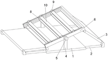
FIG. 1 is a schematic view of the overall structure of the present invention;
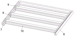
FIG. 2 is a schematic view of a portion of the mount of the present invention;
the reference numbers in the figures illustrate: 1. mounting a plate; 2. a guide bar; 3. an air deflector; 4. a rotating seat; 5. a bolt A; 6. a mounting frame; 7. a chute; 8. a slider; 9. a bolt B; 10. a movable plate.
Detailed Description
Referring to fig. 1-2, the present invention provides a technical solution:
the utility model provides a flat roof is with light-duty photovoltaic support, including mounting panel 1, the 1 left and right sides of mounting panel all is equipped with two guide arms 2, two adjacent guide arms 2 middle parts are rotated and are connected with aviation baffle 3, 1 upper end of mounting panel is equipped with two and rotates seat 4, it is equipped with bolt A5 to rotate 4 front ends of seat, two are rotated 4 middle parts of seat and are equipped with mounting bracket 6, both ends are symmetrical structure around the 6 inner walls of mounting bracket and have seted up two spout 7, spout 7 inside is equipped with a plurality of sliders 8, 8 upper ends of slider are equipped with bolt B9, 6 middle parts of mounting bracket are equipped with a plurality of fly leaves 10.
Specifically, the outer wall of the guide rod 2 is in sliding contact with the inside of the mounting plate 1, and the tail end of the air deflector 3 is rotatably connected with the lower end of the mounting frame 6. The guide rod 2 can drive the air deflector 3 to rotate after the mounting rack 6 rotates.
Further, the end of the bolt a5 is in pressing contact with the front end of the mounting bracket 6. The mounting frame 6 can be fixed by the provided bolt a 5.
Still further, slider 8 and spout 7 sliding connection, bolt B9 and slider 8 threaded connection, bolt B9 terminal and spout 7 inner wall extrusion contact. The movable plate 10 can slide along the direction of the sliding chute 7 through the slide block 8 and the sliding chute 7.
Furthermore, the movable plate 10 is in an i-shaped structure, and the front end and the rear end of the movable plate 10 are respectively fixedly connected with one end of the two opposite sliding blocks 8. The movable plate 10 of the I-shaped structure can facilitate fixing the solar panel.
The working principle is as follows: when wind power is large, the wind blows the device and then under the action of the air deflector 3, the direction of the wind can be changed, so that the resistance generated by the device is reduced, the device is more stable, the mounting frame 6 can be rotated through the loose bolt A5, the solar panel on the mounting frame 6 can face the sun, the effect of absorbing the sun is better, the position of each slider 8 can be adjusted through the loose bolt B9, the slider 8 slides along the direction of the sliding groove 7, the movable plate 10 is moved, a worker can take down the damaged solar panel after the movable plate 10 is moved, the damaged solar panel is aligned and replaced, the device can be suitable for solar panels of different sizes by moving the movable plate 10, and the practicability of the device is further improved.
Claims (5)
1. The utility model provides a flat roof is with light-duty photovoltaic support, includes mounting panel (1), its characterized in that: the utility model discloses a mounting panel, including mounting panel (1), mounting panel, rotation seat (4), bolt A (5), mounting panel (6), spout (7) are set up to the both ends and are symmetrical structure around mounting panel (1) upper end, rotation seat (4) front end is equipped with bolt A (5), and two rotation seat (4) middle parts are equipped with mounting bracket (6), mounting bracket (6) inner wall both ends are equipped with two spouts (7), spout (7) inside is equipped with a plurality of sliders (8), slider (8) upper end is equipped with bolt B (9), mounting bracket (6) middle part is equipped with a plurality of fly leafs (10).
2. A lightweight photovoltaic support for flat roofs according to claim 1 wherein: the outer wall of the guide rod (2) is in sliding contact with the inside of the mounting plate (1), and the tail end of the air deflector (3) is rotatably connected with the lower end of the mounting frame (6).
3. A lightweight photovoltaic support for flat roofs according to claim 1 wherein: the tail end of the bolt A (5) is in pressing contact with the front end of the mounting frame (6).
4. A lightweight photovoltaic support for flat roofs according to claim 1 wherein: slider (8) and spout (7) sliding connection, bolt B (9) and slider (8) threaded connection, bolt B (9) end and spout (7) inner wall extrusion contact.
5. A lightweight photovoltaic support for flat roofs according to claim 1 wherein: the movable plate (10) is of an I-shaped structure, and the front end and the rear end of the movable plate (10) are fixedly connected with one ends of two opposite sliding blocks (8) respectively.
Priority Applications (1)
| Application Number | Priority Date | Filing Date | Title |
|---|---|---|---|
| CN202122903347.5U CN216216696U (en) | 2021-11-24 | 2021-11-24 | Flat roof is with light-duty photovoltaic support |
Applications Claiming Priority (1)
| Application Number | Priority Date | Filing Date | Title |
|---|---|---|---|
| CN202122903347.5U CN216216696U (en) | 2021-11-24 | 2021-11-24 | Flat roof is with light-duty photovoltaic support |
Publications (1)
| Publication Number | Publication Date |
|---|---|
| CN216216696U true CN216216696U (en) | 2022-04-05 |
Family
ID=80914505
Family Applications (1)
| Application Number | Title | Priority Date | Filing Date |
|---|---|---|---|
| CN202122903347.5U Active CN216216696U (en) | 2021-11-24 | 2021-11-24 | Flat roof is with light-duty photovoltaic support |
Country Status (1)
| Country | Link |
|---|---|
| CN (1) | CN216216696U (en) |
-
2021
- 2021-11-24 CN CN202122903347.5U patent/CN216216696U/en active Active
Similar Documents
| Publication | Publication Date | Title |
|---|---|---|
| CN212210912U (en) | Solar photovoltaic panel sun facing adjusting mechanism | |
| CN204928729U (en) | Novel solar photovoltaic board self -cleaning device | |
| CN202307940U (en) | Folding solar cell square matrix | |
| CN208723852U (en) | A kind of convertible solar photovoltaic assembly of automatically cleaning | |
| CN214840516U (en) | Solar street lamp structure based on new forms of energy | |
| CN216216696U (en) | Flat roof is with light-duty photovoltaic support | |
| CN109617516B (en) | Solar photovoltaic power generation device capable of being adjusted at multiple angles | |
| CN206884949U (en) | A kind of automobile-used solar charging device | |
| CN204928728U (en) | Two motor drive solar photovoltaic board self -cleaning devices | |
| CN210297604U (en) | Foldable solar photovoltaic power generation mounting rack | |
| CN210718138U (en) | Mounting structure of solar heat collection plate | |
| CN113251374A (en) | Intelligent environment-friendly street lamp | |
| CN208723850U (en) | A kind of adjustable solar photovoltaic assembly | |
| CN220964788U (en) | Protective solar cell module | |
| CN218387376U (en) | Photovoltaic power generation board mounting bracket | |
| CN219918825U (en) | Solar panel with sun tracking system | |
| CN204906302U (en) | Improved generation solar photovoltaic board self -cleaning device | |
| CN217335503U (en) | Adjustable supporting structure of photovoltaic solar panel | |
| CN220022689U (en) | Windproof stable solar photovoltaic power generation equipment | |
| CN216851858U (en) | Photovoltaic power generation aluminum product type support | |
| CN218715410U (en) | Outer facade of old building reforms transform structure | |
| CN214014162U (en) | Safety support | |
| CN217741613U (en) | Photovoltaic module connecting device with detect function | |
| CN113585833B (en) | Install in openable and closable weather enclosure at box-type substation top | |
| CN213783234U (en) | Photovoltaic module light condensing device |
Legal Events
| Date | Code | Title | Description |
|---|---|---|---|
| GR01 | Patent grant | ||
| GR01 | Patent grant |