CN216204733U - Non-woven fabric dewatering device - Google Patents
Non-woven fabric dewatering device Download PDFInfo
- Publication number
- CN216204733U CN216204733U CN202122534286.XU CN202122534286U CN216204733U CN 216204733 U CN216204733 U CN 216204733U CN 202122534286 U CN202122534286 U CN 202122534286U CN 216204733 U CN216204733 U CN 216204733U
- Authority
- CN
- China
- Prior art keywords
- arc
- shaped frame
- frame
- guide
- barrel
- Prior art date
- Legal status (The legal status is an assumption and is not a legal conclusion. Google has not performed a legal analysis and makes no representation as to the accuracy of the status listed.)
- Active
Links
Images


Abstract
The utility model discloses a non-woven fabric dehydration device, which relates to the technical field of non-woven fabric production and comprises a cylinder body, wherein the bottom of the cylinder body is provided with a motor, the output end of the motor penetrates through the cylinder body and is fixedly connected with a rotating shaft, and the output end of the motor is rotatably connected with the bottom of the cylinder body. The non-woven fabric dewatering device is reasonable in design structure, the electro-hydraulic push rod can be operated to gradually push the first arc-shaped frame to move, so that the first arc-shaped frame moves to drive the two connecting plates on the first arc-shaped frame to respectively push the two first guide plates to move, the two connecting plates on the second arc-shaped frame are pulled together to move under the sliding of the two first guide plates, the second arc-shaped frame is pulled to approach the winding rollers, the first arc-shaped frame and the second arc-shaped frame are enabled to approach the winding rollers synchronously, the non-woven fabrics can roll on each rotary drum while being extruded, the non-woven fabric dewatering efficiency is improved, and the non-woven fabrics are dewatered more fully.
Description
Technical Field
The utility model relates to the technical field of non-woven fabric production, in particular to a non-woven fabric dehydration device.
Background
The non-woven fabric is a non-woven fabric which is formed by directly using high polymer slices, short fibers or filaments to form a net through air flow or machinery, then carrying out spunlace, needling or hot rolling reinforcement, and finally carrying out after-treatment, however, the non-woven fabric prepared by a wet method needs to be dehydrated by a dehydrating device.
The existing non-woven fabrics usually only depend on centrifugal force to throw away moisture when dehydrating for dehydration efficiency is lower, dehydration is not sufficient, and the non-woven fabrics after dehydration are easy to wrinkle into a group, and then subsequent processing difficulty is increased, and then dehydration efficiency of the non-woven fabrics is reduced. Therefore, the non-woven fabric dewatering device solves the problems.
SUMMERY OF THE UTILITY MODEL
One) technical problem to be solved
The utility model aims to make up the defects of the prior art and provides a non-woven fabric dehydration device.
II) technical scheme
In order to achieve the purpose, the utility model provides the following technical scheme: the utility model provides a non-woven fabrics dewatering device, includes the barrel, and the motor is installed to the bottom of barrel, and the output of motor runs through barrel and fixedly connected with pivot, and the output of motor rotates with the bottom of barrel to be connected, and the surface cover of pivot is equipped with the winding roller, and winding roller and pivot looks joint, and the inside of barrel is provided with extrusion mechanism and stoving mechanism.
Furthermore, the inner bottom wall of the barrel is in a boss shape, and the drain pipe is communicated with the bottom of the barrel.
Further, extrusion mechanism includes the electricity liquid push rod, first arc frame and second arc frame, electricity liquid push rod installs in the surface of barrel, and electricity liquid push rod's flexible end runs through the barrel and extends to the inside of barrel, first arc frame fixed connection is in electricity liquid push rod's flexible end, first arc frame and second arc frame are located the front and back both sides of winding roller respectively, the inner wall of first arc frame and second arc frame all rotates and is connected with the rotary drum that the equidistance was arranged, the through-hole that the equidistance was arranged is all seted up to the surface of first arc frame and second arc frame, the surface of second arc frame is provided with guiding mechanism.
Further, extrusion mechanism still includes two first guide frames, the surface of first arc frame and second arc frame all articulates there are two symmetrical connecting plates, the equal fixed connection of every first guide frame in the inner wall of barrel, two first guide frame are symmetrical each other, and two first guide frames are located the left and right sides of winding roller respectively, the equal sliding connection of inner wall of every first guide frame has first deflector, the front and the back of every first deflector all inlay and have first ball, and the inner wall sliding connection of first ball and first guide frame, two connecting plates on first arc frame and the second arc frame are equallyd divide and are do not articulated mutually with two first deflectors.
Further, guiding mechanism includes the pull rod, second deflector and second guide frame, second guide frame fixed connection is in the inner wall of barrel, and the second guide frame is located the back of second arc frame, second deflector sliding connection is in the inner wall of second guide frame, the one end fixed connection of pull rod is in the front of second deflector, the other end of pull rod is connected with the back of second arc frame, the left and right sides face of second deflector all inlays and has the second ball, and the inner wall sliding connection of second ball and second guide frame.
Further, stoving mechanism includes communicating pipe of air-supply line, circular pipe and circumference array, circular pipe fixed connection in the inner wall of barrel, the one end of air-supply line run through the barrel and with the fixed intercommunication of circular pipe, every communicating pipe all fixed intercommunication in the bottom surface of circular pipe, and communicating pipe is connected with the inner wall of barrel, the surface of every communicating pipe all fixed intercommunication have the shower nozzle that the equidistance was arranged, and the shower nozzle is the downward sloping.
Thirdly), the beneficial effects are as follows:
compared with the prior art, the non-woven fabric dewatering device has the following beneficial effects:
firstly, under the arrangement of the extrusion mechanism and the guide mechanism, the utility model can utilize the operation of the electro-hydraulic push rod to gradually push the first arc-shaped frame to move, so that the movement of the first arc-shaped frame drives the two connecting plates on the first arc-shaped frame to respectively push the two first guide plates to move, under the sliding of the two first guide plates, the two connecting plates on the second arc-shaped frame are pulled together to move, and then the second arc-shaped frame is pulled to approach the winding roller, so that the first arc-shaped frame and the second arc-shaped frame synchronously approach the winding roller, so as to gradually extrude the non-woven fabric wound on the winding roller, when the second arc-shaped frame moves, the pull rod is pulled to enable the second guide plate to slide on the inner wall of the second guide frame, and the two second balls can slide on the inner wall of the second guide frame, and play a limiting effect on the second guide plate, so that the second arc-shaped frame can be more stable when moving, when squeezing the non-woven fabrics, make the non-woven fabrics roll on every rotary drum, and then improved the dehydration efficiency of non-woven fabrics for the dehydration of non-woven fabrics is more abundant.
The output end of the external air heater can be communicated with the air inlet pipe through the drying mechanism, so that hot air is conveyed into each communicating pipe through the circular pipe and is finally sprayed out through the spray head, the non-woven fabric in dehydration is dried, the dehydration efficiency of the non-woven fabric is further improved, and the device is more practical.
Drawings
FIG. 1 is a schematic structural view of the present invention;
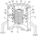
FIG. 2 is a front cross-sectional structural view of the present invention;
FIG. 3 is a schematic top cross-sectional view of the present invention;
FIG. 4 is an enlarged schematic view of the structure of FIG. 1 at A according to the present invention;
FIG. 5 is an enlarged view of the structure of FIG. 2 at B in accordance with the present invention;
FIG. 6 is an enlarged view of the structure of FIG. 3 at C according to the present invention;
fig. 7 is an enlarged view of the structure shown at D in fig. 3 according to the present invention.
In the figure: 1. a barrel; 2. a winding roller; 3. a motor; 4. a rotating shaft; 5. an extrusion mechanism; 51. an electro-hydraulic push rod; 52. a first arc frame; 53. a second arc frame; 54. a rotating drum; 55. a through hole; 56. a first guide frame; 57. a first guide plate; 58. a connecting plate; 59. a first ball bearing; 6. a guide mechanism; 61. a pull rod; 62. a second guide plate; 63. a second guide frame; 64. a second ball bearing; 7. a drying mechanism; 71. an air inlet pipe; 72. a circular tube; 73. a communicating pipe; 74. and (4) a spray head.
Detailed Description
The technical solutions in the embodiments of the present invention will be clearly and completely described below with reference to the drawings in the embodiments of the present invention, and it is obvious that the described embodiments are only a part of the embodiments of the present invention, and not all of the embodiments. All other embodiments, which can be derived by a person skilled in the art from the embodiments given herein without making any creative effort, shall fall within the protection scope of the present invention.
As shown in fig. 1 to 7, the present invention provides a technical solution: the utility model provides a non-woven fabrics dewatering device, including barrel 1, motor 3 is installed to barrel 1's bottom, barrel 1 and fixedly connected with pivot 4 are run through to motor 3's output, and motor 3's output is rotated with barrel 1's bottom and is connected, the surface cover of pivot 4 is equipped with winding roller 2, and winding roller 2 and pivot 4 looks joints, make the surface of pivot 4 personally submit the cross form, and winding roller 2's inner wall set up with four draw-in grooves of 4 surface looks adaptations of pivot, so that motor 3's operation will drive pivot 4 and winding roller 2 together rotatory, and then will twine the non-woven fabrics behind winding roller 2 and carry out dehydration treatment, barrel 1's inner diapire is the boss form, and the drain pipe communicates in barrel 1's bottom, so that collect and discharge water.
The squeezing mechanism 5 and the drying mechanism 7 are arranged in the barrel body 1, the squeezing mechanism 5 comprises an electro-hydraulic push rod 51, a first arc-shaped frame 52 and a second arc-shaped frame 53, the electro-hydraulic push rod 51 is arranged on the outer surface of the barrel body 1, the telescopic end of the electro-hydraulic push rod 51 penetrates through the barrel body 1 and extends into the barrel body 1, the first arc-shaped frame 52 is fixedly connected with the telescopic end of the electro-hydraulic push rod 51, the first arc-shaped frame 52 and the second arc-shaped frame 53 are respectively positioned at the front side and the rear side of the winding roller 2, the inner walls of the first arc-shaped frame 52 and the second arc-shaped frame 53 are rotatably connected with rotary drums 54 which are arranged at equal intervals, the rotary drums 54 can be contacted with non-woven fabrics, when the non-woven fabrics follow the winding roller 2 to rotate, the rotary drums 54 are stirred together to rotate, the stability of the non-woven fabrics during dewatering is ensured, the non-woven fabrics are prevented from being wrinkled, through holes 55 which are arranged at equal intervals are arranged on the outer surfaces of the first arc-shaped frame 52 and the second arc-shaped frame 53, so that the moisture in the non-woven fabrics gets rid of to the outside of first arc frame 52 and second arc frame 53, avoids moisture to remain in first arc frame 52 and second arc frame 53, and the surface of second arc frame 53 is provided with guiding mechanism 6.
The extrusion mechanism 5 further comprises two first guide frames 56, the outer surfaces of the first arc-shaped frame 52 and the second arc-shaped frame 53 are hinged with two symmetrical connecting plates 58, each first guide frame 56 is fixedly connected to the inner wall of the barrel body 1, the two first guide frames 56 are symmetrical to each other, the two first guide frames 56 are respectively located on the left side and the right side of the winding roller 2, the inner wall of each first guide frame 56 is slidably connected with a first guide plate 57, the front surface and the back surface of each first guide plate 57 are inlaid with first balls 59, the first balls 59 are slidably connected with the inner wall of the first guide frame 56, the two connecting plates 58 on the first arc-shaped frame 52 and the second arc-shaped frame 53 are hinged with the two first guide plates 57, under the arrangement of the extrusion mechanism 5, the first arc-shaped frame 52 can be gradually pushed to move by the operation of the electro-hydraulic push rod 51, so that the movement of the first arc-shaped frame 52 drives the two first arc-shaped frames 58 on the first arc-shaped frame 52 to respectively push the two first guide connecting plates 58 Plate 57 removes, under the slip of two first deflector 57, will together stimulate two connecting plates 58 on the second arc frame 53 and remove, and then will stimulate second arc frame 53 and be close to winding roller 2, make first arc frame 52 and second arc frame 53 be close to winding roller 2 mutually in step, so that extrude the non-woven fabrics of winding on winding roller 2 gradually, make the faster non-woven fabrics that breaks away from of moisture, when squeezing the non-woven fabrics, make the non-woven fabrics roll on every rotary drum 54, and then the dehydration efficiency of non-woven fabrics has been improved, make the dehydration more abundant of non-woven fabrics.
The guide mechanism 6 comprises a pull rod 61, a second guide plate 62 and a second guide frame 63, the second guide frame 63 is fixedly connected to the inner wall of the cylinder 1, the second guide frame 63 is positioned on the back surface of the second arc-shaped frame 53, the second guide plate 62 is slidably connected to the inner wall of the second guide frame 63, one end of the pull rod 61 is fixedly connected to the front surface of the second guide plate 62, the other end of the pull rod 61 is connected to the back surface of the second arc-shaped frame 53, the second balls 64 are inlaid on the left side surface and the right side surface of the second guide plate 62, the second balls 64 are slidably connected with the inner wall of the second guide frame 63, through the arrangement of the guide mechanism 6, when the second arc-shaped frame 53 moves, the pull rod 61 can be pulled to slide the second guide plate 62 on the inner wall of the second guide frame 63, and the two second balls 64 can slide with the inner wall of the second guide frame 63, and have a limiting effect on the second guide plate 62, the second arc frame 53 is more stable when moving, the drying mechanism 7 comprises an air inlet pipe 71, a circular pipe 72 and communication pipes 73 in a circumferential array, the circular pipe 72 is fixedly connected to the inner wall of the barrel body 1, one end of the air inlet pipe 71 penetrates through the barrel body 1 and is fixedly communicated with the circular pipe 72, each communication pipe 73 is fixedly communicated with the bottom surface of the circular pipe 72, the communication pipes 73 are connected with the inner wall of the barrel body 1, spray heads 74 which are arranged equidistantly are fixedly communicated with the outer surface of each communication pipe 73, the spray heads 74 are inclined downwards, so that the hot air sprayed by the spray heads 74 can spirally dry the non-woven fabric, the output end of an external hot air blower can be communicated with the air inlet pipe 71 through the arrangement of the drying mechanism 7, the hot air is conveyed into each communication pipe 73 through the circular pipe 72 and is finally sprayed out through the spray heads 74, so as to conveniently dry the non-woven fabric in dehydration, thereby improving the dehydration efficiency of the non-woven fabrics and leading the device to have more practicability.
The working principle is as follows: when the non-woven fabric dewatering device is used, firstly, non-woven fabric to be dewatered is wound on the winding roller 2, then the winding roller 2 is sleeved on the rotating shaft 4, the power supply of the electro-hydraulic push rod 51 and the motor 3 is switched on, so that the rotating shaft 4 and the winding roller 2 are driven to rotate together by the operation of the motor 3, the non-woven fabric can be dewatered, then the first arc-shaped frame 52 is gradually pushed to move by the operation of the electro-hydraulic push rod 51, the two connecting plates 58 on the second arc-shaped frame 53 are respectively pushed to move by the movement of the first arc-shaped frame 52 driving the two connecting plates 58 on the first arc-shaped frame 52, the two connecting plates 58 on the second arc-shaped frame 53 are pulled to move together under the sliding of the two first guide plates 57, and then the second arc-shaped frame 53 is pulled to approach the winding roller 2, so that the first arc-shaped frame 52 and the second arc-shaped frame 53 approach the winding roller 2 synchronously, so that the non-woven fabric wound on the winding roller 2 is gradually squeezed, the water is separated from the non-woven fabric more quickly, when the second arc frame 53 moves, the pull rod 61 is pulled to make the second guide plate 62 slide on the inner wall of the second guide frame 63, and the two second balls 64 can slide with the inner wall of the second guide frame 63, and the second guide plate 62 is limited, so that the second arc frame 53 is more stable when moving, the non-woven fabric can roll on each drum 54 while being extruded, thereby improving the dehydration efficiency of the non-woven fabric, ensuring that the dehydration of the non-woven fabric is more sufficient, the output end of the external hot air blower is communicated with the air inlet pipe 71, so that the hot air is conveyed into each communicating pipe 73 through the circular pipe 72 and finally is sprayed out through the spray head 74, so as to dry the non-woven fabrics in the dehydration, and then improve the dehydration efficiency to the non-woven fabrics, make the device more have the practicality.
Claims (6)
1. The utility model provides a non-woven fabrics dewatering device, includes barrel (1), its characterized in that: motor (3) are installed to the bottom of barrel (1), the output of motor (3) runs through barrel (1) and fixedly connected with pivot (4), and the output of motor (3) rotates with the bottom of barrel (1) and is connected, the surface cover of pivot (4) is equipped with winding roller (2), and winding roller (2) and pivot (4) looks joint, the inside of barrel (1) is provided with extrusion mechanism (5) and stoving mechanism (7).
2. The nonwoven fabric dewatering apparatus of claim 1, wherein: the inner bottom wall of the barrel body (1) is in a boss shape, and the drain pipe is communicated with the bottom of the barrel body (1).
3. The nonwoven fabric dewatering apparatus of claim 1, wherein: the extrusion mechanism (5) comprises an electro-hydraulic push rod (51), a first arc-shaped frame (52) and a second arc-shaped frame (53), the electro-hydraulic push rod (51) is arranged on the outer surface of the barrel body (1), and the telescopic end of the electro-hydraulic push rod (51) penetrates through the cylinder body (1) and extends to the inside of the cylinder body (1), the first arc-shaped frame (52) is fixedly connected with the telescopic end of the electro-hydraulic push rod (51), the first arc-shaped frame (52) and the second arc-shaped frame (53) are respectively positioned at the front side and the rear side of the winding roller (2), the inner walls of the first arc-shaped frame (52) and the second arc-shaped frame (53) are both rotationally connected with rotating cylinders (54) which are arranged at equal intervals, the outer surfaces of the first arc-shaped frame (52) and the second arc-shaped frame (53) are respectively provided with through holes (55) which are arranged at equal intervals, and a guide mechanism (6) is arranged on the outer surface of the second arc-shaped frame (53).
4. The nonwoven fabric dewatering apparatus of claim 3, wherein: the extrusion mechanism (5) further comprises two first guide frames (56), the outer surfaces of the first arc-shaped frame (52) and the second arc-shaped frame (53) are hinged with two symmetrical connecting plates (58), each first guide frame (56) is fixedly connected to the inner wall of the cylinder body (1), the two first guide frames (56) are mutually symmetrical, and the two first guide frames (56) are respectively positioned at the left side and the right side of the winding roller (2), the inner wall of each first guide frame (56) is connected with a first guide plate (57) in a sliding way, the front surface and the back surface of each first guide plate (57) are embedded with first ball bearings (59), and the first ball (59) is connected with the inner wall of the first guide frame (56) in a sliding way, the two connecting plates (58) on the first arc-shaped frame (52) and the second arc-shaped frame (53) are respectively hinged with the two first guide plates (57).
5. The nonwoven fabric dewatering apparatus of claim 3, wherein: guiding mechanism (6) include pull rod (61), second deflector (62) and second guide frame (63), second guide frame (63) fixed connection is in the inner wall of barrel (1), and second guide frame (63) are located the back of second arc frame (53), second deflector (62) sliding connection is in the inner wall of second guide frame (63), the one end fixed connection of pull rod (61) is in the front of second deflector (62), the other end of pull rod (61) is connected with the back of second arc frame (53), the left and right sides face of second deflector (62) all inlays second ball (64), and the inner wall sliding connection of second ball (64) and second guide frame (63).
6. The nonwoven fabric dewatering apparatus of claim 1, wherein: stoving mechanism (7) are including communicating pipe (73) of air-supply line (71), circular pipe (72) and circumference array, circular pipe (72) fixed connection is in the inner wall of barrel (1), the one end of air-supply line (71) run through barrel (1) and with the fixed intercommunication of circular pipe (72), every communicating pipe (73) all fixed intercommunication in the bottom surface of circular pipe (72), and communicating pipe (73) are connected with the inner wall of barrel (1), the surface of every communicating pipe (73) all fixed intercommunication has shower nozzle (74) that the equidistance was arranged.
Priority Applications (1)
| Application Number | Priority Date | Filing Date | Title |
|---|---|---|---|
| CN202122534286.XU CN216204733U (en) | 2021-10-21 | 2021-10-21 | Non-woven fabric dewatering device |
Applications Claiming Priority (1)
| Application Number | Priority Date | Filing Date | Title |
|---|---|---|---|
| CN202122534286.XU CN216204733U (en) | 2021-10-21 | 2021-10-21 | Non-woven fabric dewatering device |
Publications (1)
| Publication Number | Publication Date |
|---|---|
| CN216204733U true CN216204733U (en) | 2022-04-05 |
Family
ID=80885942
Family Applications (1)
| Application Number | Title | Priority Date | Filing Date |
|---|---|---|---|
| CN202122534286.XU Active CN216204733U (en) | 2021-10-21 | 2021-10-21 | Non-woven fabric dewatering device |
Country Status (1)
| Country | Link |
|---|---|
| CN (1) | CN216204733U (en) |
Cited By (1)
| Publication number | Priority date | Publication date | Assignee | Title |
|---|---|---|---|---|
| CN114608272A (en) * | 2022-04-14 | 2022-06-10 | 安徽京威纺织服饰有限公司 | Dewatering equipment special for rolled textile cloth and textile cloth roll drying method |
-
2021
- 2021-10-21 CN CN202122534286.XU patent/CN216204733U/en active Active
Cited By (1)
| Publication number | Priority date | Publication date | Assignee | Title |
|---|---|---|---|---|
| CN114608272A (en) * | 2022-04-14 | 2022-06-10 | 安徽京威纺织服饰有限公司 | Dewatering equipment special for rolled textile cloth and textile cloth roll drying method |
Similar Documents
| Publication | Publication Date | Title |
|---|---|---|
| CN108149413B (en) | High-efficient formula textile fabric belt cleaning device | |
| CN208471116U (en) | A kind of automatic dehydration crane that stability is good | |
| CN202466180U (en) | Knitted fabric open-width wet processing unit with oscillating reticular washing cloth guide roller | |
| CN216204733U (en) | Non-woven fabric dewatering device | |
| CN109013522B (en) | Belt cleaning device is used in chinese-medicinal material production and processing | |
| CN212560751U (en) | Drying device is used in weaving that drying efficiency is high | |
| CN109943981A (en) | A kind of spunlace non-woven non-woven fabric production equipment | |
| CN111270455A (en) | Bleaching device and bleaching method of textile fabric for textile processing | |
| CN211921933U (en) | Surface fabric dehydration drying process device | |
| CN116200893B (en) | Dyeing device and process for degradable material polylactic acid PLA | |
| CN208219250U (en) | A kind of ramie washing machine | |
| CN215628735U (en) | Dewatering device is used in organic cotton surface fabric production | |
| CN213931911U (en) | Cloth drying device for textile processing | |
| CN210220393U (en) | Dewatering device is used in textile fabric processing | |
| CN208830040U (en) | A kind of paper machine pressing device | |
| CN102560933A (en) | Water squeezer | |
| CN211921932U (en) | Cloth dewatering device | |
| CN205368737U (en) | Open width dewatering device | |
| CN218329166U (en) | Drying equipment for double-sided plush fabric | |
| CN216409667U (en) | Efficient dewatering device for fabric | |
| CN215856764U (en) | Continuous linen rolling and pressing device | |
| CN219494716U (en) | Energy-saving dryer for textile processing | |
| CN219621413U (en) | Dyeing equipment | |
| CN219342554U (en) | Automatic cleaning hank dyeing machine | |
| CN220304081U (en) | Drying equipment is used in fabrics processing |
Legal Events
| Date | Code | Title | Description |
|---|---|---|---|
| GR01 | Patent grant | ||
| GR01 | Patent grant |