CN216171749U - Phosphogypsum slurry stirring device - Google Patents
Phosphogypsum slurry stirring device Download PDFInfo
- Publication number
- CN216171749U CN216171749U CN202122950385.6U CN202122950385U CN216171749U CN 216171749 U CN216171749 U CN 216171749U CN 202122950385 U CN202122950385 U CN 202122950385U CN 216171749 U CN216171749 U CN 216171749U
- Authority
- CN
- China
- Prior art keywords
- fixedly connected
- face
- rod
- outer side
- hollow
- Prior art date
- Legal status (The legal status is an assumption and is not a legal conclusion. Google has not performed a legal analysis and makes no representation as to the accuracy of the status listed.)
- Active
Links
Images


Landscapes
- Mixers With Rotating Receptacles And Mixers With Vibration Mechanisms (AREA)
Abstract
The utility model relates to the technical field of phosphogypsum stirring, in particular to a phosphogypsum slurry stirring device which comprises a base, wherein the upper end surface in the middle of the base is fixedly connected with a stirring tank, the upper end surface in the middle of the stirring tank is connected with a top cover in a sliding manner, the upper end surface in the middle of the top cover is fixedly connected with a motor, the lower end surface of the motor is rotatably connected with a transmission shaft, the outer side of the transmission shaft is fixedly connected with a stirring blade, the outer side of the transmission shaft is fixedly connected with a hollow rod, and the bottom end in the hollow rod is fixedly connected with a first compression spring; according to the utility model, the motor and the sliding rod are arranged, so that the scraper can be driven to slide on the inner wall of the base, the ardealite slurry at the inner edge of the stirring tank can be driven to fully flow, and the scraper can cut and rub the ardealite slurry attached to the inner wall of the stirring tank when the inner part of the stirring tank is cleaned, so that the cleanliness of the stirring tank during cleaning is increased to a certain extent, and the stirring tank is very practical.
Description
Technical Field
The utility model relates to the technical field of phosphogypsum stirring, in particular to a phosphogypsum slurry stirring device.
Background
The phosphogypsum mainly comprises gray black and gray white, the particle diameter is generally 5-50 mu m, the content of crystal water is 20-25%, the phosphogypsum is solid waste generated in a wet-process phosphoric acid process, the components of the phosphogypsum are mainly calcium sulfate dihydrate, the composition of the phosphogypsum is complex, besides the calcium sulfate, phosphate ore which is not completely decomposed, residual phosphoric acid, fluoride, acid insoluble substances, organic matters and the like are also contained, and the existence of fluorine and the organic matters has the greatest influence on the resource utilization of the phosphogypsum.
However, when the phosphogypsum is produced, water needs to be added into the phosphogypsum for full stirring, but the viscosity of phosphogypsum slurry is high, the phosphogypsum slurry is difficult to be fully and uniformly stirred by a common stirring tank, and after the stirring is finished, a part of the phosphogypsum slurry is attached to the inner wall of the stirring tank, so that the cleaning difficulty is high; meanwhile, the phosphogypsum slurry is high in viscosity, and the phosphogypsum slurry which is uniformly stirred and mixed can be clamped at a slope below the inner part of the base and cannot flow out of the stirring tank.
SUMMERY OF THE UTILITY MODEL
The utility model aims to provide a phosphogypsum slurry stirring device to solve the problems in the background technology.
In order to achieve the purpose, the utility model provides the following technical scheme:
a phosphogypsum slurry stirring device comprises a base, wherein a stirring tank is fixedly connected to the upper end face in the middle of the base, a top cover is slidably connected to the upper end face in the middle of the stirring tank, a motor is fixedly connected to the upper end face in the middle of the top cover, a transmission shaft is rotatably connected to the lower end face of the motor, stirring blades are fixedly connected to the outer side of the transmission shaft, a hollow rod is fixedly connected to the outer side of the transmission shaft, a first compression spring is fixedly connected to the bottom end inside the hollow rod, a sliding rod is fixedly connected to the top end outside the first compression spring, a scraping plate is fixedly connected to the top end outside the sliding rod, a hollow shell is fixedly connected to the upper end face on the left side of the base, a vertical motor is fixedly connected to the lower portion inside the hollow shell, a cam is rotatably connected to the outer side of the vertical motor, a sliding plate is slidably connected to the outer side above the cam, and a fixing rod is fixedly connected to the upper end face of the sliding plate, the fixing rod upper end face is fixedly connected with a fixing ring, and the fixing ring upper end face is fixedly connected with a jacking block.
Preferably, the middle of the inside of the top cover is rotatably connected with a transmission shaft, the outer side of the sliding rod is slidably connected with a hollow rod, the inside of the sliding rod is fixedly connected with a vibration motor, the outer side of the scraper is slidably connected with a stirring tank, the left side and the right side of the sliding plate are slidably connected with hollow shells, the outer side of the fixed rod is slidably connected with hollow shells, a hollow block is fixedly connected with the upper end face of the right side of the base, a second compression spring is fixedly connected with the inner lower part of the hollow block, and a fixed rod is fixedly connected with the upper end face of the second compression spring.
Preferably, the quantity of cavity pole and scraper blade is 2, and cavity pole and scraper blade are located the left and right sides in the transmission shaft below outside, and the length of scraper blade is the same with the inside perpendicular inner wall length of agitator tank.
Preferably, the vibration motor is electrically connected with the motor, a rubber ring is fixedly connected to the outer side of the right end face of the hollow rod, and a sliding rod is slidably connected to the inner side of the rubber ring.
Preferably, a slope inclining to the inner side by 45 degrees is arranged below the inner part of the stirring tank, and a strip-shaped sliding groove is arranged on the slope surface side below the inner part of the stirring tank.
Preferably, the quantity of dead lever and kicking block is 2, and the left and right sides of dead lever distribution terminal surface under solid fixed ring, and the kicking block distributes in the left and right sides of solid fixed ring up end.
Preferably, the top block up end fixedly connected with block rubber, and the material of block rubber is white hard rubber, and solid fixed ring and dead lever are the vertical state.
Compared with the prior art, the utility model has the beneficial effects that:
1. according to the utility model, the motor and the sliding rod are arranged, so that the scraper can be driven to slide on the inner wall of the base, the ardealite slurry at the inner edge of the stirring tank can be driven to fully flow, the scraper can also cut and rub the ardealite slurry attached to the inner wall of the stirring tank when the inner part of the stirring tank is cleaned, the cleanliness of the stirring tank during cleaning is increased to a certain extent, meanwhile, the vibrating motor is arranged in the sliding rod, and when the sliding rod drives the scraper to move, the vibrating motor can increase the mixing speed of the ardealite slurry, so that the novel ardealite cleaning machine is very practical;
2. according to the utility model, through the vertical motor and the fixed rods, the fixed ring and the top block above the fixed ring can be driven to knock the inclined part at the bottom of the stirring tank, so that phosphogypsum slurry clamped at the inclined part of the inner wall of the stirring tank flows out of a discharge port of the stirring tank through vibration, meanwhile, the number of the fixed rods is 2, the fixed rods are distributed on the left side and the right side below the fixed ring, the fixed rods on the left side are connected with the sliding plate above the vertical motor, the fixed rods on the right side are connected with the second compression spring inside the hollow block, and the fixed ring can be more stable when sliding up and down, so that the vertical motor and the fixed ring fixing device are very practical.
Drawings
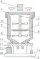
FIG. 1 is a schematic view of the overall structure of the present invention;
FIG. 2 is a schematic view of the internal structure of the hollow rod of the present invention;
FIG. 3 is a schematic view of the structure below the inner wall of the stirring tank of the present invention;
FIG. 4 is a schematic view of the internal structure of the hollow shell according to the present invention;
FIG. 5 is a schematic diagram of the internal structure of the hollow block of the present invention;
fig. 6 is a schematic perspective view of the retaining ring of the present invention.
In the figure: 1-base, 2-stirring tank, 3-top cover, 4-motor, 5-transmission shaft, 6-stirring blade, 7-hollow rod, 8-sliding rod, 9-scraper, 10-hollow shell, 11-fixed rod, 12-fixed ring, 13-hollow block, 14-top block, 15-first compression spring, 16-vibration motor, 17-vertical motor, 18-cam, 19-sliding plate and 20-second compression spring.
Detailed Description
The technical solutions in the embodiments of the present invention will be clearly and completely described below with reference to the drawings in the embodiments of the present invention, and it is obvious that the described embodiments are only a part of the embodiments of the present invention, and not all of the embodiments. All other embodiments, which can be derived by a person skilled in the art from the embodiments given herein without making any creative effort, shall fall within the protection scope of the present invention.
Referring to fig. 1-6, the present invention provides a technical solution:
a phosphogypsum slurry stirring device comprises a base 1, wherein the upper end surface in the middle of the base 1 is fixedly connected with a stirring tank 2, the upper end surface of the stirring tank 2 is slidably connected with a top cover 3, the upper end surface in the middle of the top cover 3 is fixedly connected with a motor 4, the lower end surface of the motor 4 is rotatably connected with a transmission shaft 5, the outer side of the transmission shaft 5 is fixedly connected with a stirring blade 6, the outer side of the transmission shaft 5 is fixedly connected with a hollow rod 7, the bottom end in the hollow rod 7 is fixedly connected with a first compression spring 15, the top end of the outer side of the first compression spring 15 is fixedly connected with a sliding rod 8, the top end of the outer side of the sliding rod 8 is fixedly connected with a scraping plate 9, the upper end surface on the left side of the base 1 is fixedly connected with a hollow shell 10, the lower part in the hollow shell 10 is fixedly connected with a vertical motor 17, the outer side of the vertical motor 17 is rotatably connected with a cam 18, the outer side above the cam 18 is slidably connected with a sliding plate 19, and the upper end surface of the sliding plate 19 is fixedly connected with a fixing rod 11, the upper end face of the fixing rod 11 is fixedly connected with a fixing ring 12, and the upper end face of the fixing ring 12 is fixedly connected with a top block 14.
A transmission shaft 5 is rotatably connected in the middle inside the top cover 3, a hollow rod 7 is slidably connected on the outer side of the sliding rod 8, a vibration motor 16 is fixedly connected in the sliding rod 8, a stirring tank 2 is slidably connected on the outer side of the scraping plate 9, hollow shells 10 are slidably connected on the left side and the right side of the sliding plate 19, a hollow shell 10 is slidably connected on the outer side of the fixed rod 11, a hollow block 13 is fixedly connected on the upper end surface on the right side of the base 1, a second compression spring 20 is fixedly connected below the inner part of the hollow block 13, a fixed rod 11 is fixedly connected on the upper end surface of the second compression spring 20, the number of the hollow rods 7 and the scraping plates 9 is 2, the hollow rods 11 and the scraping plates 9 are positioned on the left side and the right side of the outer side below the transmission shaft 5, the length of the scraping plates 9 is the same as the length of the vertical inner wall inside the stirring tank 2, the vibration motor 16 is electrically connected with the motor 4, a rubber ring is fixedly connected on the outer side of the right end surface of the hollow rod 7, and the inner side of the rubber ring is slidably connected with the sliding rod 8, the phosphogypsum cleaning machine can drive a scraper 9 to slide on the inner wall of a base 1, not only can the phosphogypsum slurry on the inner edge of a stirring tank 2 be driven to fully flow, but also when the interior of the stirring tank 2 is cleaned, the phosphogypsum slurry attached to the inner wall of the stirring tank 2 can be scraped by the scraper 9, the cleanliness of the stirring tank (2) during cleaning is increased to a certain extent, meanwhile, a vibration motor 16 is arranged in a sliding rod 8, when the sliding rod 8 drives the scraper 9 to move, the mixing speed of the phosphogypsum slurry can be increased by the vibration motor 16, a slope which inclines inwards by 45 degrees is arranged below the stirring tank 2, a strip-shaped chute is arranged on the surface side of the slope below the interior of the stirring tank 2, the quantity of fixing rods 11 and the quantity of jacking blocks 14 are 2, the fixing rods 11 are distributed on the left side and the right side of the lower end face of a fixing ring 12, the jacking blocks 14 are distributed on the left side and the right side of the upper end face of the fixing ring 12, and rubber blocks are fixedly connected on the upper end face of the jacking blocks 14, and the material of block rubber is white hard rubber, and solid fixed ring 12 is the vertical state with dead lever 11, can drive solid fixed ring 12 and the kicking block 14 of solid fixed ring 12 top and strike the 2 bottom inclinations of agitator tank, let the ardealite ground paste of card in 2 inner wall inclinations of agitator tank flow from the discharge gate of agitator tank 2 through vibrations, the quantity of dead lever 11 is 2 simultaneously, distribute in the left and right sides of solid fixed ring 12 below, and left dead lever 11 is then connected with the sliding plate 8 above vertical motor 17, dead lever 11 on right side is then connected with the inside second compression spring 20 of cavity piece 13, can let solid fixed ring 12 more stable when sliding from top to bottom, and is very practical.
The working process is as follows: when mixing phosphogypsum slurry, pouring phosphogypsum powder and water into a stirring tank 2 according to a certain proportion, opening a motor 4 above a top cover 3, starting a vibration motor 16 in a sliding rod 8 when the motor 4 is started, driving a transmission shaft 5 to rotate by the motor 4, stirring the phosphogypsum slurry by a stirring blade 6 outside the transmission shaft 5, driving a hollow rod 7 and a scraper 9 to slide on the inner wall of a base 1 by the hollow rod 7 outside the transmission shaft 5, not only driving the phosphogypsum slurry on the inner edge of the stirring tank 2 to fully flow, but also scraping the slurry attached to the inner wall of the stirring tank 2 by the scraper 9 when cleaning the inside of the stirring tank 2, increasing the cleanliness of the stirring tank 2 when cleaning to a certain extent, if the phosphogypsum slurry flows out from a discharge port of the stirring tank 2 after being mixed, and is clamped at a slope position below the inner wall of the stirring tank 2, opening a vertical motor 17 inside a hollow shell 10, the vertical motor 17 drives the cam 18 on the outer side to rotate, the sliding plate 19 above the outer side of the cam 18 is moved up and down by irregular movement of the cam 18, the fixing rod 11 above the sliding plate 19 drives the fixing ring 12 to move up, the top block 14 above the fixing ring 12 strikes the inclined part at the bottom of the stirring tank 2, and phosphogypsum slurry clamped at the inclined part on the inner wall of the stirring tank 2 flows out of the discharge hole of the stirring tank 2 through vibration, so that the vertical motor is very practical.
Although embodiments of the present invention have been shown and described, it will be appreciated by those skilled in the art that changes, modifications, substitutions and alterations can be made in these embodiments without departing from the principles and spirit of the utility model, the scope of which is defined in the appended claims and their equivalents.
Claims (7)
1. The utility model provides a phosphogypsum slurry stirring device, includes base (1), its characterized in that: the stirring device is characterized in that the stirring tank (2) is fixedly connected to the middle upper end face of the base (1), the top cover (3) is slidably connected to the upper end face of the stirring tank (2), the motor (4) is fixedly connected to the middle upper end face of the top cover (3), the transmission shaft (5) is rotatably connected to the lower end face of the motor (4), the stirring blade (6) is fixedly connected to the outer side of the transmission shaft (5), the hollow rod (7) is fixedly connected to the outer side of the transmission shaft (5), the first compression spring (15) is fixedly connected to the inner bottom end of the hollow rod (7), the sliding rod (8) is fixedly connected to the outer top end of the sliding rod (8), the hollow shell (10) is fixedly connected to the upper end face of the left side of the base (1), and the vertical motor (17) is fixedly connected to the inner lower portion of the hollow shell (10), the vertical motor is characterized in that a cam (18) is rotatably connected to the outer side of the vertical motor (17), a sliding plate (19) is slidably connected to the outer side above the cam (18), a fixing rod (11) is fixedly connected to the upper end face of the sliding plate (19), a fixing ring (12) is fixedly connected to the upper end face of the fixing rod (11), and a top block (14) is fixedly connected to the upper end face of the fixing ring (12).
2. The phosphogypsum slurry stirring device according to claim 1, which is characterized in that: the improved multifunctional scraper is characterized in that a transmission shaft (5) is rotatably connected to the middle of the inside of the top cover (3), a hollow rod (7) is slidably connected to the outer side of the sliding rod (8), a vibrating motor (16) is fixedly connected to the inside of the sliding rod (8), a stirring tank (2) is slidably connected to the outer side of the scraping plate (9), hollow shells (10) are slidably connected to the left side and the right side of the sliding plate (19), hollow shells (10) are slidably connected to the outer side of the fixing rod (11), a hollow block (13) is fixedly connected to the upper end face of the right side of the base (1), a second compression spring (20) is fixedly connected to the inner lower portion of the hollow block (13), and a fixing rod (11) is fixedly connected to the upper end face of the second compression spring (20).
3. The phosphogypsum slurry stirring device according to claim 1, which is characterized in that: the quantity of cavity pole (7) and scraper blade (9) is 2, and cavity pole (7) and scraper blade (9) are located the left and right sides in transmission shaft (5) below outside, and the length of scraper blade (9) is the same with agitator tank (2) inside perpendicular inner wall length.
4. An phosphogypsum slurry stirring device according to claim 2, characterised in that: the vibration motor (16) is electrically connected with the motor (4), a rubber ring is fixedly connected to the outer side of the right end face of the hollow rod (7), and a sliding rod (8) is slidably connected to the inner side of the rubber ring.
5. The phosphogypsum slurry stirring device according to claim 1, which is characterized in that: the inside below of agitator tank (2) is equipped with the slope of 45 degrees of inboard slope, and the slope table side of the inside below of agitator tank (2) is equipped with the bar spout.
6. The phosphogypsum slurry stirring device according to claim 1, which is characterized in that: the quantity of dead lever (11) and kicking block (14) is 2, and dead lever (11) distribute the left and right sides at solid fixed ring (12) lower extreme face, and kicking block (14) distribute the left and right sides at solid fixed ring (12) up end.
7. The phosphogypsum slurry stirring device according to claim 1, which is characterized in that: the upper end face of the top block (14) is fixedly connected with a rubber block, the rubber block is made of white hard rubber, and the fixing ring (12) and the fixing rod (11) are in a vertical state.
Priority Applications (1)
| Application Number | Priority Date | Filing Date | Title |
|---|---|---|---|
| CN202122950385.6U CN216171749U (en) | 2021-11-29 | 2021-11-29 | Phosphogypsum slurry stirring device |
Applications Claiming Priority (1)
| Application Number | Priority Date | Filing Date | Title |
|---|---|---|---|
| CN202122950385.6U CN216171749U (en) | 2021-11-29 | 2021-11-29 | Phosphogypsum slurry stirring device |
Publications (1)
| Publication Number | Publication Date |
|---|---|
| CN216171749U true CN216171749U (en) | 2022-04-05 |
Family
ID=80914270
Family Applications (1)
| Application Number | Title | Priority Date | Filing Date |
|---|---|---|---|
| CN202122950385.6U Active CN216171749U (en) | 2021-11-29 | 2021-11-29 | Phosphogypsum slurry stirring device |
Country Status (1)
| Country | Link |
|---|---|
| CN (1) | CN216171749U (en) |
Cited By (1)
| Publication number | Priority date | Publication date | Assignee | Title |
|---|---|---|---|---|
| CN116444121A (en) * | 2023-04-24 | 2023-07-18 | 江苏博一环保科技有限公司 | Heat pump sludge drying device for preventing sludge from agglomerating into large blocks |
-
2021
- 2021-11-29 CN CN202122950385.6U patent/CN216171749U/en active Active
Cited By (1)
| Publication number | Priority date | Publication date | Assignee | Title |
|---|---|---|---|---|
| CN116444121A (en) * | 2023-04-24 | 2023-07-18 | 江苏博一环保科技有限公司 | Heat pump sludge drying device for preventing sludge from agglomerating into large blocks |
Similar Documents
| Publication | Publication Date | Title |
|---|---|---|
| CN211098487U (en) | Asphalt emulsifying equipment with stirring function | |
| CN216171749U (en) | Phosphogypsum slurry stirring device | |
| CN210960140U (en) | Raw material stirring device for bread processing | |
| CN209552124U (en) | A kind of mixing plant of fast solidifying type grouting material | |
| CN210589908U (en) | Concrete material stirrer | |
| CN206687035U (en) | A kind of good flour stranding machine of mixing effect | |
| CN213533205U (en) | Concrete classification stirring device | |
| CN209696751U (en) | A kind of material processing and forming raw material blending device | |
| CN205364223U (en) | Production ground paste agitating unit for aerated concrete | |
| CN208305381U (en) | A kind of cement mixer for building | |
| CN216266816U (en) | Concrete mixing equipment for construction | |
| CN214136686U (en) | Recycled concrete agitating unit | |
| CN205797081U (en) | A kind of serosity processes agitator tank | |
| CN211709670U (en) | Concrete mixing plant discharging device | |
| CN208799978U (en) | A kind of waste and old lead acid accumulator recycling lead mud agitating device | |
| CN207432498U (en) | A kind of batching plant's device for discharging | |
| CN208133285U (en) | A kind of build concrete agitating device | |
| CN208032428U (en) | A kind of fabric fire retardant mixing arrangement | |
| CN215434348U (en) | Civil engineering concrete mixer | |
| CN216230097U (en) | Concrete mixing arrangement for building engineering | |
| CN111775330A (en) | Mortar mixing stirring device with good mixing effect | |
| CN215702842U (en) | Planetary cement mortar mixer | |
| CN220377034U (en) | Asphalt mixture stirring equipment | |
| CN217967612U (en) | Ultrahigh-performance concrete mixing device convenient for feeding | |
| CN220940344U (en) | Efficient mixer |
Legal Events
| Date | Code | Title | Description |
|---|---|---|---|
| GR01 | Patent grant | ||
| GR01 | Patent grant |