CN216139109U - Edge bonding machine capable of automatically feeding for furniture processing - Google Patents
Edge bonding machine capable of automatically feeding for furniture processing Download PDFInfo
- Publication number
- CN216139109U CN216139109U CN202121851650.9U CN202121851650U CN216139109U CN 216139109 U CN216139109 U CN 216139109U CN 202121851650 U CN202121851650 U CN 202121851650U CN 216139109 U CN216139109 U CN 216139109U
- Authority
- CN
- China
- Prior art keywords
- fixedly connected
- base
- block
- moving
- bonding machine
- Prior art date
- Legal status (The legal status is an assumption and is not a legal conclusion. Google has not performed a legal analysis and makes no representation as to the accuracy of the status listed.)
- Active
Links
Images


Landscapes
- Legs For Furniture In General (AREA)
Abstract
The utility model discloses an edge bonding machine capable of automatically feeding and used for furniture processing, which comprises an edge bonding machine body, wherein four corners of the bottom of the edge bonding machine body are fixedly connected with supports, the bottoms of the four supports are fixedly connected with a base, the bottom of the base is fixedly connected with a movable wheel, two sides of an inner cavity of the base are respectively provided with a movable block, the bottom of each movable block is fixedly connected with an adjusting block, and the bottom of each adjusting block penetrates to the bottom of the base. According to the edge bonding machine for furniture processing, the problem that the existing edge bonding machine capable of automatically feeding is low in practicability is solved by arranging the edge bonding machine body, the support, the base, the moving wheel, the moving block, the adjusting block, the positioning block, the limiting box, the first spring, the limiting plate, the limiting rod, the rotating disk, the rotating block, the groove, the motor, the moving shell, the lifting plate, the lifting wheel, the supporting rod, the second spring and the supporting plate.
Description
Technical Field
The utility model relates to the technical field of furniture processing, in particular to an edge bonding machine capable of automatically feeding materials for furniture processing.
Background
Furniture means a large variety of necessary appliances and facilities for maintaining normal life, practicing production practice and developing social activities for people, the furniture is continuously developed and innovated along with the foot steps of the times, the furniture is various in door types, different in material, complete in variety and different in use, and is an important basis for establishing working and living spaces, at present, edge bonding machines are required to be used in the furniture processing process, a plurality of edge bonding machines are additionally provided with conveying devices for realizing automatic feeding conveniently, but most of the existing edge bonding machines have the problem of inconvenient movement, if the existing edge bonding machines are required to be moved conveniently, pulleys are usually arranged at the bottoms of the devices and moved by the pulleys, but because the pulleys are only contacted with the ground for supporting, the stability of the edge bonding machines in operation is poor, the displacement is easy to generate, and if supporting legs are used for supporting, the devices are inconvenient to move, the practicability of the edge bonding machine is reduced.
SUMMERY OF THE UTILITY MODEL
The utility model aims to provide an automatic-feeding edge bonding machine for furniture processing, which has the advantage of high practicability and solves the problem of low practicability of the existing automatic-feeding edge bonding machine for furniture processing.
In order to achieve the purpose, the utility model provides the following technical scheme: an edge bonding machine capable of automatically feeding for furniture processing comprises an edge bonding machine body, wherein four corners of the bottom of the edge bonding machine body are fixedly connected with brackets, the bottoms of the four brackets are fixedly connected with a base, the bottom of the base is fixedly connected with a moving wheel, two sides of an inner cavity of the base are respectively provided with a moving block, the bottom of the moving block is fixedly connected with an adjusting block, the bottom of the adjusting block penetrates through the bottom of the base, one opposite sides of the two adjusting blocks are respectively and fixedly connected with a positioning block, two sides of the inner cavity of the base are respectively and fixedly connected with a limiting box, an inner cavity of the limiting box is provided with a first spring, one side of the first spring, which is close to the moving block, is fixedly connected with a limiting plate, one side of the limiting plate, which is far away from the first spring, is fixedly connected with a limiting rod, one end of the limiting rod, which is far away from the limiting plate, penetrates through the limiting box and is fixedly connected with the moving block, a rotating disk is arranged at the rear side of the moving block, a rotating block is fixedly connected with the top of the front surface of the rotating disk, the back of the moving block is provided with a groove matched with the rotating block, the front side of the rotating block extends to the inner cavity of the groove, the back of the base and the rear side of the rotating disk are fixedly connected with a motor, the front side of the output end of the motor penetrates through the inner cavity of the base and is fixedly connected with the rotating disk, the tops of the opposite sides of the two moving blocks are fixedly connected with moving shells, the bottoms of the two moving shells are provided with lifting plates, the two sides of the top of the lifting plate are fixedly connected with lifting wheels, the top of the lifting wheels extends to the top of the inner cavity of the movable shell, the two sides of the bottom of the lifting plate are both fixedly connected with supporting rods, the surfaces of the supporting rods are sleeved with second springs, the bottom of bracing piece runs through to the bottom of base, the bottom fixedly connected with backup pad of two bracing pieces.
Preferably, the number of the moving wheels is four, the moving wheels are evenly distributed at four corners of the bottom of the base, and the number of the positioning blocks is four.
Preferably, the bottom of the supporting plate is fixedly connected with a first anti-skid pad, and one side of the positioning block is fixedly connected with a second anti-skid pad.
Preferably, the top of the movable shell is fixedly connected with a sliding block, the top of the inner cavity of the base is provided with a sliding groove matched with the sliding block, and the top of the sliding block extends to the inner cavity of the sliding groove.
Preferably, the surface of the moving block is in sliding connection with the inner wall of the base, the surface of the rotating block is in sliding connection with the inner wall of the groove, and the bottom of the base is provided with an opening matched with the adjusting block for use.
Preferably, the bottom of the inner cavity of the base is provided with sliding rods which are fixedly connected with the two sides of the lifting plate, sliding sleeves are sleeved on the surfaces of the sliding rods, and one sides, opposite to the two sliding sleeves, of the two sliding sleeves are fixedly connected with the lifting plate.
Compared with the prior art, the utility model has the following beneficial effects:
1. according to the edge bonding machine for furniture processing, the problem that the existing edge bonding machine capable of automatically feeding is low in practicability is solved by arranging the edge bonding machine body, the support, the base, the moving wheel, the moving block, the adjusting block, the positioning block, the limiting box, the first spring, the limiting plate, the limiting rod, the rotating disk, the rotating block, the groove, the motor, the moving shell, the lifting plate, the lifting wheel, the supporting rod, the second spring and the supporting plate.
2. The edge bonding machine is provided with the bracket, so that the effect of supporting the edge bonding machine body can be achieved, the moving wheel is arranged, the moving of the whole device can be facilitated, the two moving blocks can be conveniently moved towards the middle to reset through the arrangement of the first spring, the rotating block can be conveniently used through the arrangement of the groove, the adjusting of the lifting wheel can be facilitated through the arrangement of the moving shell, the lifting plate can be conveniently moved upwards to reset through the arrangement of the second spring, and the moving stability of the lifting plate can be improved through the arrangement of the sliding rod and the sliding sleeve.
Drawings
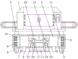
FIG. 1 is a perspective view of the structure of the present invention;
FIG. 2 is a cross-sectional view of the structure of the present invention;
FIG. 3 is a front view of the structure of the present invention;
FIG. 4 is a right side partial cross-sectional view of the base of the present invention;
figure 5 is a rear view of the moving block of the present invention.
In the figure: 1. a bag sealer body; 2. a support; 3. a base; 4. a moving wheel; 5. a moving block; 6. an adjusting block; 7. positioning blocks; 8. a limiting box; 9. a first spring; 10. a limiting plate; 11. a limiting rod; 12. rotating the disc; 13. rotating the block; 14. a groove; 15. a motor; 16. moving the shell; 17. a lifting plate; 18. a lifting wheel; 19. a support bar; 20. a second spring; 21. a support plate; 22. a slide bar; 23. and (4) a sliding sleeve.
Detailed Description
The technical solutions in the embodiments of the present invention will be clearly and completely described below with reference to the drawings in the embodiments of the present invention, and it is obvious that the described embodiments are only a part of the embodiments of the present invention, and not all of the embodiments. All other embodiments, which can be derived by a person skilled in the art from the embodiments given herein without making any creative effort, shall fall within the protection scope of the present invention.
In the description of the present invention, it should be noted that the terms "upper", "lower", "inner", "outer", "front", "rear", "both ends", "one end", "the other end", and the like indicate orientations or positional relationships based on the orientations or positional relationships shown in the drawings, and are only for convenience of describing the present invention and simplifying the description, but do not indicate or imply that the referred device or element must have a specific orientation, be constructed in a specific orientation, and be operated, and thus, should not be construed as limiting the present invention. Furthermore, the terms "first" and "second" are used for descriptive purposes only and are not to be construed as indicating or implying relative importance.
In the description of the present invention, it is to be noted that, unless otherwise explicitly specified or limited, the terms "mounted", "provided", "connected", and the like are to be construed broadly, such as "connected", which may be fixedly connected, detachably connected, or integrally connected; can be mechanically or electrically connected; they may be connected directly or indirectly through intervening media, or they may be interconnected between two elements. The specific meanings of the above terms in the present invention can be understood in specific cases to those skilled in the art.
Referring to fig. 1-5, an edge bonding machine for furniture processing capable of automatically feeding comprises an edge bonding machine body 1, wherein four corners of the bottom of the edge bonding machine body 1 are fixedly connected with brackets 2, the bottoms of the four brackets 2 are fixedly connected with a base 3, the bottom of the base 3 is fixedly connected with a movable wheel 4, two sides of the inner cavity of the base 3 are respectively provided with a movable block 5, the bottom of the movable block 5 is fixedly connected with an adjusting block 6, the bottom of the adjusting block 6 penetrates through the bottom of the base 3, one sides of the two adjusting blocks 6 opposite to each other are respectively fixedly connected with a positioning block 7, two sides of the inner cavity of the base 3 are respectively fixedly connected with a limiting box 8, the inner cavity of the limiting box 8 is provided with a first spring 9, one side of the first spring 9 close to the movable block 5 is fixedly connected with a limiting plate 10, one side of the limiting plate 10 far away from the first spring 9 is fixedly connected with a limiting rod 11, one end of the limiting rod 11 far away from the limiting plate 10 penetrates through the limiting box 8 and is fixedly connected with the movable block 5, the rear side of the moving block 5 is provided with a rotating disk 12, the top of the front surface of the rotating disk 12 is fixedly connected with a rotating block 13, the back of the moving block 5 is provided with a groove 14 matched with the rotating block 13 for use, the front side of the rotating block 13 extends to the inner cavity of the groove 14, the back of the base 3 is fixedly connected with a motor 15 positioned at the rear side of the rotating disk 12, the front side of the output end of the motor 15 penetrates through the inner cavity of the base 3 and is fixedly connected with the rotating disk 12, the tops of the opposite sides of the two moving blocks 5 are fixedly connected with a moving shell 16, the bottoms of the two moving shells 16 are provided with lifting plates 17, the two sides of the tops of the lifting plates 17 are fixedly connected with lifting wheels 18, the tops of the lifting wheels 18 extend to the tops of the inner cavities of the moving shells 16, the two sides of the bottoms of the lifting plates 17 are fixedly connected with supporting rods 19, the surfaces of the supporting rods 19 are sleeved with second springs 20, and the bottoms of the supporting rods 19 penetrate through to the bottom of the base 3, the bottom of the two support rods 19 is fixedly connected with a support plate 21, the number of the moving wheels 4 is four, and the moving wheels are uniformly distributed at four corners of the bottom of the base 3, the number of the positioning blocks 7 is four, the bottom of the support plate 21 is fixedly connected with a first anti-skid pad, one side of the positioning block 7 is fixedly connected with a second anti-skid pad, the top of the moving shell 16 is fixedly connected with a sliding block, the top of the inner cavity of the base 3 is provided with a sliding groove matched with the sliding block for use, the top of the sliding block extends to the inner cavity of the sliding groove, the surface of the moving block 5 is in sliding connection with the inner wall of the base 3, the surface of the rotating block 13 is in sliding connection with the inner wall of the groove 14, the bottom of the base 3 is provided with an opening matched with the adjusting block 6 for use, the bottom of the inner cavity of the base 3 and positioned at two sides of the lifting plate 17 are both fixedly connected with sliding rods 22, the sliding sleeves 23 are sleeved on the surfaces of the sliding rods 22, and one sides opposite to the two sliding sleeves 23 are both fixedly connected with the lifting plate 17, through setting up the support 2, can play the effect of supporting the bag sealer body 1, through setting up the removal wheel 4, can be convenient for the removal of whole device, through setting up the first spring 9, can be convenient for two movable blocks 5 to remove to the centre and reset, through setting up the recess 14, can be convenient for the use of rotatory piece 13, through setting up the removal shell 16, can be convenient for the regulation of lifter 18, through setting up the second spring 20, can be convenient for lifter 17 to move upwards and reset, through setting up slide bar 22 and sliding sleeve 23, can improve the stability that lifter 17 removed, through setting up bag sealer body 1, support 2, base 3, remove wheel 4, movable block 5, regulating block 6, locating piece 7, spacing box 8, first spring 9, limiting plate 10, gag lever post 11, rotary disk 12, rotatory piece 13, recess 14, motor 15, remove shell 16, lifter 17, Lifting wheel 18, bracing piece 19, second spring 20 and backup pad 21 have solved the lower problem of current can automatic feeding's bag sealer practicality for furniture processing, and this bag sealer for furniture processing that can automatic feeding possesses the advantage that the practicality is high.
During the use, can remove whole bag sealer through the cooperation of removing wheel 4, after the bag sealer removed the position that needs, control motor 15 operation drove rotary disk 12 and rotates, rotary disk 12 drives rotatory piece 13 and rotates, rotatory piece 13 can drive movable block 5 through the cooperation of recess 14 and remove, two movable blocks 5 keep away from each other and drive regulating block 6 and removal shell 16 and remove, regulating block 6 drives locating piece 7 and is close to and removes wheel 4 and until pasting tightly, two removal shells 16 keep away from each other and can extrude lifting wheel 18, drive lifting wheel 18 and remove downwards, lifting wheel 18 drives backup pad 21 and removes downwards through the cooperation of lifter plate 17 and bracing piece 19 and is close to ground until pasting tightly.
Although embodiments of the present invention have been shown and described, it will be appreciated by those skilled in the art that changes, modifications, substitutions and alterations can be made in these embodiments without departing from the principles and spirit of the utility model, the scope of which is defined in the appended claims and their equivalents.
Claims (6)
1. The utility model provides a can automatic feeding's bag sealer for furniture processing, includes bag sealer body (1), its characterized in that: the edge bonding machine is characterized in that the four corners of the bottom of the edge bonding machine body (1) are fixedly connected with supports (2), the bottoms of the four supports (2) are fixedly connected with a base (3), the bottom of the base (3) is fixedly connected with a moving wheel (4), the two sides of the inner cavity of the base (3) are respectively provided with a moving block (5), the bottom of each moving block (5) is fixedly connected with an adjusting block (6), the bottom of each adjusting block (6) penetrates through the bottom of the base (3), the opposite sides of the two adjusting blocks (6) are respectively and fixedly connected with a positioning block (7), the two sides of the inner cavity of the base (3) are respectively and fixedly connected with a limiting box (8), the inner cavity of each limiting box (8) is provided with a first spring (9), one side of each first spring (9) close to the corresponding moving block (5) is fixedly connected with a limiting plate (10), and one side of each limiting plate (10) far away from the corresponding first spring (9) is fixedly connected with a limiting rod (11), one end, far away from the limiting plate (10), of the limiting rod (11) penetrates through the limiting box (8) and is fixedly connected with the moving block (5), a rotating disc (12) is arranged on the rear side of the moving block (5), a rotating block (13) is fixedly connected to the top of the front surface of the rotating disc (12), a groove (14) matched with the rotating block (13) for use is formed in the back surface of the moving block (5), the front side of the rotating block (13) extends to an inner cavity of the groove (14), a motor (15) is fixedly connected to the back surface of the base (3) and is positioned on the rear side of the rotating disc (12), the front side of the output end of the motor (15) penetrates through the inner cavity of the base (3) and is fixedly connected with the rotating disc (12), moving shells (16) are fixedly connected to the tops of the opposite sides of the two moving blocks (5), and lifting plates (17) are arranged at the bottoms of the two moving shells (16), the equal fixedly connected with lifting wheel (18) in both sides at lifter plate (17) top, the top of lifting wheel (18) extends to the top of moving shell (16) inner chamber, the equal fixed connection bracing piece (19) in both sides of lifter plate (17) bottom, the surface cover of bracing piece (19) is equipped with second spring (20), the bottom of bracing piece (19) runs through to the bottom of base (3), bottom fixedly connected with backup pad (21) of two bracing pieces (19).
2. The edge bonding machine capable of automatically feeding for furniture processing according to claim 1, wherein: the number of the moving wheels (4) is four, the moving wheels are evenly distributed at four corners of the bottom of the base (3), and the number of the positioning blocks (7) is four.
3. The edge bonding machine capable of automatically feeding for furniture processing according to claim 1, wherein: the bottom of the supporting plate (21) is fixedly connected with a first anti-skid pad, and one side of the positioning block (7) is fixedly connected with a second anti-skid pad.
4. The edge bonding machine capable of automatically feeding for furniture processing according to claim 1, wherein: the top fixedly connected with slider of removal shell (16), the spout that uses with the slider cooperation is seted up at the top of base (3) inner chamber, and the top of slider extends to the inner chamber of spout.
5. The edge bonding machine capable of automatically feeding for furniture processing according to claim 1, wherein: the surface of the moving block (5) is connected with the inner wall of the base (3) in a sliding mode, the surface of the rotating block (13) is connected with the inner wall of the groove (14) in a sliding mode, and the bottom of the base (3) is provided with an opening matched with the adjusting block (6) for use.
6. The edge bonding machine capable of automatically feeding for furniture processing according to claim 1, wherein: the bottom of base (3) inner chamber just is located the equal fixedly connected with slide bar (22) in both sides of lifter plate (17), the surface cover of slide bar (22) is equipped with sliding sleeve (23), and one side that two sliding sleeve (23) are relative all with lifter plate (17) fixed connection.
Priority Applications (1)
| Application Number | Priority Date | Filing Date | Title |
|---|---|---|---|
| CN202121851650.9U CN216139109U (en) | 2021-08-10 | 2021-08-10 | Edge bonding machine capable of automatically feeding for furniture processing |
Applications Claiming Priority (1)
| Application Number | Priority Date | Filing Date | Title |
|---|---|---|---|
| CN202121851650.9U CN216139109U (en) | 2021-08-10 | 2021-08-10 | Edge bonding machine capable of automatically feeding for furniture processing |
Publications (1)
| Publication Number | Publication Date |
|---|---|
| CN216139109U true CN216139109U (en) | 2022-03-29 |
Family
ID=80805423
Family Applications (1)
| Application Number | Title | Priority Date | Filing Date |
|---|---|---|---|
| CN202121851650.9U Active CN216139109U (en) | 2021-08-10 | 2021-08-10 | Edge bonding machine capable of automatically feeding for furniture processing |
Country Status (1)
| Country | Link |
|---|---|
| CN (1) | CN216139109U (en) |
-
2021
- 2021-08-10 CN CN202121851650.9U patent/CN216139109U/en active Active
Similar Documents
| Publication | Publication Date | Title |
|---|---|---|
| CN110091159A (en) | A kind of mobile phone tears screen device open automatically | |
| CN207206545U (en) | A kind of capsule trimming device of capsule production equipment | |
| CN216139109U (en) | Edge bonding machine capable of automatically feeding for furniture processing | |
| CN211406925U (en) | Green belt trimming means for municipal construction | |
| CN209290843U (en) | A kind of anesthetic liquid medicine syringe sealed in unit | |
| CN215149495U (en) | Full-automatic multifunctional vegetable cutter | |
| CN207088055U (en) | A kind of automatic planer tool apparatus of Furniture manufacture | |
| CN213795227U (en) | Cutting device of coil of strip | |
| CN109533942A (en) | A kind of automatic meal selling device that can be filled a bowl with rice automatically | |
| CN213290546U (en) | Cutting device of foam for oil painting | |
| CN212021094U (en) | Edge banding machine with limiting function for furniture processing | |
| CN215506216U (en) | High-efficient environmental protection indoor formaldehyde removing construction machine | |
| CN211795584U (en) | Traditional chinese medicine warehouse management is with goods shelves convenient to remove | |
| CN215748242U (en) | Full-automatic deburring machine with self-cleaning function | |
| CN211303651U (en) | Mirror surface edge bonding machine that sealing performance is good | |
| CN210846547U (en) | Grinder is used in food essence processing | |
| CN216227944U (en) | Industrial automation line convenient to overhaul | |
| CN216050637U (en) | Nozzle water distribution testing device | |
| CN215410867U (en) | Automatic filling machine of high accuracy ration regulation and control | |
| CN216615093U (en) | Automatic sewing machine that machining efficiency is high | |
| CN214216207U (en) | Metering type liquid medicine filling device for anesthesia department | |
| CN216575881U (en) | Precision machinery engineering is with cnc engraving and milling machine that possesses automatic clearance sweeps function | |
| CN216735032U (en) | Intelligent double-station efficient and stable high-speed edge sealing machine for packaging engineering | |
| CN209290837U (en) | One seed ginseng medicine processes automated packaging equipment | |
| CN210874138U (en) | Evaporation plant is used in food essence processing |
Legal Events
| Date | Code | Title | Description |
|---|---|---|---|
| GR01 | Patent grant | ||
| GR01 | Patent grant |