CN216137279U - Efficient recycled concrete apparatus for producing for green building construction - Google Patents
Efficient recycled concrete apparatus for producing for green building construction Download PDFInfo
- Publication number
- CN216137279U CN216137279U CN202122025345.0U CN202122025345U CN216137279U CN 216137279 U CN216137279 U CN 216137279U CN 202122025345 U CN202122025345 U CN 202122025345U CN 216137279 U CN216137279 U CN 216137279U
- Authority
- CN
- China
- Prior art keywords
- fixedly connected
- crushing
- box
- recycled concrete
- building construction
- Prior art date
- Legal status (The legal status is an assumption and is not a legal conclusion. Google has not performed a legal analysis and makes no representation as to the accuracy of the status listed.)
- Active
Links
Images

Abstract
The utility model discloses an efficient recycled concrete production device for green building construction, which comprises a bottom plate, wherein a crushing box is fixedly connected to the left side of the top of the bottom plate, a conveying box is fixedly connected to the middle end of the top of the bottom plate, a stirring box is fixedly connected to the right side of the top of the bottom plate, air cylinders are fixedly connected to the tops of the left side and the right side of the inner wall of the crushing box, the output ends of the air cylinders are fixedly connected with a rolling plate, a first rotating motor is fixedly connected to the left side of the front surface of the crushing box, and the output end of the first rotating motor penetrates into the inner cavity of the crushing box. The utility model is provided with the cylinder, the rolling plate, the first rotating motor, the first crushing roller, the second crushing roller, the punching screen, the servo motor, the auger feeding mechanism, the second rotating motor, the stirring rod and the stirring blade, and solves the problem that the existing concrete stirring device is not convenient for people to use because of unsatisfactory working efficiency when in use.
Description
Technical Field
The utility model relates to the technical field of building construction, in particular to a high-efficiency recycled concrete production device for green building construction.
Background
The construction is a production activity in the construction implementation stage of engineering construction, is a construction process of various buildings, and can also be a process of changing various lines on a design drawing into a real object at a specified place.
SUMMERY OF THE UTILITY MODEL
Aiming at the defects of the prior art, the utility model provides an efficient recycled concrete production device for green building construction, which has the advantage of high working efficiency and solves the problem that the existing concrete stirring device is not ideal in working efficiency when in use, so that the device is inconvenient for people to use.
In order to achieve the purpose, the utility model provides the following technical scheme: an efficient recycled concrete production device for green building construction comprises a base plate, wherein a crushing box is fixedly connected to the left side of the top of the base plate, a conveying box is fixedly connected to the middle end of the top of the base plate, an agitating box is fixedly connected to the right side of the top of the base plate, air cylinders are fixedly connected to the tops of the left side and the right side of the inner wall of the crushing box, a rolling plate is fixedly connected to the output end of each air cylinder, a first rotating motor is fixedly connected to the left side of the front surface of the crushing box, the output end of the first rotating motor penetrates into the inner cavity of the crushing box, a first crushing roller is fixedly connected to the surface of the output end of the first rotating motor, a second crushing roller is movably connected to the right side of the first crushing roller through a rotating shaft, the first crushing roller is meshed with the second crushing roller through crushing teeth, and a second rotating motor is fixedly connected to the top of the agitating box, the output fixedly connected with puddler of second rotation motor, and the fixed surface of puddler is connected with a plurality of the same and evenly distributed's of size stirring vane.
Preferably, the top fixedly connected with servo motor of delivery box, servo motor's output runs through to the inner chamber of delivery box in, and servo motor's output fixedly connected with auger feeding mechanism.
Preferably, the bottom on crushing case right side and the left bottom of transfer case have all seted up the pan feeding mouth, smash and communicate through the pan feeding mouth between case and the transfer case, the discharge gate has all been seted up with the left top of agitator tank in the top on transfer case right side, and communicates through the discharge gate between transfer case and the agitator tank.
Preferably, the top intercommunication of smashing the case has the inlet pipe, the top intercommunication of inlet pipe has the horn tube, the below that smashes the left and right sides of incasement wall and be located the board of rolling all slopes and is provided with first guide plate, the equal fixedly connected with cassette in bottom of smashing the incasement wall left and right sides, the inner chamber joint of cassette has the otter board that punches a hole.
Preferably, the left side intercommunication at agitator tank top has the inlet tube, the bottom intercommunication on agitator tank right side has the discharging pipe, and the right side threaded connection of discharging pipe has sealed lid.
Preferably, the bottom of smashing incasement wall and the bottom of carrying incasement wall all incline to be provided with the second guide plate, there is the chamber door bottom of smashing the case obverse surface through hinge swing joint, the obverse surface of agitator tank inlays and has the observation board.
Compared with the prior art, the utility model provides an efficient recycled concrete production device for green building construction, which has the following beneficial effects:
1. the utility model is provided with an air cylinder and a rolling plate, the output ends of the air cylinders at two sides simultaneously extend inwards to drive the rolling plate to move inwards to extrude and crush recycled concrete raw materials, the utility model is provided with a first rotating motor, a first crushing roller, a second crushing roller and a punching screen plate, the output end of the first rotating motor drives the first crushing roller to rotate, the first crushing roller drives the second crushing roller to rotate under the meshing action of teeth, the recycled concrete raw materials are crushed for the second time by the first crushing roller and the second crushing roller, the crushed raw materials are screened by the punching screen plate, smaller raw materials fall to the bottom of an inner cavity of a crushing box, larger concrete is stopped at the top of the punching screen plate to be crushed continuously, a servo motor and an auger feeding mechanism are arranged, after the raw materials at the bottom of the inner cavity of the crushing box enter the inner cavity of a conveying box through a feeding port, the output end of the servo motor drives the auger feeding mechanism to rotate, in sending into the inner chamber of agitator tank with the raw materials through the discharge gate, set up the second and rotated motor, puddler and stirring vane, the output that rotates the motor through the second drives the puddler and rotates, and the puddler drives stirring vane and rotates, carries out intensive mixing to recycled concrete raw materials, uses through the cooperation of above structure, has solved current concrete mixing device work efficiency when using and is not ideal to the problem that people used not convenient for.
2. According to the utility model, the first guide plate and the second guide plate are arranged, so that raw materials are prevented from being accumulated.
3. According to the utility model, the punching screen plate is convenient to detach, clean or replace by arranging the clamping seat and the box door.
4. According to the utility model, the observation plate is arranged, so that the stirring condition in the inner cavity of the stirring box can be conveniently checked.
Drawings
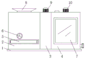
FIG. 1 is a schematic structural view of the present invention;
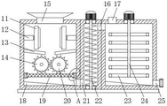
FIG. 2 is a schematic cross-sectional view of the present invention;
FIG. 3 is an enlarged schematic view of the structure at A of the present invention.
In the figure: 1. a base plate; 2. a crushing box; 3. a delivery box; 4. a stirring box; 5. a box door; 6. a first rotating electric machine; 7. an observation plate; 8. a flare tube; 9. a servo motor; 10. a second rotating electric machine; 11. rolling the plate; 12. a cylinder; 13. a first baffle; 14. a first crushing roller; 15. a feed pipe; 16. a discharge port; 17. a water inlet pipe; 18. a second baffle; 19. punching a screen plate; 20. a second crushing roller; 21. a feeding port; 22. a packing auger feeding mechanism; 23. a stirring blade; 24. a stirring rod; 25. a discharge pipe; 26. a card seat.
Detailed Description
The technical solutions in the embodiments of the present invention will be clearly and completely described below with reference to the drawings in the embodiments of the present invention, and it is obvious that the described embodiments are only a part of the embodiments of the present invention, and not all of the embodiments. All other embodiments, which can be derived by a person skilled in the art from the embodiments given herein without making any creative effort, shall fall within the protection scope of the present invention.
In the description of the present invention, it should be noted that the terms "upper", "lower", "inner", "outer", "front", "rear", "both ends", "one end", "the other end", and the like indicate orientations or positional relationships based on the orientations or positional relationships shown in the drawings, and are only for convenience of describing the present invention and simplifying the description, but do not indicate or imply that the referred device or element must have a specific orientation, be constructed in a specific orientation, and be operated, and thus, should not be construed as limiting the present invention. Furthermore, the terms "first" and "second" are used for descriptive purposes only and are not to be construed as indicating or implying relative importance.
In the description of the present invention, it is to be noted that, unless otherwise explicitly specified or limited, the terms "mounted", "provided", "connected", and the like are to be construed broadly, such as "connected", which may be fixedly connected, detachably connected, or integrally connected; can be mechanically or electrically connected; they may be connected directly or indirectly through intervening media, or they may be interconnected between two elements. The specific meanings of the above terms in the present invention can be understood in specific cases to those skilled in the art.
The bottom plate 1, the crushing box 2, the conveying box 3, the stirring box 4, the box door 5, the first rotating motor 6, the observation plate 7, the horn tube 8, the servo motor 9, the second rotating motor 10, the rolling plate 11, the cylinder 12, the first guide plate 13, the first crushing roller 14, the feeding pipe 15, the discharging port 16, the water inlet pipe 17, the second guide plate 18, the punching screen plate 19, the second crushing roller 20, the feeding port 21, the auger feeding mechanism 22, the stirring blades 23, the stirring rod 24, the discharging pipe 25 and the clamping seat 26 are all universal standard parts or parts known by technicians in the field, and the structure and the principle of the device can be known by technical manuals or conventional experimental methods.
Referring to fig. 1-3, an efficient recycled concrete production device for green building construction comprises a bottom plate 1, a crushing box 2 is fixedly connected to the left side of the top of the bottom plate 1, a feeding pipe 15 is communicated with the top of the crushing box 2, a horn tube 8 is communicated with the top of the feeding pipe 15, first guide plates 13 are obliquely arranged on the left side and the right side of the inner wall of the crushing box 2 and below a rolling plate 11, clamping seats 26 are fixedly connected to the bottoms of the left side and the right side of the inner wall of the crushing box 2, punching screen plates 19 are clamped in the inner cavities of the clamping seats 26, a conveying box 3 is fixedly connected to the middle end of the top of the bottom plate 1, a feeding port 21 is formed in the bottom of the right side of the crushing box 2 and the bottom of the left side of the conveying box 3, the crushing box 2 is communicated with the conveying box 3 through the feeding port 21, a discharging port 16 is formed in the top of the right side of the conveying box 3 and the top of the left side of a stirring box 4, and the conveying box 3 is communicated with the stirring box 4 through the discharging port 16, the top of the conveying box 3 is fixedly connected with a servo motor 9, the output end of the servo motor 9 penetrates into the inner cavity of the conveying box 3, the output end of the servo motor 9 is fixedly connected with a packing auger feeding mechanism 22, the right side of the top of the bottom plate 1 is fixedly connected with the stirring box 4, the bottom of the inner wall of the crushing box 2 and the bottom of the inner wall of the conveying box 3 are obliquely provided with a second guide plate 18, accumulation of raw materials is avoided by arranging a first guide plate 13 and the second guide plate 18, the bottom of the front surface of the crushing box 2 is movably connected with a box door 5 through a hinge, a clamping seat 26 and the box door 5 are arranged to facilitate the disassembly and the cleaning or the replacement of the punching screen plate 19, the front surface of the stirring box 4 is embedded with an observation plate 7, the stirring condition in the inner cavity of the stirring box 4 is conveniently checked by arranging the observation plate 7, the left side of the top of the stirring box 4 is communicated with a water inlet pipe 17, the bottom of the right side of the stirring box 4 is communicated with a discharging pipe 25, and the right side of the discharging pipe 25 is connected with a sealing cover by screw thread, the top parts of the left and right sides of the inner wall of the crushing box 2 are fixedly connected with an air cylinder 12, the output end of the air cylinder 12 is fixedly connected with a rolling plate 11, the left side of the front surface of the crushing box 2 is fixedly connected with a first rotating motor 6, the output end of the first rotating motor 6 penetrates into the inner cavity of the crushing box 2, and the surface of the output end of the first rotating motor 6 is fixedly connected with a first crushing roller 14, the inner cavity of the crushing box 2 and the right side of the first crushing roller 14 are movably connected with a second crushing roller 20 through a rotating shaft, the first crushing roller 14 is engaged with the second crushing roller 20 through crushing teeth, the top of the stirring box 4 is fixedly connected with a second rotating motor 10, the output end of the second rotating motor 10 is fixedly connected with a stirring rod 24, and the surface of the stirring rod 24 is fixedly connected with a plurality of stirring blades 23 which have the same size and are uniformly distributed.
When in use, the cylinder 12, the first rotating motor 6, the servo motor 9 and the second rotating motor 10 are controlled by the external controller, firstly, the output ends of the cylinders 12 on two sides extend inwards at the same time to drive the grinding plate 11 to move inwards to extrude and crush the recycled concrete raw material, then the output end of the first rotating motor 6 drives the first crushing roller 14 to rotate, the first crushing roller 14 drives the second crushing roller 20 to rotate under the meshing action of teeth, the recycled concrete raw material is crushed for the second time by the first crushing roller 14 and the second crushing roller 20, the crushed raw material is screened by the punching screen plate 19, the smaller raw material falls to the bottom of the inner cavity of the crushing box 2, the larger concrete is stopped at the top of the punching screen plate 19 to continue crushing, after the raw material at the bottom of the inner cavity of the crushing box 2 enters the inner cavity of the conveying box 3 through the feeding port 21, output through servo motor 9 drives auger feeding mechanism 22 and rotates, send into the inner chamber of agitator tank 4 through discharge gate 16 with the raw materials, the output through second rotation motor 10 at last drives puddler 24 and rotates, puddler 24 drives stirring vane 23 and rotates, carry out intensive mixing to recycled concrete raw materials, cooperation through above structure is used, it is not ideal to have solved current concrete mixing device work efficiency when using, thereby the problem that people use not convenient for (external control ware is the PLC controller in this application, simultaneously, two wiring ends of external control ware are connected with power plug through the wire, and adopt the commercial power to supply power in this application).
While embodiments of the present invention have been shown and described, it will be apparent to those skilled in the art that various modifications and changes may be made in the present invention. Any modification, equivalent replacement, improvement, etc. made within the spirit and principle of the present invention should be included in the scope of the claims of the present invention.
Claims (6)
1. The utility model provides a green is efficient recycled concrete apparatus for producing for construction, includes bottom plate (1), its characterized in that: the crushing device is characterized in that a crushing box (2) is fixedly connected to the left side of the top of the bottom plate (1), a conveying box (3) is fixedly connected to the middle end of the top of the bottom plate (1), a stirring box (4) is fixedly connected to the right side of the top of the bottom plate (1), air cylinders (12) are fixedly connected to the tops of the left side and the right side of the inner wall of the crushing box (2), a rolling plate (11) is fixedly connected to the output end of each air cylinder (12), a first rotating motor (6) is fixedly connected to the left side of the front surface of the crushing box (2), the output end of each first rotating motor (6) penetrates into the inner cavity of the crushing box (2), a first crushing roller (14) is fixedly connected to the surface of the output end of each first rotating motor (6), a second crushing roller (20) is movably connected to the right side of the inner cavity of the crushing box (2) through a rotating shaft, and the first crushing roller (14) and the second crushing roller (20) are meshed through crushing teeth, the top fixedly connected with second of agitator tank (4) rotates motor (10), the output fixedly connected with puddler (24) of motor (10) is rotated to the second, and the surperficial fixedly connected with a plurality of the same and evenly distributed stirring vane (23) of size of puddler (24).
2. The efficient recycled concrete production device for green building construction of claim 1, wherein: the top fixedly connected with servo motor (9) of transport case (3), the output of servo motor (9) runs through to the inner chamber of transport case (3) in, and the output fixedly connected with auger feeding mechanism (22) of servo motor (9).
3. The efficient recycled concrete production device for green building construction of claim 1, wherein: feed inlet (21) have all been seted up with the left bottom of delivery box (3) to the bottom on crushing case (2) right side, through feed inlet (21) intercommunication between crushing case (2) and delivery box (3), discharge gate (16) have all been seted up with the left top of agitator tank (4) to the top on delivery box (3) right side, and communicate through discharge gate (16) between delivery box (3) and agitator tank (4).
4. The efficient recycled concrete production device for green building construction of claim 1, wherein: the top intercommunication of smashing case (2) has inlet pipe (15), the top intercommunication of inlet pipe (15) has horn tube (8), the left and right sides of smashing case (2) inner wall and the below that is located rolling board (11) all incline and be provided with first guide plate (13), the equal fixedly connected with cassette (26) in bottom of the left and right sides of smashing case (2) inner wall, the inner chamber joint of cassette (26) has punching mesh board (19).
5. The efficient recycled concrete production device for green building construction of claim 1, wherein: the left side intercommunication at agitator tank (4) top has inlet tube (17), the bottom intercommunication on agitator tank (4) right side has discharging pipe (25), and the right side threaded connection of discharging pipe (25) has sealed lid.
6. The efficient recycled concrete production device for green building construction of claim 1, wherein: the bottom of smashing case (2) inner wall and the bottom of delivery box (3) inner wall all incline to be provided with second guide plate (18), there are chamber door (5) bottom through hinge swing joint smashing case (2) positive surface, the positive surface mosaic of agitator tank (4) has observation board (7).
Priority Applications (1)
| Application Number | Priority Date | Filing Date | Title |
|---|---|---|---|
| CN202122025345.0U CN216137279U (en) | 2021-08-26 | 2021-08-26 | Efficient recycled concrete apparatus for producing for green building construction |
Applications Claiming Priority (1)
| Application Number | Priority Date | Filing Date | Title |
|---|---|---|---|
| CN202122025345.0U CN216137279U (en) | 2021-08-26 | 2021-08-26 | Efficient recycled concrete apparatus for producing for green building construction |
Publications (1)
| Publication Number | Publication Date |
|---|---|
| CN216137279U true CN216137279U (en) | 2022-03-29 |
Family
ID=80808434
Family Applications (1)
| Application Number | Title | Priority Date | Filing Date |
|---|---|---|---|
| CN202122025345.0U Active CN216137279U (en) | 2021-08-26 | 2021-08-26 | Efficient recycled concrete apparatus for producing for green building construction |
Country Status (1)
| Country | Link |
|---|---|
| CN (1) | CN216137279U (en) |
Cited By (1)
| Publication number | Priority date | Publication date | Assignee | Title |
|---|---|---|---|---|
| CN116747760A (en) * | 2023-02-21 | 2023-09-15 | 广东恩美化工科技股份有限公司 | Automatic production equipment for printing ink production |
-
2021
- 2021-08-26 CN CN202122025345.0U patent/CN216137279U/en active Active
Cited By (1)
| Publication number | Priority date | Publication date | Assignee | Title |
|---|---|---|---|---|
| CN116747760A (en) * | 2023-02-21 | 2023-09-15 | 广东恩美化工科技股份有限公司 | Automatic production equipment for printing ink production |
Similar Documents
| Publication | Publication Date | Title |
|---|---|---|
| CN213434827U (en) | Novel production of root of kudzu vine powder is with smashing device | |
| CN209952946U (en) | Food production is with high-efficient making beating device | |
| CN216137279U (en) | Efficient recycled concrete apparatus for producing for green building construction | |
| CN213078596U (en) | Civil engineering construction waste treatment device | |
| CN218700454U (en) | Degradable tableware production and processing raw materials reducing mechanism | |
| CN217940287U (en) | Broken conveyor of refractory material | |
| CN218048108U (en) | Glossy ganoderma spore powder processing is with broken wall device | |
| CN216440828U (en) | Breaker is used in concrete production | |
| CN213315187U (en) | Multifunctional stirring and crushing equipment for engineering | |
| CN209093554U (en) | Pulverizer is used in a kind of production of bone meal | |
| CN210964816U (en) | Slurry mixing device capable of discharging quantitatively for artistic ceramic production | |
| CN211171387U (en) | Straw slurrying device | |
| CN220405783U (en) | Building solid waste processing apparatus | |
| CN211514718U (en) | Inorganic solid waste handles and uses compressor arrangement | |
| CN218422976U (en) | Slag treatment device for hydrofluoric acid production | |
| CN212396627U (en) | High-efficient mixing arrangement is used in intermediate production of medicine | |
| CN219903521U (en) | Feeder of powder cake tablet press | |
| CN217670509U (en) | Plastic processing machine capable of avoiding inlet blockage | |
| CN219744959U (en) | Biological feed reducing mechanism | |
| CN215464026U (en) | Multifunctional food processing stirring device | |
| CN215694248U (en) | Efficient linseed multistage reducing mechanism | |
| CN215311553U (en) | Processing raw material mixing device for observation window screen of washing machine | |
| CN212498420U (en) | Raw material mixing device for wood-plastic production | |
| CN219898408U (en) | Multistage reducing mechanism | |
| CN216821697U (en) | A high-efficient rubbing crusher for feed production |
Legal Events
| Date | Code | Title | Description |
|---|---|---|---|
| GR01 | Patent grant | ||
| GR01 | Patent grant | ||
| TR01 | Transfer of patent right | ||
| TR01 | Transfer of patent right |
Effective date of registration: 20220829 Address after: No. 1 Daying Hardware Building Materials Industrial Park, Daying Sub-district Office, Fumin County, Kunming City, Yunnan Province, 650000 Patentee after: Kunming Zhongchen New Building Materials Co.,Ltd. Address before: 743099 Hi Tech Department 1515, floor 15, innovation building, No. 21, Longxi Road, Anding District, Dingxi City, Gansu Province Patentee before: Shi Wanpeng |