CN216102387U - Automobile front cross beam and auxiliary frame and automobile using same - Google Patents
Automobile front cross beam and auxiliary frame and automobile using same Download PDFInfo
- Publication number
- CN216102387U CN216102387U CN202122912629.1U CN202122912629U CN216102387U CN 216102387 U CN216102387 U CN 216102387U CN 202122912629 U CN202122912629 U CN 202122912629U CN 216102387 U CN216102387 U CN 216102387U
- Authority
- CN
- China
- Prior art keywords
- front cross
- cover plate
- cross beam
- upper cover
- connecting section
- Prior art date
- Legal status (The legal status is an assumption and is not a legal conclusion. Google has not performed a legal analysis and makes no representation as to the accuracy of the status listed.)
- Active
Links
Images


Abstract
The utility model provides an automobile front cross beam, which comprises: a front beam connecting section; the head end of the front beam; the head end of the front cross beam and the tail end of the front cross beam are respectively positioned at two ends of the front cross beam connecting section; the cross section of the front cross beam connecting section is in a shape like a Chinese character ji, and the longitudinal sections of the head end of the front cross beam and the tail end of the front cross beam are in arc shapes. The utility model has better bending resistance and can increase the stability of the auxiliary frame structure of the automobile.
Description
Technical Field
The utility model relates to the field of automobiles, in particular to an automobile front cross beam, an auxiliary frame applied to the automobile front cross beam and an automobile.
Background
In the field of automotive applications, the safety performance of automotive collisions is receiving a great deal of attention, and automotive collisions are generally classified into frontal/side/rear collisions, as well as pedestrian collisions and vehicle rollover situations. The front collision accident has the highest occurrence proportion and the highest casualty rate, and particularly the occurrence probability of the vehicle-to-vehicle collision accident is higher, so that how to ensure the safety of passengers in the front collision accident, particularly the vehicle-to-vehicle accident, is a big problem for the current vehicle industry.
Among them, the cross section of the conventional front cross member is substantially square, and the area of the cross section is substantially uniform, so that it is difficult to satisfy the production requirements in terms of strength and rigidity when the front cross member is coupled with other members, and there is a need for improvement.
SUMMERY OF THE UTILITY MODEL
In order to solve the problem that the strength cannot meet the production requirement when the front cross beam is matched with other parts, the utility model provides an automobile front cross beam and an auxiliary frame and an automobile applied to the automobile front cross beam, and particularly provides the following technical scheme:
a front cross member for a vehicle, comprising:
a front beam connecting section;
the head end of the front beam; and
the head end of the front cross beam and the tail end of the front cross beam are respectively positioned at two ends of the front cross beam connecting section;
the cross section of the front cross beam connecting section is in a shape like a Chinese character ji, and the longitudinal sections of the head end of the front cross beam and the tail end of the front cross beam are in arc shapes.
In an embodiment of the present invention, the front beam head end and the front beam tail end are respectively located on a virtual horn face.
In an embodiment of the present invention, the front beam connecting section is provided with a front beam hole.
The utility model also provides an auxiliary frame applying the automobile front cross beam, which comprises the following components:
the tail ends of the two longitudinal beams are connected with a baffle; and
at least one vehicle front cross member, comprising:
a front beam connecting section;
the head end of the front beam; and
the head end of the front cross beam and the tail end of the front cross beam are respectively positioned at two ends of the front cross beam connecting section;
the cross section of the front cross beam connecting section is in a shape like a Chinese character ji, and the longitudinal sections of the head end of the front cross beam and the tail end of the front cross beam are in arc shapes;
and the two longitudinal beams are respectively connected with two ends of the front cross beam of the automobile through the baffle plates.
In an embodiment of the utility model, the longitudinal beam comprises an upper cover plate and a lower cover plate, wherein one opposite surface of the upper cover plate and the lower cover plate is recessed inwards to form a cavity, and the longitudinal sectional area of the outer contour formed by the upper cover plate and the lower cover plate is gradually reduced from one end to the other end.
In an embodiment of the present invention, the upper cover plate includes an upper cover plate head end, an upper cover plate tail end, and an upper cover plate connecting section, which connects the upper cover plate head end and the upper cover plate tail end.
In an embodiment of the present invention, the upper cover plate connection section is in an arc shape.
In an embodiment of the present invention, a stiffener is connected between the upper cover plate and the lower cover plate, and the stiffener is perpendicular to the upper cover plate and the lower cover plate.
In an embodiment of the present invention, the subframe further includes a mounting bracket connected to the upper cover plate.
The utility model also provides an automobile applying the automobile front cross beam, which comprises the following components:
an automobile body; and
at least one subframe, comprising:
at least two stringers; and
at least one vehicle front cross member, comprising:
a front beam connecting section;
the head end of the front beam; and
the head end of the front cross beam and the tail end of the front cross beam are respectively positioned at two ends of the front cross beam connecting section;
the cross section of the front cross beam connecting section is in a shape like a Chinese character ji, and the longitudinal sections of the head end of the front cross beam and the tail end of the front cross beam are in arc shapes;
the two longitudinal beams are respectively connected with two ends of the automobile front cross beam;
wherein, the sub vehicle frame is arranged in the automobile body.
The utility model provides an automobile front cross beam and an auxiliary frame and an automobile applying the same. The shape of the head end of the front beam and the shape of the tail end of the front beam are set to be horn-shaped, so that the mounting areas of the two ends of the front beam are increased, and the stability of the auxiliary frame structure of the automobile is further realized.
Drawings
FIG. 1 is a front cross member elevational view of the present invention;
FIG. 2 is a right side view of the front cross member of the present invention;
FIG. 3 is a schematic view of the cross section along AA in FIG. 1;
FIG. 4 is a front view of the subframe of the present invention;
FIG. 5 is a right side view of the subframe of the present invention;
FIG. 6 is a top view of the subframe of the present invention;
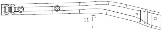
FIG. 7 is a front view of an upper deck of the stringer of the present invention;
FIG. 8 is a top plan view of the upper deck of the stringer of the present invention;
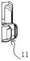
FIG. 9 is a left side view of the upper deck of the stringer of the present invention;
FIG. 10 is a schematic view of an upper deck structure of another stringer of the present invention;
FIG. 11 is a front view of the lower deck of the stringer of the present invention;
FIG. 12 is a top plan view of the lower deck of the stringer of the present invention;
FIG. 13 is a left side view of the lower deck of the stringer of the present invention;
FIG. 14 is a schematic view of the construction of the lower deck of another stringer of the present invention;
FIG. 15 is a front view of the mounting bracket of the present invention;
FIG. 16 is a left side view of the mounting bracket of the present invention;
FIG. 17 is a top view of the mounting bracket of the present invention;
FIG. 18 is a schematic view of a stiffener structure according to the present invention;
FIG. 19 is a front view of the attachment bracket of the present invention;
FIG. 20 is a top view of the attachment bracket of the present invention;
FIG. 21 is a left side view of the attachment bracket of the present invention;
FIG. 22 is a schematic view of an automobile according to the present invention;
in the figure: 1. an auxiliary frame; 11. an upper cover plate; 111. the head end of the upper cover plate; 112. reinforcing ribs; 113. an upper cover plate connecting section; 114. the end of the upper cover plate; 12. a lower cover plate; 121. the head end of the lower cover plate; 122. reinforcing rib slotted holes; 123. a lower cover plate connecting section; 124. the end of the lower cover plate; 13. mounting a bracket; 131. mounting a bracket bulge; 132. mounting a bracket bottom plate; 133. installing a bracket hole; 14. a reinforcing plate; 141. the head end of the reinforcing plate; 142. a reinforcing plate connecting section; 143. a stiffener tail end; 144. a stiffener plate hole; 15. a baffle plate; 2. a stringer; 3. a front cross member; 31. the head end of the front beam; 32. the tail end of the front cross beam; 33. a front beam connecting section; 34. a front beam hole; 4. connecting a bracket; 41. a bolt; 42. connecting the head end of the bracket; 43. connecting the bracket connecting sections; 44. connecting the tail ends of the brackets; 5. an automobile body.
Detailed Description
The embodiments of the present invention are described below with reference to specific embodiments, and other advantages and effects of the present invention will be easily understood by those skilled in the art from the disclosure of the present specification. The utility model is capable of other and different embodiments and of being practiced or of being carried out in various ways, and its several details are capable of modification in various respects, all without departing from the spirit and scope of the present invention.
It should be noted that the drawings provided in the present embodiment are only for illustrating the basic idea of the present invention, and the components related to the present invention are only shown in the drawings rather than drawn according to the number, shape and size of the components in actual implementation, and the type, quantity and proportion of the components in actual implementation may be changed freely, and the layout of the components may be more complicated.
Referring to fig. 1 to 3, the present invention provides a front cross member of an automobile, in some embodiments, the specific structure of the front cross member 3 is not limited, in some embodiments, the front cross member 3 may include a front cross member head end 31, a front cross member tail end 32, and a front cross member connection section 33, and the front cross member connection section 33 may be used to connect the front cross member head end 31 and the front cross member tail end 32. The specific structures of the front beam head end 31, the front beam tail end 32 and the front beam connecting section 33 are not limited, in some embodiments, the front beam head end 31 and the front beam tail end 32 may be bent toward the same side along the front beam connecting section 33, and the longitudinal sections of the front beam head end 31 and the front beam tail end 32 may be in an arc shape or an exponential curve shape, so that the contact area between the front beam 3 and the longitudinal beam 2 may be increased. In some embodiments, the front beam head end 31 and the front beam tail end 32 may be respectively located on a virtual horn surface, and the front beam head end 31 and the front beam tail end 32 are shaped into a horn shape, so that the installation area of the two ends of the front beam 3 is increased, and further the stability of the auxiliary frame structure of the automobile is realized. The cross section of the front beam connecting section 33 can be in a shape like a Chinese character 'ji', and has better bending resistance. The front beam connecting section 33 may be formed with a front beam hole 34, the front beam hole 34 may be used to provide an installation position of the engine, the specific shape of the front beam hole 34 is not limited, and in some embodiments, the front beam hole 34 may be a circular shape or a rectangular shape, for example, the front beam hole 34 may be a circular shape.
Referring to fig. 4 to 6, in some embodiments, the present invention provides a subframe using a longitudinal beam of an automobile, where the subframe 1 may include a front cross beam 3; and at least two automobile longitudinal beams 2, the longitudinal beams 2 may include: an upper cover plate 11; the opposite surfaces of the upper cover plate 11 and the lower cover plate 12 can be inwards recessed to form a cavity, and the longitudinal sectional area of the outer contour formed by the upper cover plate 11 and the lower cover plate 12 from one end to the other end can be gradually reduced; the two automobile longitudinal beams 2 can be respectively connected with two ends of the front cross beam 3.
Referring to fig. 7 to 14, in some embodiments, the longitudinal beam 2 may include an upper cover plate 11 and a lower cover plate 12, the upper cover plate 11 and the lower cover plate 12 are connected together in a matching manner, in some embodiments, the facing surfaces of the upper cover plate 11 and the lower cover plate 12 may be recessed inwards to form a cavity, and the cavity inside the longitudinal beam 2 is provided with a benefit that reinforcing members such as reinforcing ribs or reinforcing plates 14 may be provided inside the longitudinal beam 2, so that the overall strength of the structure of the longitudinal beam 2 may be further improved. The specific shape of the outer contour formed by the upper cover plate 11 and the lower cover plate 12 is not limited, and in some embodiments, the outer contour formed by connecting the upper cover plate 11 and the lower cover plate 12 may be in the shape of a cylinder, a rectangular parallelepiped, an elliptic cylinder, and the like, for example, the outer contour formed by the upper cover plate 11 and the lower cover plate 12 may gradually decrease the longitudinal sectional area from one end to the other end, and the advantage of setting the longitudinal sectional area of the upper cover plate 11 and the lower cover plate 12 to gradually decrease is that the stress conditions of different longitudinal sections of the upper cover plate 11 and the lower cover plate 12 are different, which is beneficial to improving the stress and support conditions of the upper cover plate 11 and the lower cover plate 12, i.e., enhancing the stress and support conditions of the longitudinal beam 2.
Referring to fig. 7 to 14, in some embodiments, the upper cover plate 11 may include an upper cover plate head end 111, an upper cover plate connecting section 113 and an upper cover plate tail end 114, wherein the upper cover plate connecting section 113 may be used to connect the upper cover plate head end 111 and the upper cover plate tail end 114. The specific shape of the upper cover plate head end 111, the upper cover plate connecting section 113 and the upper cover plate tail end 114 is not limited, and in some embodiments, the longitudinal cross-sectional area of the upper cover plate head end 111 may be the smallest, the longitudinal cross-sectional area of the upper cover plate tail end 114 may be the largest, and the upper cover plate connecting section 113 may have an arc shape. The lower cover plate 12 is adapted to the upper cover plate 11, the lower cover plate 12 may include a lower cover plate head end 121, a lower cover plate connecting section 123 and a lower cover plate tail end 124, and the lower cover plate connecting section 123 may be used to connect the lower cover plate head end 121 and the lower cover plate tail end 124. The longitudinal cross-sectional area of the head end 121 of the lower cover plate may be the smallest, the longitudinal cross-sectional area of the tail end 124 of the lower cover plate may be the largest, and the lower cover plate connection section 123 may have an arc shape. Wherein, can be provided with strengthening rib 112 between upper cover plate 11 and the lower cover plate 12, the concrete mounted position of strengthening rib 112 does not put the restriction, and strengthening rib 112 can be installed on upper cover plate 11, and with this adaptation, can open on the lower cover plate 12 and be equipped with strengthening rib slotted hole 122, and strengthening rib 112 can be with strengthening rib slotted hole 122 looks adaptation. The specific location of the ribs 112 is not limited, and in some embodiments, the ribs 112 can be perpendicular to the upper and lower cover plates 11, 12.
Referring to fig. 12 and 13, in some embodiments, the longitudinal beam 2 may be provided with a baffle 15, the baffle 15 may be located at one end of the longitudinal beam 2, the baffle 15 may increase the cross-sectional area of the front end of the longitudinal beam 2, and the longitudinal beam 2 may be connected to the front cross beam 3 through the baffle 15. Therefore, in the collision process, the contact area between the side beam 2 and the barrier and between the side beam and the vehicle on the other side is increased, the bending stability of the side beam is provided after the contact area is increased, and the purposes of dispersing collision load and absorbing energy are achieved. The connection mode between the baffle 15 and the longitudinal beam 2 is not limited, and in some embodiments, the baffle 15 and the longitudinal beam 2 can be welded or bolted, so that the installation is convenient and the cost is low.
Referring to fig. 14 and 18, in some embodiments, the inner portion of the longitudinal beam 2 may be provided with a reinforcing plate 14, and the specific position of the reinforcing plate 14 is not limited, and in some embodiments, the reinforcing plate 14 may be parallel to the upper cover plate 11 and the lower cover plate 12. The specific structure of the stiffener 14 is not limited, and in some embodiments, the stiffener 14 may include a stiffener head end 141, a stiffener connecting section 142, and a stiffener tail end 143, and the stiffener connecting section 142 may be used to connect the stiffener head end 141 and the stiffener tail end 143, wherein the stiffener connecting section 142 may have a circular arc shape. The reinforcing plate head end 141 can be adapted to the upper cover plate head end 111, the reinforcing plate connecting section 142 can be adapted to the upper cover plate connecting section 113, and the reinforcing plate tail end 143 can be adapted to the upper cover plate tail end 114. The stiffener 14 may be formed with stiffener holes 144, and the specific shape of the stiffener holes 144 is not limited, and in some embodiments, the stiffener holes 144 may be rectangular, circular, oval, etc., for example, the stiffener holes 144 may be circular.
Referring to fig. 6 and 15 to 17, in some embodiments, the longitudinal beam 2 may be provided with a mounting bracket 13, the mounting bracket 13 may be mounted on the upper cover plate 11, the mounting bracket 13 may include a mounting bracket protrusion 131, a mounting bracket bottom plate 132 and a mounting bracket hole 133, two sides of the mounting bracket bottom plate 132 may be provided with the mounting bracket protrusion 131 protruding upward, the mounting bracket bottom plate 132 may be provided with the mounting bracket hole 133, and the mounting bracket hole 133 may be circular. The mounting bracket 13 is arranged to provide a connection location for the side member 2, i.e. a mounting location for the subframe 1.
Referring to fig. 22, in some embodiments, the present invention provides an automobile using a longitudinal beam, which may include: an automobile body 5; and at least one subframe 1, the subframe 1 may comprise: a front cross member 3; and at least two automobile longitudinal beams 2, the longitudinal beams 2 may include: an upper cover plate 11; the opposite surfaces of the upper cover plate 11 and the lower cover plate 12 are inwards recessed to form a cavity, and the longitudinal sectional area of the outer contour formed by the upper cover plate 11 and the lower cover plate 12 is gradually reduced from one end to the other end; the two automobile longitudinal beams 2 are respectively connected with two ends of the front cross beam 3; the subframe 1 may be disposed in the vehicle body 5.
Referring to fig. 19 to 21, in some embodiments, an automobile using automobile longitudinal beams may further include a connecting bracket 4, where the connecting bracket 4 may include a bolt 41, a connecting bracket head end 42, a connecting bracket connecting section 43, and a connecting bracket tail end 44, where the connecting bracket connecting section 43 may be used to connect the connecting bracket head end 42 and the connecting bracket tail end 44, and the connecting bracket connecting section 43 may be in a groove shape. One end of the connecting bracket 4 can be connected with the longitudinal beam 2, and the other end of the connecting bracket 4 can be connected with the automobile main body 5.
The above description is only a preferred embodiment of the present application and the explanation of the applied technical principle, and it should be understood by those skilled in the art that the scope of the present application is not limited to the technical solution of the specific combination of the above technical features, and also covers other technical solutions formed by any combination of the above technical features or their equivalent features without departing from the inventive concept, for example, the technical solutions formed by mutually replacing the above technical features (but not limited to) having similar functions disclosed in the present application.
Other technical features than those described in the specification are known to those skilled in the art, and are not described herein in detail in order to highlight the innovative features of the present invention.
Claims (10)
1. A front cross member for a vehicle, comprising:
a front beam connecting section;
the head end of the front beam; and
the head end of the front cross beam and the tail end of the front cross beam are respectively positioned at two ends of the front cross beam connecting section;
the cross section of the front cross beam connecting section is in a shape like a Chinese character ji, and the longitudinal sections of the head end of the front cross beam and the tail end of the front cross beam are in arc shapes.
2. The vehicle front cross member of claim 1, wherein the front cross member head end and the front cross member tail end are each located on an imaginary horn face.
3. The automobile front cross beam of claim 1, wherein the front cross beam connecting section is provided with a front cross beam hole.
4. The utility model provides an use sub vehicle frame of car front beam which characterized in that, it includes:
the tail ends of the two longitudinal beams are connected with a baffle; and
at least one vehicle front cross member, comprising:
a front beam connecting section;
the head end of the front beam; and
the head end of the front cross beam and the tail end of the front cross beam are respectively positioned at two ends of the front cross beam connecting section;
the cross section of the front cross beam connecting section is in a shape like a Chinese character ji, and the longitudinal sections of the head end of the front cross beam and the tail end of the front cross beam are in arc shapes;
and the two longitudinal beams are respectively connected with two ends of the front cross beam of the automobile through the baffle plates.
5. The subframe of claim 4 wherein said longitudinal member comprises:
an upper cover plate; and
the outer contour of the upper cover plate and the outer contour of the lower cover plate are gradually reduced from one end to the other end.
6. The subframe of claim 5, wherein said top cover plate comprises:
the head end of the upper cover plate;
the end of the upper cover plate; and
and the upper cover plate connecting section is connected with the head end of the upper cover plate and the tail end of the upper cover plate.
7. The subframe of claim 6 wherein said upper cover plate connecting section is arcuate in shape.
8. The subframe according to claim 5, wherein a reinforcing rib is connected between the upper cover plate and the lower cover plate, and the reinforcing rib is perpendicular to the upper cover plate and the lower cover plate.
9. The subframe for applying a front cross member of a vehicle as claimed in claim 5, further comprising:
and the mounting bracket is connected to the upper cover plate.
10. An automobile using a front cross member of the automobile, characterized by comprising:
an automobile body; and
at least one subframe, comprising:
at least two stringers; and
at least one vehicle front cross member, comprising:
a front beam connecting section;
the head end of the front beam; and
the head end of the front cross beam and the tail end of the front cross beam are respectively positioned at two ends of the front cross beam connecting section;
the cross section of the front cross beam connecting section is in a shape like a Chinese character ji, and the longitudinal sections of the head end of the front cross beam and the tail end of the front cross beam are in arc shapes;
the two longitudinal beams are respectively connected with two ends of the automobile front cross beam;
wherein, the sub vehicle frame is arranged in the automobile body.
Priority Applications (1)
| Application Number | Priority Date | Filing Date | Title |
|---|---|---|---|
| CN202122912629.1U CN216102387U (en) | 2021-11-25 | 2021-11-25 | Automobile front cross beam and auxiliary frame and automobile using same |
Applications Claiming Priority (1)
| Application Number | Priority Date | Filing Date | Title |
|---|---|---|---|
| CN202122912629.1U CN216102387U (en) | 2021-11-25 | 2021-11-25 | Automobile front cross beam and auxiliary frame and automobile using same |
Publications (1)
| Publication Number | Publication Date |
|---|---|
| CN216102387U true CN216102387U (en) | 2022-03-22 |
Family
ID=80718753
Family Applications (1)
| Application Number | Title | Priority Date | Filing Date |
|---|---|---|---|
| CN202122912629.1U Active CN216102387U (en) | 2021-11-25 | 2021-11-25 | Automobile front cross beam and auxiliary frame and automobile using same |
Country Status (1)
| Country | Link |
|---|---|
| CN (1) | CN216102387U (en) |
-
2021
- 2021-11-25 CN CN202122912629.1U patent/CN216102387U/en active Active
Similar Documents
| Publication | Publication Date | Title |
|---|---|---|
| CN109987140B (en) | Automobile frame | |
| CN207826349U (en) | Automobile front wall structure and body of a motor car | |
| CN210882348U (en) | Threshold beam for electric automobile | |
| CN213862434U (en) | Threshold roof beam and car floor structure | |
| CN211617879U (en) | Vehicle body assembly and vehicle with same | |
| CN216102387U (en) | Automobile front cross beam and auxiliary frame and automobile using same | |
| CN216269525U (en) | Automobile longitudinal beam and auxiliary frame and automobile applying same | |
| CN217022691U (en) | Automobile threshold assembly | |
| CN104477240A (en) | Front vertical beam reinforcing plate, right front vertical beam and automobile | |
| CN212500670U (en) | Vehicle body structure and automobile | |
| CN211167095U (en) | Vehicle beam assembly and frame | |
| CN217170621U (en) | Rear lower protection device for vehicle and vehicle with same | |
| CN218536898U (en) | Well floor structure assembly and vehicle | |
| CN220430307U (en) | Vehicle body structure and vehicle | |
| CN217533004U (en) | Cover inner plate, preceding cover and car of car | |
| CN213384465U (en) | Vehicle body rear floor | |
| CN115107490B (en) | Battery pack mounting structure and car | |
| CN217649541U (en) | Reinforcing plate structure of vehicle and vehicle | |
| CN220180935U (en) | Front longitudinal beam assembly and automobile body | |
| CN218021513U (en) | Preceding crashproof roof beam assembly and car | |
| CN219339564U (en) | Threshold assembly and vehicle | |
| CN216734491U (en) | Front fingerboard assembly and vehicle with same | |
| CN218400717U (en) | Supporting and protecting beam of automobile | |
| CN220374635U (en) | Automobile top cover and automobile with same | |
| CN215883814U (en) | Front longitudinal beam avoiding and reinforcing combined structure |
Legal Events
| Date | Code | Title | Description |
|---|---|---|---|
| GR01 | Patent grant | ||
| GR01 | Patent grant | ||
| TR01 | Transfer of patent right |
Effective date of registration: 20220328 Address after: 310000 1760 Jiangling Road, Binjiang District, Hangzhou, Zhejiang. Patentee after: ZHEJIANG GEELY HOLDING GROUP Co.,Ltd. Patentee after: Zhejiang liankong Technology Co., Ltd Address before: 310000 1760 Jiangling Road, Binjiang District, Hangzhou, Zhejiang. Patentee before: ZHEJIANG GEELY HOLDING GROUP Co.,Ltd. Patentee before: Geely Automobile Research Institute (Ningbo) Co., Ltd |
|
| TR01 | Transfer of patent right |