CN216078416U - Multifunctional water tap with rotatable water outlet - Google Patents
Multifunctional water tap with rotatable water outlet Download PDFInfo
- Publication number
- CN216078416U CN216078416U CN202122638763.7U CN202122638763U CN216078416U CN 216078416 U CN216078416 U CN 216078416U CN 202122638763 U CN202122638763 U CN 202122638763U CN 216078416 U CN216078416 U CN 216078416U
- Authority
- CN
- China
- Prior art keywords
- water
- filter element
- valve seat
- mixed
- gland
- Prior art date
- Legal status (The legal status is an assumption and is not a legal conclusion. Google has not performed a legal analysis and makes no representation as to the accuracy of the status listed.)
- Active
Links
Images


Landscapes
- Multiple-Way Valves (AREA)
Abstract
The utility model provides a multifunctional water tap with a rotatable water outlet, which comprises a tap body (1), a valve seat (2), a water distribution component (3) and a filter element (4), wherein the water distribution component (3) comprises a sleeve part (34) and an extension part (35), the inner wall of the upper end of the sleeve part (34) is provided with a mixed water inlet (32) and a purified water inlet (33) which are respectively connected with a mixed water pipeline (314) and a purified water pipeline (313) in the extension part (35); the water diversion component (3) is arranged on the valve seat (2), and a space enclosed between the outer wall of the filter element shell (41) and the inner wall of the water diversion component (3) is a mixed water passage (31). The faucet has a simple structure, can realize the respective use of tap water and water produced by the filter element, and has a rotatable water outlet, so that the faucet is more convenient to use.
Description
[ technical field ] A method for producing a semiconductor device
The utility model relates to a multifunctional water faucet, in particular to a multifunctional water faucet with a built-in water purification filter element and a rotatable water outlet.
[ background of the utility model ]
Along with the improvement of living standard, people attach more and more importance to drinking water safety, and for using the healthy drinking water of quality of water, many families choose to install the water purifier or install filter equipment additional at tap outside and carry out the water purification. The water purifier is of a great variety and the design occupation space is big in the existing market, the filter element is inconvenient to install and dismantle, and a water outlet faucet is usually required to be installed independently, so that the product occupation space is large, and the user is inconvenient to use raw water and clean water.
The utility model provides a multifunctional water tap with a rotatable water outlet, which is disclosed by the Chinese utility model patent CN 210716117U, and comprises a tap main body shell, a valve seat and a filter element, wherein a rotating shaft water separator and a water outlet tap fixedly connected with the rotating shaft water separator are arranged on the upper part of the tap main body shell. The tap part of the multifunctional water tap can rotate 360 degrees. However, the present inventors believe that the multi-functional faucets can continue to improve and have achieved better product durability.
[ Utility model ] content
The utility model aims to overcome the defects of the prior art and provides a multifunctional water faucet with a rotatable water outlet, which has a simpler structure and smoother hand feeling of a user during rotation.
In order to achieve the above purpose, the present invention provides a multifunctional faucet with a rotatable water outlet, the faucet comprises a faucet body 1, a valve seat 2 arranged in the faucet body 1 and a water diversion component 3 arranged in the valve seat 2, a filter element 4 is arranged in the water diversion component 3, the filter element 4 is provided with a filter element shell 41, a filter element water inlet end 42 positioned at the bottom and a filter element water production end 43 positioned at the top, and a filter element gland 5 is arranged at the top of the filter element 4; the valve seat 2 is internally provided with a cold water passage 21 and a hot water passage 22, the upper part of the valve seat 2 is provided with a valve seat mixing water port 23 and a valve seat cold water port 24, the cold water passage 21 is connected with a municipal tap water outlet end and the valve seat cold water port 24, the cold water passage 21 is also connected with the municipal tap water outlet end and the valve seat mixing water port 23 through a branch, and the hot water passage 22 is connected with the municipal hot water outlet end and the valve seat mixing water port 23; the upper part of the valve seat 2 is also provided with a component slot 25;
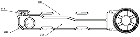
wherein, the water diversion component 3 comprises a hollow sleeve part 34 and an extension part 35 positioned at the upper end of the sleeve part 34, the bottom of the sleeve part 34 is a component socket 36 matched with the component slot 25, the inner wall of the upper end of the sleeve part 34 is provided with a mixed water inlet 32 and a purified water inlet 33, and the level of the mixed water inlet 32 in the sleeve part 34 is lower than that of the purified water inlet 33 in the sleeve part 34; a purified water pipeline 313 and a mixed water pipeline 314 are arranged in the extension part 35, a first water outlet 311 and a second water outlet 312 are arranged at the far end of the extension part 35, one end of the purified water pipeline 313 is connected with the second water outlet 312, the other end of the purified water pipeline is connected with the purified water inlet 33, one end of the mixed water pipeline 314 is connected with the first water outlet 311, and the other end of the mixed water pipeline 314 is connected with the mixed water inlet 32;
a gland water purification passage 53 is arranged in the filter element gland 5, a mixed water sealing ring 51 and a water purification sealing ring 52 are arranged on the outer side of the filter element gland 5, the level of the mixed water sealing ring 51 in the filter element gland 5 is lower than that of the gland water purification passage 53, and the level of the water purification sealing ring 52 in the filter element gland 5 is higher than that of the gland water purification passage 53;
in an assembly state, the water diversion component 3 is arranged on the valve seat 2 through the component slot 25 of the valve seat 2 and the component socket 36 of the water diversion component 3, the filter element 4 is arranged in the water diversion component 3, the water inlet end 42 of the filter element is connected with the cold water port 24 of the valve seat at the moment, a space enclosed between the outer wall of the filter element shell 41 and the inner wall of the water diversion component 3 is a mixed water passage 31, the lower end of the mixed water passage 31 is connected with the mixed water port 23 of the valve seat, and the upper end of the mixed water passage 31 is connected with the mixed water inlet 32;
install filter core gland 5 in filter core 4 upper portion, the level of mixed water sealing washer 51 is in between mixed water inlet 32 and pure water inlet 33 this moment, keeps apart mixed water inlet 32 and pure water inlet 33 through mixed water sealing washer 51, and mixed water access 31 communicates with mixed water inlet 32 this moment, and gland pure water access 53 communicates filter core product water end 43 and pure water inlet 33.
In the present invention, for convenience of description and not limitation, the term "upper" refers to a direction toward the decorative cover 10 in an assembled state, such as "upper end" and "upper portion", and the term "lower" is opposite thereto.
In the present invention, the valve seat 2 is used for realizing that the outlet water of municipal tap water (including a cold water end and a hot water end) is correctly distributed to each waterway. Generally, the cold water end is distributed to the filter element inlet water and the cold and hot mixed water through different water paths, the hot water end is distributed to the cold and hot mixed water through the water paths, and the opening and closing of each water path are realized through the matching of a tap water valve core in the valve seat 2 and a water purifying valve core. Therefore, a user can select to obtain cold and pure water through the water purification filter element or obtain cold tap water, hot tap water or cold and hot mixed tap water without the water purification filter element by controlling the faucet. The skilled person will be able to select an appropriate valve seat, valve element or corresponding fitting to implement the solution of the valve seat 2 of the present invention, according to the teachings of the prior art.
In the utility model, the multifunctional water tap further comprises a connecting cylinder 6 in threaded connection with the tap body 1, and the height of the upper end of the connecting cylinder 6 is flush with the height of the lower end surface of the extension part 35. In an assembly state, the faucet body 1 and the connecting cylinder 6 are connected through threads to form a whole shell, the water distribution component is inserted into the component slot 25, and the water distribution component 3 can rotate in the circle center of the building slot 25, namely the extension part 35 can rotate around the shaft, so that the rotation of the water outlet of the faucet is realized, because a limiting device is not arranged between the water distribution component 3 and the faucet body 1 or the connecting cylinder 6, and the cross sections of the component slot 25 and the component socket 36 are circular.
According to a preferred embodiment, a positioning ring 8 is arranged in the middle of the outer wall of the water dividing member 3 to ensure that the water dividing member 3 can be inserted into the tap body 1 at the correct insertion depth.
Furthermore, a lower friction ring 7 and an upper friction ring 9 are provided between the outer wall of the water dividing member 3 and the connecting cylinder 6. Since the water diversion member 3 and the connecting cylinder 6 are nested, in order to reduce friction damage between the water diversion member 3 and the connecting cylinder 6 and collision caused by slight deformation, a lower friction ring 7 and an upper friction ring 9 are respectively arranged on the outer wall of the water diversion member 3, and the horizontal heights thereof are respectively positioned at the lower part and the upper part of the connecting cylinder 6.
In the utility model, the multifunctional water faucet also comprises a tap water valve core and a water purification valve core which are respectively connected with the valve seat 2.
The multi-functional faucet further includes a finishing cap 10 provided at an upper portion of the cartridge cover 5 for the sake of aesthetic appearance of the product.
Preferably, the multifunctional faucet further comprises an electronic control display module. The electronic control display module generally comprises a display screen and an electronic control module, and the electronic control module is connected with a power supply. The detection or control of the faucet by selecting the electric control display module with a proper model is a technology which is known by technicians in the field, for example, the electric control module realizes the functions of displaying the service life reminding of the filter element on a display screen by counting down, and the like, and the detailed description is omitted here.
In the present invention, the first water outlet 311 and the second water outlet 312 are arranged in parallel.
In the utility model, the filter element 4 is an ultrafiltration composite filter element or an ultrafiltration filter element.
In order to ensure the installation and connection of the filter element gland 5 of the water diversion component 3, preferably, a slide rail is arranged on the inner side of the upper part of the water diversion component 3, and a gland clamping groove is arranged on the slide rail; the middle part of the outer side of the filter element gland is provided with a clamping point matched with the gland clamping groove, and the filter element gland 5 is mechanically connected with the water distribution component 3 by screwing the clamping point into the clamping groove along the direction of the slide rail.
When the water faucet is used, all the parts are installed in place, namely the water faucet body 1 and the connecting cylinders 6 are screwed, the filter element 4 is installed in the water distribution member 3, the water distribution member 3 is inserted into the valve seat 2 and can rotate around the shaft on the valve seat 2, the filter element 4 is pressed downwards by the filter element pressing cover 5, and finally the decorative cover 10 is arranged outside the filter element pressing cover 5.
When the cold tap water needs to be discharged, the tap water valve core arranged in the valve seat 2 is controlled to connect the cold water passage 21 with the mixed water passage 31, the valve seat hot water passage 22 is closed, the discharged water at the cold water end of the municipal tap water flows into the mixed water passage 31 through the cold water passage 21 of the valve seat 2, then enters the mixed water passage 314 from the mixed water inlet 32 at the upper part of the water diversion member 3, and finally flows out from the first water outlet 311. When the cold tap water passes through the mixed water inlet 32, since the mixed water inlet 32 is located at a lower level in the sleeve portion 34 than the clean water inlet 33 is located in the sleeve portion 34, and the mixed water packing 51 is located at a level between the mixed water inlet 32 and the clean water inlet 33, the mixed water inlet 32 and the clean water inlet 33 are isolated by the mixed water packing 51, so that the cold tap water in the mixed water passage 31 entirely enters the mixed water passage 314 through the mixed water inlet 32 without contacting the clean water inlet 33 or the capped clean water passage 53.
Similarly, when hot water is required to be discharged, the valve seat hot water passage 22 and the mixed water passage 31 are communicated by controlling the tap water valve core arranged in the valve seat 2, the cold water passage 21 is closed, and the discharged water at the hot water end of municipal tap water enters the mixed water passage 314 through the mixed water inlet 32 through the mixed water passage 31 and also flows out from the first water outlet 311.
Similarly, when warm water is required to be discharged, the valve seat hot water passage 22 and the mixed water passage 31 are connected, the cold water passage 21 and the mixed water passage 31 are also connected by controlling the tap water valve core arranged in the valve seat 2, and discharged water of the hot water end and the cold water end of municipal tap water passes through the mixed water passage 31, enters the mixed water passage 314 through the mixed water inlet 32 and also flows out of the first water outlet 311.
When purified water is required to be discharged, the cold water passage 21 is communicated with the water inlet end 42 of the filter element through the water purifying valve core arranged in the control valve seat 2, and municipal tap water enters the filter element 4 to be purified. The produced water of the filter element 4 flows out from the filter element water producing end 43 at the top of the filter element 4, fills in the gland water purifying passage 53, enters the water purifying water channel 313 through the water purifying water inlet 33, and finally flows out from the second water outlet 312. Similarly, when the produced water of the cartridge passes through the purified water inlet 33, since the purified water inlet 33 is located at a level higher than the level of the mixed water inlet 32 in the sleeve portion 34 and the level of the mixed water seal ring 51 is located between the mixed water inlet 32 and the purified water inlet 33, the mixed water inlet 32 and the purified water inlet 33 are isolated by the mixed water seal ring 51, and thus the produced water of the cartridge in the capped purified water passage 53 entirely enters the purified water passage 313 through the purified water inlet 33 without contacting the mixed water inlet 32 or the mixed water passage 31. Meanwhile, the water produced by the filter element is prevented from overflowing upwards and leaking through the water purifying sealing ring 52 arranged above the level height of the water purifying channel 53 of the gland.
The faucet has a simple structure, can realize the respective use of tap water and water produced by the filter element, and has a rotatable water outlet, so that the faucet is more convenient to use.
[ description of the drawings ]
FIG. 1 is a block diagram of the faucet of the present invention;
FIG. 2 is a perspective view of the water diversion mechanism;
FIG. 3 is a right side view of the water diversion mechanism;
FIG. 4 is a bottom view of the water diversion mechanism;
FIG. 5 is a perspective view of the filter element gland;
FIG. 6 is a front view of the cartridge cover;
FIG. 7 is a view of a valve seat structure;
fig. 8 is a top view of the valve seat.
Wherein:
1. a faucet body; 11. a faucet handle; 12. display screen
2. A valve seat; 21. a cold water passage; 22. a valve seat hot water passageway; 23. a valve seat mixing water gap; 24. a valve seat cold water port; 25. a component slot;
3. a water diversion member; 31. a mixed water passage; 32. a mixed water inlet; 33. a purified water inlet; 34. a sleeve portion; 35. an extension portion; 36. a component socket; 311. a first water outlet; 312. a second water outlet; 313. a purified water path; 314. a mixed water waterway;
4. a filter element; 41. a filter element housing; 42. a water inlet end of the filter element; 43. filter element water production end
5. A filter element gland bush; 51. mixing water sealing rings; 52. a clean water sealing ring; 53. a water purification passage is pressed;
6. a connecting cylinder; 7. a lower friction ring; 8. a positioning ring; 9. an upper friction ring; 10. and (6) a decorative cover.
[ detailed description ] embodiments
The following examples serve to illustrate the technical solution of the present invention without limiting it.
Example 1
The multifunctional water tap with the rotatable water outlet shown in figure 1 comprises a tap body 1; a connecting cylinder 6; a valve seat 2; a water diversion member 3; a filter element 4; a filter element pressing cover 5 and a decorative cover 10.
Tap body 1 and connecting cylinder 6 threaded connection, valve seat 2 installs in tap body 1.
As shown in fig. 7-8, the valve seat 2 is internally provided with a cold water passage 21 and a valve seat hot water passage 22, the upper part of the valve seat 2 is provided with a valve seat mixing water gap 23 and a valve seat cold water gap 24, the cold water passage 21 is connected with a municipal tap water outlet end and the valve seat cold water gap 24, the cold water passage 21 is also connected with the municipal tap water outlet end and the valve seat mixing water gap 23 through a branch, and the hot water passage 22 is connected with the municipal hot water outlet end and the valve seat mixing water gap 23; the upper part of the valve seat 2 is also provided with a component slot 25 with a circular section shape, and the valve seat mixing water gap 23 is arranged at the bottom of the component slot 25.
The water diversion member 3 is shown in fig. 2-4, and the main body includes a sleeve portion 34 and an extension portion 35. The bottom of the sleeve part 34 is a component socket 36 matched with the component slot 25, the inner wall of the upper end of the sleeve part 34 is provided with a mixed water inlet 32 and a purified water inlet 33, and the level of the mixed water inlet 32 in the sleeve part 34 is lower than that of the purified water inlet 33 in the sleeve part 34.
The extension part 35 is provided with a purified water pipe 313 and a mixed water pipe 314, the far end of the extension part 35 is provided with a first water outlet 311 and a second water outlet 312, one end of the purified water pipe 313 is connected with the second water outlet 312, the other end is connected with the purified water inlet 33, one end of the mixed water pipe 314 is connected with the first water outlet 311, and the other end is connected with the mixed water inlet 32.
As shown in fig. 5-6, the filter element gland 5 is internally provided with a gland water purification passage 53, and when the filter element gland 5 is arranged at the upper part of the filter element 4, the gland water purification passage 53 is communicated with the filter element water production end 42. The outer side of the filter element gland 5 is provided with a mixed water sealing ring 51 and a purified water sealing ring 52, the mixed water sealing ring 51 is positioned in the filter element gland 5 at a level lower than the level of the gland purified water passage 53, and the purified water sealing ring 52 is positioned in the filter element gland 5 at a level higher than the level of the gland purified water passage 53.
When the water distribution member 3 is installed, the filter element 4 is installed in the water distribution member 3, and the water distribution member 3 is inserted into the valve seat 2. The water dividing component 3 has no limiting device between the valve seat 2 and the tap main body 1, so that the water dividing component 3 can rotate on the valve seat 2. At this time, the filter element water inlet end 42 of the filter element 4 is connected with the valve seat cold water port 24, the space enclosed between the outer wall of the filter element housing 41 and the inner wall of the water diversion member 3 is a mixed water passage 31, the lower end of the mixed water passage 31 is communicated with the valve seat mixed water port 23, and the upper end thereof is connected with the mixed water inlet 32.
The filter element pressing cover 5 is arranged on the upper part of the filter element 4, the level height of the mixed water sealing ring 51 is positioned between the mixed water inlet 32 and the purified water inlet 33, the mixed water inlet 32 and the purified water inlet 33 are separated through the mixed water sealing ring 51, the mixed water passage 31 is communicated with the mixed water inlet 32, and the pressing cover purified water passage 53 is communicated with the filter element water production end 43 and the purified water inlet 33.
When in use, cold tap water is required to be discharged; when hot tap water or cold and hot mixed tap water is used, a cold water channel 21 is formed by controlling a tap water valve core arranged in the valve seat 2; the valve seat hot water passage 22 is opened and closed, so that tap water flows into the mixed water passage 31 through the cold water passage 21 of the valve seat 2, then enters the mixed water passage 314 through the mixed water inlet 32 at the upper part of the water diversion member 3, and finally flows out of the first water outlet 311. When the cold tap water passes through the mixed water inlet 32, since the mixed water inlet 32 is located at a lower level in the sleeve portion 34 than the clean water inlet 33 is located in the sleeve portion 34, and the mixed water packing 51 is located at a level between the mixed water inlet 32 and the clean water inlet 33, the mixed water inlet 32 and the clean water inlet 33 are isolated by the mixed water packing 51, so that the cold tap water in the mixed water passage 31 entirely enters the mixed water passage 314 through the mixed water inlet 32 without contacting the clean water inlet 33 or the capped clean water passage 53.
When purified water is required to be discharged, the cold water passage 21 is communicated with the water inlet end 42 of the filter element through the water purifying valve core arranged in the control valve seat 2, and municipal tap water enters the filter element 4 to be purified. The produced water of the filter element 4 flows out from the filter element water producing end 43 at the top of the filter element 4, fills in the gland water purifying passage 53, enters the water purifying water channel 313 through the water purifying water inlet 33, and finally flows out from the second water outlet 312. Similarly, when the produced water of the cartridge passes through the purified water inlet 33, since the purified water inlet 33 is located at a level higher than the level of the mixed water inlet 32 in the sleeve portion 34 and the level of the mixed water seal ring 51 is located between the mixed water inlet 32 and the purified water inlet 33, the mixed water inlet 32 and the purified water inlet 33 are isolated by the mixed water seal ring 51, and thus the produced water of the cartridge in the capped purified water passage 53 entirely enters the purified water passage 313 through the purified water inlet 33 without contacting the mixed water inlet 32 or the mixed water passage 31. Meanwhile, the water produced by the filter element is prevented from overflowing upwards and leaking through the water purifying sealing ring 52 arranged above the level height of the water purifying channel 53 of the gland.
The faucet has a simple structure, can realize the respective use of tap water and water produced by the filter element, and has a rotatable water outlet, so that the faucet is more convenient to use.
Claims (9)
1. The multifunctional water faucet with the rotatable water outlet comprises a water faucet body (1), a valve seat (2) arranged in the water faucet body (1) and a water distribution component (3) installed in the valve seat (2), wherein a filter element (4) is installed in the water distribution component (3), the filter element (4) is provided with a filter element shell (41), a filter element water inlet end (42) located at the bottom and a filter element water production end (43) located at the top, and a filter element gland (5) is installed at the top of the filter element (4); the water-saving valve is characterized in that a cold water passage (21) and a hot water passage (22) are arranged in the valve seat (2), a valve seat mixing water port (23) and a valve seat cold water port (24) are arranged at the upper part of the valve seat (2), the cold water passage (21) is connected with a municipal tap water outlet end and the valve seat cold water port (24), the cold water passage (21) is also connected with the municipal tap water outlet end and the valve seat mixing water port (23) through a branch, and the hot water passage (22) is connected with the municipal hot water outlet end and the valve seat mixing water port (23); the upper part of the valve seat (2) is also provided with a component slot (25);
the water diversion component (3) is characterized by comprising a hollow sleeve part (34) and an extension part (35) positioned at the upper end of the sleeve part (34), wherein the bottom of the sleeve part (34) is a component socket (36) matched with the component slot (25), the inner wall of the upper end of the sleeve part (34) is provided with a mixed water inlet (32) and a purified water inlet (33), and the level of the mixed water inlet (32) in the sleeve part (34) is lower than that of the purified water inlet (33) in the sleeve part (34); a water purifying pipeline (313) and a mixed water pipeline (314) are arranged in the extension part (35), the far end of the extension part (35) is provided with a first water outlet (311) and a second water outlet (312), one end of the water purifying pipeline (313) is connected with the second water outlet (312), the other end of the water purifying pipeline is connected with the water purifying water inlet (33), one end of the mixed water pipeline (314) is connected with the first water outlet (311), and the other end of the mixed water pipeline is connected with the mixed water inlet (32);
a gland water purification passage (53) is arranged in the filter element gland (5), a mixed water sealing ring (51) and a water purification sealing ring (52) are arranged on the outer side of the filter element gland (5), the horizontal height of the mixed water sealing ring (51) in the filter element gland (5) is lower than that of the gland water purification passage (53), and the horizontal height of the water purification sealing ring (52) in the filter element gland (5) is higher than that of the gland water purification passage (53);
in an assembly state, the water distribution component (3) is arranged on the valve seat (2) through the component slot (25) of the valve seat (2) and the component socket (36) of the water distribution component (3), the filter element (4) is arranged in the water distribution component (3), the water inlet end (42) of the filter element is connected with the cold water port (24) of the valve seat at the moment, a space enclosed between the outer wall of the filter element shell (41) and the inner wall of the water distribution component (3) is a mixed water passage (31), the lower end of the mixed water passage (31) is connected with the mixed water port (23) of the valve seat, and the upper end of the mixed water passage is connected with the mixed water inlet (32);
install filter core gland (5) on filter core (4) upper portion, the level that mixes water-stop seal (51) this moment is in between mixed water inlet (32) and pure water inlet (33), keeps apart mixed water inlet (32) and pure water inlet (33) through mixing water-stop seal (51), and mixed water passageway (31) and mixed water inlet (32) intercommunication this moment, gland pure water passageway (53) intercommunication filter core produce water end (43) and pure water inlet (33).
2. The multi-function faucet with a rotatable water outlet according to claim 1, characterized in that the multi-function faucet further comprises a connecting cylinder (6) in threaded connection with the faucet body (1), and the height of the upper end of the connecting cylinder (6) is flush with the height of the lower end surface of the extension part (35).
3. The multifunctional faucet with the rotatable water outlet according to claim 1, characterized in that a positioning ring (8) is arranged in the middle of the outer wall of the water diversion member (3).
4. The multi-functional faucet with a rotatable water outlet according to claim 1, characterized in that a lower friction ring (7) and an upper friction ring (9) are provided between the outer wall of the water diversion member (3) and the connection cylinder (6).
5. The multi-function faucet with a rotatable water outlet according to claim 1, characterized in that it further comprises a decorative cover (10) provided on the upper portion of the filter cartridge cover (5).
6. The multi-function faucet with a rotatable water outlet of claim 1, further comprising an electronic control display module.
7. The multi-functional faucet with rotatable water outlet according to claim 1, characterized in that the first water outlet (311) and the second water outlet (312) are arranged in parallel.
8. The multi-function faucet with a rotatable water outlet according to claim 1, wherein the cross-sectional shapes of the member insertion groove (25) and the member insertion opening (36) are circular.
9. The multifunctional water tap with the rotatable water outlet according to claim 1, wherein the inner side of the upper part of the water diversion component (3) is provided with a slide rail, and a gland clamping groove is arranged on the slide rail; the middle part of the outer side of the filter element gland is provided with a clamping point matched with the gland clamping groove, and the filter element gland (5) is mechanically connected with the water distribution component (3) by screwing the clamping point into the clamping groove along the direction of the slide rail.
Priority Applications (1)
| Application Number | Priority Date | Filing Date | Title |
|---|---|---|---|
| CN202122638763.7U CN216078416U (en) | 2021-10-30 | 2021-10-30 | Multifunctional water tap with rotatable water outlet |
Applications Claiming Priority (1)
| Application Number | Priority Date | Filing Date | Title |
|---|---|---|---|
| CN202122638763.7U CN216078416U (en) | 2021-10-30 | 2021-10-30 | Multifunctional water tap with rotatable water outlet |
Publications (1)
| Publication Number | Publication Date |
|---|---|
| CN216078416U true CN216078416U (en) | 2022-03-18 |
Family
ID=80643225
Family Applications (1)
| Application Number | Title | Priority Date | Filing Date |
|---|---|---|---|
| CN202122638763.7U Active CN216078416U (en) | 2021-10-30 | 2021-10-30 | Multifunctional water tap with rotatable water outlet |
Country Status (1)
| Country | Link |
|---|---|
| CN (1) | CN216078416U (en) |
-
2021
- 2021-10-30 CN CN202122638763.7U patent/CN216078416U/en active Active
Similar Documents
| Publication | Publication Date | Title |
|---|---|---|
| CN104019254A (en) | Button type shower | |
| CN106122533A (en) | A kind of pure water and tap water switch type faucet | |
| CN216078416U (en) | Multifunctional water tap with rotatable water outlet | |
| CN101660622A (en) | Valve element assembly | |
| CN105757290B (en) | Multifunctional water filtering tap | |
| CN200949702Y (en) | Multifunctional upper-down water outlet tap | |
| CN107795712B (en) | Water purification tap | |
| CN205896273U (en) | Take vertical pure purifier's tap | |
| CN210716117U (en) | Multifunctional water tap with rotatable water outlet | |
| CN211175485U (en) | Mixed water outlet faucet assembly | |
| CN109972698A (en) | A kind of environmental protection split faucet | |
| CN205896282U (en) | Pure water and running water switching type tap | |
| CN201135811Y (en) | Water purification apparatus filter drum | |
| CN100465489C (en) | Water tap capable of discharging water from both upside and downside | |
| CN112413194A (en) | Kitchen faucet with multifunctional combined water outlet function | |
| CN208595259U (en) | A kind of concealed installation tap | |
| CN217003209U (en) | Wall-buried shower faucet main body | |
| CN221443406U (en) | Multifunctional tap | |
| CN216692248U (en) | Can improve tap of outlet water height | |
| CN208619766U (en) | A kind of Multifunctional shower faucet | |
| CN206449251U (en) | A kind of multi-functional reversing water faucet | |
| CN201475433U (en) | Hot and cold water faucet | |
| CN105134995A (en) | Cold and hot water double-control tap | |
| CN218294549U (en) | Multifunctional water outlet faucet | |
| CN112761219B (en) | Multifunctional drawing faucet |
Legal Events
| Date | Code | Title | Description |
|---|---|---|---|
| GR01 | Patent grant | ||
| GR01 | Patent grant |