CN216074669U - Road pit repairing equipment - Google Patents
Road pit repairing equipment Download PDFInfo
- Publication number
- CN216074669U CN216074669U CN202122361846.6U CN202122361846U CN216074669U CN 216074669 U CN216074669 U CN 216074669U CN 202122361846 U CN202122361846 U CN 202122361846U CN 216074669 U CN216074669 U CN 216074669U
- Authority
- CN
- China
- Prior art keywords
- main body
- scraper
- sliding
- road
- scrapers
- Prior art date
- Legal status (The legal status is an assumption and is not a legal conclusion. Google has not performed a legal analysis and makes no representation as to the accuracy of the status listed.)
- Active
Links
Images

Abstract
The present invention relates to a road hole patching device, comprising: the main body is a square frame; the two guide rails are arranged in parallel along the length direction of the main body and are assembled in a sliding manner in the width direction of the main body; the scraper supports are bridged on the n-shaped frame bodies on the two sides of the main body and are assembled in a sliding mode in the length direction of the main body through sliding grooves; the main body is placed in the area to be repaired, the width of the two scraper blades is adjusted, the two guide rails slide towards the corresponding scraper blades, the scraper blades slide in the gap between the two guide rails, cement is poured between the two scraper blades, the scraper blades are driven to slide through the scraper blade support, and therefore the cement is trowelled, the structure is simple, and the operation is convenient.
Description
Technical Field
The utility model relates to the technical field of road construction, in particular to road pit repairing equipment.
Background
At present, cement road uses in the country generally in china, and many roads all lead to pit, partial collapse all problem because of the live time overlength, need block the road when maintaining at present to chiseling damaged road surface, filling cement after clearing up again, need trowel cement, and it is longer to cause the engineering time, influences the traffic.
SUMMERY OF THE UTILITY MODEL
In order to solve the above problems, a simple and fast road patching device is provided.
The utility model adopts the specific technical scheme that:
a road cavern repair device, the repair device comprising:
the main body is a square frame;
the two guide rails are arranged in parallel along the length direction of the main body and are assembled in a sliding manner in the width direction of the main body;
the scraper supports are bridged on the n-shaped frame bodies on the two sides of the main body and are assembled in a sliding mode in the length direction of the main body through sliding grooves;
the scraper comprises two scrapers, one ends of the two scrapers are mutually overlapped, the overlapped part is provided with a corresponding first strip-shaped hole, the middle part of the scraper bracket is provided with a guide pillar, and the guide pillar penetrates through the first strip-shaped hole to be assembled with the scrapers in a sliding manner; the lower edge of the scraper passes through a gap between the two guide rails and extends downwards, and the lower surface of the scraper and the lower surface of the main body are located on the same plane.
Preferably, the two sides of the main body are provided with sliding grooves extending along the length direction of the main body, and the end part of the scraper support is provided with a tenon assembled in the sliding grooves in a sliding manner. The sliding groove is a dovetail groove.
Preferably, the ends of the two scrapers far away from each other are provided with sliding sleeves, so that the scrapers can slide along the scraper bracket through the sliding sleeves.
Preferably, the section of the scraper support is square, and the sliding sleeve is a square sleeve which is correspondingly sleeved with the scraper support.
Preferably, one end of the main body is provided with a collecting tank, and the lower surface of the collecting tank and the lower surface of the main body are in the same plane.
Preferably, a notch is formed in the lower surface of one side of the main body corresponding to the collecting groove.
Preferably, the lower edge of the scraper is of a sawtooth structure.
Preferably, the guide pillar is a screw pillar, and a butterfly nut is in threaded connection with the screw pillar to press the two scrapers on the scraper bracket.
Preferably, the both ends of guide rail all are equipped with the traveller of corresponding main part, be equipped with in the main part and correspond the traveller, along the second bar hole of traveller width direction extension.
Has the advantages that: the main body is placed in the area to be repaired, the width of the two scraper blades is adjusted, the two guide rails slide towards the corresponding scraper blades, the scraper blades slide in the gap between the two guide rails, cement is poured between the two scraper blades, the scraper blades are driven to slide through the scraper blade support, and therefore the cement is trowelled, the structure is simple, and the operation is convenient.
Drawings
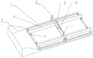
FIG. 1 is a schematic structural diagram of the present application;
fig. 2 is a schematic cross-sectional view of the present application.
In the figure: the automatic scraper comprises a main body 1, a scraper support 2, a scraper 3, a scraper, a guide rail 4, a collecting tank 5, a second strip-shaped hole 6, a sliding sleeve 7, a first strip-shaped hole 8, a guide pillar 9 and a fastening bolt 10.
Detailed Description
Referring to FIGS. 1-2: a road cavern repair device, the repair device comprising: the main body 1, the main body 1 is a square frame; two guide rails 4, which are arranged in parallel along the length direction of the main body 1 and are slidably assembled in the width direction of the main body 1; the scraper support 2 is bridged on the n-shaped support bodies on the two sides of the main body 1 and is assembled in a sliding mode in the length direction of the main body 1 through a sliding groove; the number of the scrapers 3 is two, one ends of the two scrapers 3 are mutually overlapped, the overlapped part is provided with a corresponding first strip-shaped hole 8, the middle part of the scraper bracket 2 is provided with a guide pillar 9, the guide pillar 9 penetrates through the first strip-shaped hole 8 to be slidably assembled with the scrapers 3, and the whole width is adjusted by adjusting the relative positions of the two scrapers 3; the lower edge of the scraper 3 passes through a gap between the two guide rails 4 and extends downwards, and the lower surface of the scraper 3 and the lower surface of the main body 1 are positioned on the same plane. Place main part 1 in waiting to mend the region, set up the width of two scraper blades 3 of adjustment to slide two guide rails 4 to its scraper blade 3 that corresponds, make scraper blade 3 slide in the space between two guide rails 4, pour cement into between two scraper blades 3, drive scraper blade 3 through scraper blade support 2 and slide, thereby trowel cement, simple structure, the operation of being convenient for.
In another optional embodiment of the present application, sliding grooves extending along the length direction of the main body 1 are formed on both sides of the main body 1, and tenons slidably fitted in the sliding grooves are arranged at the end portions of the scraper supports 2. Specifically, the sliding groove is a dovetail groove. The scraper blade bracket 2 is assembled in a sliding mode through a dovetail groove, sliding stability is guaranteed, and the scraper blade 3 keeps a certain height to move back and forth.
The one end that two scraper blades 3 kept away from each other all is equipped with sliding sleeve 7, in order to pass through sliding sleeve 7 slides along scraper blade support 2. One end of the scraper 3 is limited on the scraper bracket 2 through a sliding sleeve 7, and the other end is limited on the bracket through a guide post 9 and moves relatively in the width direction of the main body 1; thereby adjusting the width.
Specifically, the section of the scraper support 2 is square, and the sliding sleeve is a square sleeve which is correspondingly sleeved with the scraper support 2.
One end of the main body 1 is provided with a collecting groove 5, and the lower surface of the collecting groove 5 and the lower surface of the main body 1 are in the same plane. Set up collecting vat 5, scrape into collecting vat 5 with unnecessary cement, avoid extravagant, it is further, one side lower surface that main part 1 corresponds collecting vat 5 is equipped with the breach, and scraper blade 3 is strickleing off the in-process, will supply water cement to scrape into collecting vat 5 through the breach. The collecting gutter 5 is detachably connected to the main body 1 by bolts.
The lower edge of the scraper 3 is of a sawtooth structure so as to form an anti-skid groove on the surface of cement.
The guide post 9 is a screw post, and a butterfly nut is in threaded connection with the screw post so as to extrude the two scrapers 3 on the scraper bracket 2. The two scraping plates 3 are limited by tightening the butterfly nuts.
The both ends of guide rail 4 all are equipped with the fastening bolt 10 that corresponds main part 1, be equipped with the correspondence on the main part 1 fastening bolt 10, along the second bar hole 6 of traveller width direction extension, guide rail 4 will slide second bar hole 6 as required to set up the nut on fastening bolt 10, lock guide rail 4 after screwing.
Claims (10)
1. A road cavern repair device, characterized in that the repair device comprises:
the main body is a square frame;
the two guide rails are arranged in parallel along the length direction of the main body and are assembled in a sliding manner in the width direction of the main body;
the scraper supports are bridged on the n-shaped frame bodies on the two sides of the main body and are assembled in a sliding mode in the length direction of the main body through sliding grooves;
the scraper comprises two scrapers, one ends of the two scrapers are mutually overlapped, the overlapped part is provided with a corresponding first strip-shaped hole, the middle part of the scraper bracket is provided with a guide pillar, and the guide pillar penetrates through the first strip-shaped hole to be assembled with the scrapers in a sliding manner; the lower edge of the scraper passes through a gap between the two guide rails and extends downwards, and the lower surface of the scraper and the lower surface of the main body are located on the same plane.
2. The apparatus of claim 1, wherein the left and right sides of the main body are provided with sliding grooves extending along the length direction thereof, and the end of the scraper support is provided with a tenon slidably fitted in the sliding grooves.
3. The road pothole repair device of claim 2, wherein the sliding groove is a dovetail groove.
4. The apparatus for repairing a road pot hole according to claim 1, wherein the ends of the two scrapers which are far away from each other are provided with sliding sleeves, so as to slide along the scraper support through the sliding sleeves.
5. The apparatus for repairing a road pothole according to claim 4, wherein the cross section of the scraper support is square, and the sliding sleeve is a square sleeve correspondingly sleeved on the scraper support.
6. The apparatus for repairing a road pot hole according to claim 1, wherein a collecting groove is formed at one end of the main body, and a lower surface of the collecting groove is flush with a lower surface of the main body.
7. The apparatus for repairing a road pit according to claim 6, wherein a lower surface of the main body corresponding to one side of the collecting groove is provided with a notch.
8. The apparatus of claim 1, wherein the lower edge of the blade is of a saw-toothed configuration.
9. The road pothole repair device of claim 1, wherein the guide posts are wire posts that are threaded with butterfly nuts to squeeze two scrapers onto the scraper brackets.
10. The apparatus for repairing a road pot hole according to claim 1, wherein a sliding pillar corresponding to the main body is provided at each of both ends of the guide rail, and a second strip-shaped hole extending in a width direction of the sliding pillar corresponding to the sliding pillar is provided in the main body.
Priority Applications (1)
| Application Number | Priority Date | Filing Date | Title |
|---|---|---|---|
| CN202122361846.6U CN216074669U (en) | 2021-09-28 | 2021-09-28 | Road pit repairing equipment |
Applications Claiming Priority (1)
| Application Number | Priority Date | Filing Date | Title |
|---|---|---|---|
| CN202122361846.6U CN216074669U (en) | 2021-09-28 | 2021-09-28 | Road pit repairing equipment |
Publications (1)
| Publication Number | Publication Date |
|---|---|
| CN216074669U true CN216074669U (en) | 2022-03-18 |
Family
ID=80636373
Family Applications (1)
| Application Number | Title | Priority Date | Filing Date |
|---|---|---|---|
| CN202122361846.6U Active CN216074669U (en) | 2021-09-28 | 2021-09-28 | Road pit repairing equipment |
Country Status (1)
| Country | Link |
|---|---|
| CN (1) | CN216074669U (en) |
Cited By (1)
| Publication number | Priority date | Publication date | Assignee | Title |
|---|---|---|---|---|
| CN115233989A (en) * | 2022-06-20 | 2022-10-25 | 青岛环城建工集团有限公司 | Square template cement piece scraping equipment with limiting function for building construction |
-
2021
- 2021-09-28 CN CN202122361846.6U patent/CN216074669U/en active Active
Cited By (2)
| Publication number | Priority date | Publication date | Assignee | Title |
|---|---|---|---|---|
| CN115233989A (en) * | 2022-06-20 | 2022-10-25 | 青岛环城建工集团有限公司 | Square template cement piece scraping equipment with limiting function for building construction |
| CN115233989B (en) * | 2022-06-20 | 2024-04-05 | 青岛环城建工集团有限公司 | Square template cement piece equipment of striking off that has restriction function for construction |
Similar Documents
| Publication | Publication Date | Title |
|---|---|---|
| CN216074669U (en) | Road pit repairing equipment | |
| CN211489843U (en) | Steel construction cutting device for PC component | |
| CN108166354A (en) | A kind of mud-scraping apparatus of municipal construction road roller | |
| CN212223540U (en) | Bituminous paving device for municipal works | |
| CN116163192A (en) | Municipal road rapid repair structure and construction method thereof | |
| CN208201580U (en) | A kind of asphalt paving device | |
| CN202577915U (en) | Pasting machine | |
| CN205704655U (en) | For clearing up the frock of foamed concrete insulation blocks tray surface residue | |
| CN215441462U (en) | Road paving device for road and bridge | |
| CN220767606U (en) | Curb leveling layer leveling device | |
| CN112239989A (en) | Road surface crack patching device is used in traffic engineering construction | |
| CN220768218U (en) | A desilting device for water supply and drainage | |
| CN220685737U (en) | Concrete pavement repairing device | |
| CN219157361U (en) | Highway engineering maintenance is with portable watering device | |
| CN220150052U (en) | Pavement repairing device capable of rapidly repairing pavement cracks | |
| CN212742110U (en) | Cement spreading device for highway engineering | |
| CN219260642U (en) | Road leveling roller for road transformation | |
| CN220813357U (en) | Highway crack grouting repairing device | |
| CN216445733U (en) | Small road section flattening device after paving highway engineering asphalt | |
| CN218175492U (en) | Auxiliary spreading device of concrete paver | |
| CN216688953U (en) | Road maintenance is with pitch coating device | |
| CN216107990U (en) | Bituminous paving hole groove patching device | |
| CN211772955U (en) | Road and bridge crack reinforced structure | |
| CN109227911B (en) | Novel vacuum brick equipment | |
| CN219862336U (en) | Full-hydraulic movable trestle with good protection performance |
Legal Events
| Date | Code | Title | Description |
|---|---|---|---|
| GR01 | Patent grant | ||
| GR01 | Patent grant |