CN216066708U - Can purify panel grinding device of dust - Google Patents
Can purify panel grinding device of dust Download PDFInfo
- Publication number
- CN216066708U CN216066708U CN202122238008.XU CN202122238008U CN216066708U CN 216066708 U CN216066708 U CN 216066708U CN 202122238008 U CN202122238008 U CN 202122238008U CN 216066708 U CN216066708 U CN 216066708U
- Authority
- CN
- China
- Prior art keywords
- fixedly connected
- plate
- block
- polishing
- moving
- Prior art date
- Legal status (The legal status is an assumption and is not a legal conclusion. Google has not performed a legal analysis and makes no representation as to the accuracy of the status listed.)
- Active
Links
Images


Landscapes
- Grinding-Machine Dressing And Accessory Apparatuses (AREA)
Abstract
The utility model discloses a plate polishing device capable of purifying dust, which comprises two frame assemblies, two absorption assemblies and a polishing assembly, wherein the two absorption assemblies are fixedly arranged on the frame assemblies; the frame subassembly includes the bottom plate, the equal fixedly connected with riser in the left and right sides at bottom plate top, and roof fixed connection is passed through at the top of two risers, and the sliding surface of roof has the slider, the right side fixedly connected with fixed plate at roof top. According to the plate polishing device capable of purifying dust, the frame assembly, the absorption assembly and the polishing assembly are matched with each other, so that the plate polishing device can purify the dust generated in the polishing process synchronously, the body health of workers is guaranteed, the polishing disc is convenient to disassemble and replace, the whole disassembling and replacing process is time-saving and labor-saving, the work burden of the workers is greatly reduced, the practicability is high, and the plate polishing device is suitable for popularization and use.
Description
Technical Field
The utility model relates to the technical field of machinery, in particular to a plate polishing device capable of purifying dust.
Background
In the process of processing to panel, often need to use grinding device, current panel grinding device can not purify the dust that the in-process produced of polishing in step, and these dusts fly away can seriously influence staff's healthy in the air around to, current panel grinding device also is convenient not to tear open and change the mill, and the whole work of tearing open and changing wastes time and energy, has greatly increased staff's work burden.
SUMMERY OF THE UTILITY MODEL
The utility model aims to provide a plate polishing device capable of purifying dust so as to solve the problems in the background art.
In order to achieve the purpose, the utility model provides the following technical scheme: a plate polishing device capable of purifying dust comprises a frame assembly, two absorption assemblies and polishing assemblies, wherein the two absorption assemblies are fixedly arranged on the frame assembly, and the polishing assemblies are fixedly arranged on the frame assembly;
the frame component comprises a bottom plate, wherein vertical plates are fixedly connected to the left side and the right side of the top of the bottom plate, the tops of the two vertical plates are fixedly connected through a top plate, a sliding block is connected to the surface of the top plate in a sliding mode, a fixed plate is fixedly connected to the right side of the top plate, an electric push rod is fixedly installed on the right side of the fixed plate, the output end of the left side of the electric push rod penetrates through the fixed plate and extends to the outside of the fixed plate to be fixedly connected with the right side of the sliding block, a hydraulic cylinder is fixedly connected to the bottom of the sliding block, a movable plate is fixedly connected to the output end of the bottom of the hydraulic cylinder, a polishing motor is fixedly connected to the bottom of the movable plate, and a polishing rotating shaft is fixedly connected to an output shaft at the bottom of the polishing motor;
the absorption assembly comprises a water tank fixedly connected to the top of the movable plate, one side of the water tank, which is far away from the hydraulic cylinder, is fixedly connected with a fan, the bottom of the fan is fixedly connected with an air suction pipe, and the top of the fan is communicated with the water tank through an air outlet pipe;
the polishing component comprises a connecting block fixedly connected to the bottom of the polishing rotating shaft, the bottom of the connecting block is fixedly connected with an installation block, the bottom of the installation block is provided with a polishing disk, the left side and the right side of the top of the polishing disk are both fixedly connected with positioning rods, the top ends of the positioning rods penetrate through the installation block and extend to the outside of the installation block, a movable sleeve is sleeved on the surface of the connecting block, two sliding grooves are formed in the connecting block, movable blocks are connected onto the inner wall of the sliding grooves in a sliding mode, a movable rod is fixedly connected to one side, away from each other, of each movable block, a baffle is fixedly connected to one end, away from the movable blocks, of each movable block, an insertion block is fixedly connected to one side, close to the connecting block, of each insertion block, far away from the baffle, penetrates through the baffle and extends to the inside of each insertion block to be movably connected with the insertion block, and limiting plates are fixedly connected to the left side and the right side of the connecting block, the bottom fixedly connected with telescopic link of limiting plate, the bottom of telescopic link and the top fixed connection of shifting ring, the spring has been cup jointed on the surface of telescopic link, through spring fixed connection between limiting plate and the shifting ring, the equal fixedly connected with fixture block in the left and right sides of movable plate bottom, the bottom of fixture block runs through the baffle and extends to its inside rather than swing joint.
Preferably, the top of the polishing disc and the top of the mounting block are in contact with each other.
Preferably, the movable rod is movably connected with the connecting block.
Preferably, the bottom end of the spring is fixedly connected with the top of the moving ring, and the top end of the spring is fixedly connected with the bottom of the limiting plate.
Compared with the prior art, the utility model has the following beneficial effects:
according to the plate polishing device capable of purifying dust, the frame assembly, the absorption assembly and the polishing assembly are matched with each other, so that the plate polishing device can purify the dust generated in the polishing process synchronously, the body health of workers is guaranteed, the polishing disc is convenient to disassemble and replace, the whole disassembling and replacing process is time-saving and labor-saving, the work burden of the workers is greatly reduced, the practicability is high, and the plate polishing device is suitable for popularization and use.
Drawings
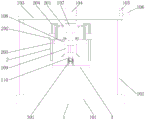
FIG. 1 is a structural cross-sectional view in elevation of the present invention;
FIG. 2 is a structural cross-sectional view in elevation of the grinding assembly of the present invention;
FIG. 3 is a schematic top view of the connecting block and the moving ring of the present invention.
In the figure: the polishing machine comprises a frame component 1, a bottom plate 101, a vertical plate 102, a top plate 103, a sliding block 104, a fixed plate 105, an electric push rod 106, a hydraulic cylinder 107, a moving plate 108, a polishing motor 109, a polishing rotating shaft 110, an absorption component 2, a water tank 201, a fan 202, an air suction pipe 203, an air outlet pipe 204, a polishing component 3, a connecting block 301, an installation block 302, a polishing disc 303, a positioning rod 304, a moving ring 305, a sliding chute 306, a moving block 307, a moving rod 308, a baffle 309, an insertion block 310, a limiting plate 311, a telescopic rod 312, a spring 313 and a clamping block 314.
Detailed Description
The technical solutions in the embodiments of the present invention will be clearly and completely described below with reference to the drawings in the embodiments of the present invention, and it is obvious that the described embodiments are only a part of the embodiments of the present invention, and not all of the embodiments. All other embodiments, which can be derived by a person skilled in the art from the embodiments given herein without making any creative effort, shall fall within the protection scope of the present invention.
Referring to fig. 1-3, a plate polishing device capable of purifying dust includes a frame assembly 1, two absorption assemblies 2 and a polishing assembly 3, wherein the two absorption assemblies 2 are both fixedly mounted on the frame assembly 1, and the polishing assembly 3 is fixedly mounted on the frame assembly 1.
Frame assembly 1 includes bottom plate 101, the equal fixedly connected with riser 102 in the left and right sides at bottom plate 101 top, roof 103 fixed connection is passed through at the top of two risers 102, the sliding surface connection of roof 103 has slider 104, the right side fixedly connected with fixed plate 105 at roof 103 top, the right side fixed mounting of fixed plate 105 has electric putter 106, the left output of electric putter 106 runs through fixed plate 105 and extends to its outside and slider 104's right side fixed connection, slider 104's bottom fixedly connected with pneumatic cylinder 107, fixedly connected with movable plate 108 on the output of pneumatic cylinder 107 bottom, the bottom fixedly connected with grinding motor 109 of movable plate 108, fixedly connected with grinding shaft 110 on the output shaft of grinding motor 109 bottom.
The absorption assembly 2 comprises a water tank 201 fixedly connected to the top of the moving plate 108, a water filling port is formed in the top of the water tank 201, the bottom of one side of the water tank 201 is connected with a water outlet pipe, a valve is installed on the water outlet pipe, one side of the water tank 201, away from the hydraulic cylinder 107, is fixedly connected with a fan 202, the bottom of the fan 202 is fixedly connected with an air suction pipe 203, and the top of the fan 202 is communicated with the water tank 201 through an air outlet pipe 204.
The polishing assembly 3 comprises a connecting block 301 fixedly connected to the bottom of the polishing rotating shaft 110, an installation block 302 is fixedly connected to the bottom of the connecting block 301, a polishing disc 303 is arranged at the bottom of the installation block 302, the top of the polishing disc 303 is in contact with the top of the installation block 302, positioning rods 304 are fixedly connected to the left side and the right side of the top of the polishing disc 303, the top ends of the positioning rods 304 penetrate through the installation block 302 and extend to the outside of the installation block 302, a moving ring 305 is movably sleeved on the surface of the connecting block 301, two sliding grooves 306 are formed in the connecting block 301, moving blocks 307 are slidably connected to the inner wall of the sliding grooves 306, moving rods 308 are fixedly connected to the sides of the two moving blocks 307 far away from each other, a baffle 309 is fixedly connected to one end of the moving rod 308 far away from the moving blocks 307, the moving rod 308 is movably connected with the connecting block 301, an insert 310 is fixedly connected to one side of the baffle 309 near the connecting block 301, one side of the insert 310 far away from the baffle 309 penetrates through the baffle and extends to the inside of the insert 309 and is movably connected with the insert 309, the left side and the right side of the connecting block 301 are fixedly connected with a limiting plate 311, the bottom of the limiting plate 311 is fixedly connected with an expansion rod 312, the bottom end of the expansion rod 312 is fixedly connected with the top of the moving ring 305, the surface of the expansion rod 312 is sleeved with a spring 313, the limiting plate 311 is fixedly connected with the moving ring 305 through the spring 313, the bottom end of the spring 313 is fixedly connected with the top of the moving ring 305, the top end of the spring 313 is fixedly connected with the bottom of the limiting plate 311, the left side and the right side of the bottom of the moving plate 108 are fixedly connected with a clamping block 314, the bottom of the clamping block 314 penetrates through the baffle 309 and extends to the interior of the baffle 309 to be movably connected with the baffle, through the mutual matching of the frame component 1, the absorption component 2 and the polishing component 3, the plate polishing device capable of purifying dust is realized, the plate polishing device can synchronously purify the dust generated in the polishing process, and the health of workers is ensured, and still make the mill 303 conveniently tear open and trade, whole tear open and trade process labour saving and time saving has greatly alleviateed staff's work burden, and the practicality is high, is fit for using widely.
During the use, the process of polishing is the open technology, this is not enough repeated here, in the in-process of polishing, fan 202 absorbs the air that carries the dust through breathing pipe 203, and carry out dust disposal with the aquatic of air admission water tank 201 through outlet duct 204, when needing to tear open and trade the polishing dish 303, the staff upwards stimulates shift ring 305, shift ring 305 drives fixture block 314 and breaks away from baffle 309, later operate baffle 309 one by one, to the direction pulling baffle 309 of keeping away from connecting block 301, baffle 309 drives inserted block 310 and breaks away from locating lever 304, can let another one person take polishing dish 303 and operate another baffle 309 again this moment, when two inserted blocks 310 break away from two locating levers 304 respectively, polishing dish 303 can be because gravity whereabouts, polishing dish 303 drives locating lever 304 and breaks away from installation piece 302.
In summary, the following steps: this but panel grinding device of dust purification through mutually supporting of frame subassembly 1, absorption subassembly 2 and grinding component 3, has solved the problem of proposing among the background art.
Although embodiments of the present invention have been shown and described, it will be appreciated by those skilled in the art that changes, modifications, substitutions and alterations can be made in these embodiments without departing from the principles and spirit of the utility model, the scope of which is defined in the appended claims and their equivalents.
Claims (4)
1. The utility model provides a but panel grinding device of dust purification, includes frame subassembly (1), absorption subassembly (2) and grinding component (3), its characterized in that: the number of the absorption assemblies (2) is two, the absorption assemblies are fixedly arranged on the frame assembly (1), and the grinding assembly (3) is fixedly arranged on the frame assembly (1);
the frame component (1) comprises a bottom plate (101), the left side and the right side of the top of the bottom plate (101) are fixedly connected with vertical plates (102), the tops of the two vertical plates (102) are fixedly connected through a top plate (103), the surface of the top plate (103) is connected with a sliding block (104) in a sliding way, the right side of the top plate (103) is fixedly connected with a fixed plate (105), an electric push rod (106) is fixedly arranged on the right side of the fixed plate (105), the output end of the left side of the electric push rod (106) penetrates through the fixed plate (105) and extends to the outside of the fixed plate to be fixedly connected with the right side of the sliding block (104), the bottom of the slide block (104) is fixedly connected with a hydraulic cylinder (107), the output end of the bottom of the hydraulic cylinder (107) is fixedly connected with a moving plate (108), the bottom of the moving plate (108) is fixedly connected with a polishing motor (109), and an output shaft at the bottom of the polishing motor (109) is fixedly connected with a polishing rotating shaft (110);
the absorption assembly (2) comprises a water tank (201) fixedly connected to the top of the moving plate (108), one side, away from the hydraulic cylinder (107), of the water tank (201) is fixedly connected with a fan (202), the bottom of the fan (202) is fixedly connected with an air suction pipe (203), and the top of the fan (202) is communicated with the water tank (201) through an air outlet pipe (204);
the polishing assembly (3) comprises a connecting block (301) fixedly connected to the bottom of a polishing rotating shaft (110), the bottom of the connecting block (301) is fixedly connected with an installation block (302), the bottom of the installation block (302) is provided with a polishing disc (303), the left side and the right side of the top of the polishing disc (303) are fixedly connected with positioning rods (304), the top end of each positioning rod (304) penetrates through the installation block (302) and extends to the outside of the installation block, a moving ring (305) is movably sleeved on the surface of the connecting block (301), two sliding grooves (306) are formed in the connecting block (301), a moving block (307) is slidably connected to the inner wall of each sliding groove (306), a moving rod (308) is fixedly connected to one side, away from each other, of the two moving blocks (307), and a baffle plate (309) is fixedly connected to one end, away from the moving rod (308), of the moving block (307), baffle (309) are close to one side fixedly connected with inserted block (310) of connecting block (301), one side that baffle (309) was kept away from in inserted block (310) runs through baffle (309) and extends to its inside rather than swing joint, the equal fixedly connected with limiting plate (311) in both sides about connecting block (301), the bottom fixedly connected with telescopic link (312) of limiting plate (311), the bottom of telescopic link (312) and the top fixed connection of shift ring (305), spring (313) have been cup jointed on the surface of telescopic link (312), through spring (313) fixed connection between limiting plate (311) and shift ring (305), the equal fixedly connected with fixture block (314) in both sides about shift plate (108) bottom, the bottom of fixture block (314) runs through baffle (309) and extends to its inside rather than swing joint.
2. The plate grinding device capable of purifying dust as claimed in claim 1, wherein: the top of the polishing disc (303) is contacted with the top of the mounting block (302).
3. The plate grinding device capable of purifying dust as claimed in claim 1, wherein: the movable rod (308) is movably connected with the connecting block (301).
4. The plate grinding device capable of purifying dust as claimed in claim 1, wherein: the bottom end of the spring (313) is fixedly connected with the top of the moving ring (305), and the top end of the spring (313) is fixedly connected with the bottom of the limiting plate (311).
Priority Applications (1)
| Application Number | Priority Date | Filing Date | Title |
|---|---|---|---|
| CN202122238008.XU CN216066708U (en) | 2021-09-15 | 2021-09-15 | Can purify panel grinding device of dust |
Applications Claiming Priority (1)
| Application Number | Priority Date | Filing Date | Title |
|---|---|---|---|
| CN202122238008.XU CN216066708U (en) | 2021-09-15 | 2021-09-15 | Can purify panel grinding device of dust |
Publications (1)
| Publication Number | Publication Date |
|---|---|
| CN216066708U true CN216066708U (en) | 2022-03-18 |
Family
ID=80676589
Family Applications (1)
| Application Number | Title | Priority Date | Filing Date |
|---|---|---|---|
| CN202122238008.XU Active CN216066708U (en) | 2021-09-15 | 2021-09-15 | Can purify panel grinding device of dust |
Country Status (1)
| Country | Link |
|---|---|
| CN (1) | CN216066708U (en) |
-
2021
- 2021-09-15 CN CN202122238008.XU patent/CN216066708U/en active Active
Similar Documents
| Publication | Publication Date | Title |
|---|---|---|
| CN213613662U (en) | Stamping die with deburring function | |
| CN108500847A (en) | Auto parts machinery polishing tool | |
| CN216066708U (en) | Can purify panel grinding device of dust | |
| CN209970368U (en) | High-efficient grinding device is used in production of smoke damper | |
| CN219504403U (en) | Automobile transmission shaft part polishing device | |
| CN216398947U (en) | Automobile parts production line assembly platform protection casing | |
| CN216371576U (en) | Environment-friendly railway track accessory grinding device with dust removal function | |
| CN214869467U (en) | Grinding device is used in processing of dull and stereotyped shell mould of plastic | |
| CN215588804U (en) | Surface pretreatment equipment for machining ferrule | |
| CN116079798A (en) | Petrochemical machinery cutting device | |
| CN113547342B (en) | Rotary multi-station man-machine cooperation part machining table | |
| CN206047889U (en) | A kind of milling tools case | |
| CN208451264U (en) | A kind of filter case process equipment | |
| CN111113222B (en) | Adjustable intelligent carbon sliding plate inner and outer arc dust-free processing equipment and polishing method thereof | |
| CN210411856U (en) | Protection device for stamping die | |
| CN209504601U (en) | A kind of dust suction switching device of dust arrester | |
| CN113103084A (en) | A hydro-cylinder inner wall grinding device for vehicle | |
| CN114160715B (en) | Equidistant steel bar cutting device for constructional engineering | |
| CN208409476U (en) | Grinding machine is used in a kind of machining of environment-friendly type | |
| CN218136432U (en) | Clamping and fixing device for mold production | |
| CN213673261U (en) | Edge grinding device for processing car lamp shade | |
| CN216644523U (en) | Stamping forming's malleation supply-air outlet panel | |
| CN215847380U (en) | Power plant's dry sediment machine sprocket processing is with edging device | |
| CN220372489U (en) | Metal round tube end face welding equipment | |
| CN219702938U (en) | Top movable suction purifying device |
Legal Events
| Date | Code | Title | Description |
|---|---|---|---|
| GR01 | Patent grant | ||
| GR01 | Patent grant |