CN216048768U - High-efficient heating device of heat pump stoving components of a whole that can function independently closed loop - Google Patents
High-efficient heating device of heat pump stoving components of a whole that can function independently closed loop Download PDFInfo
- Publication number
- CN216048768U CN216048768U CN202121253942.2U CN202121253942U CN216048768U CN 216048768 U CN216048768 U CN 216048768U CN 202121253942 U CN202121253942 U CN 202121253942U CN 216048768 U CN216048768 U CN 216048768U
- Authority
- CN
- China
- Prior art keywords
- drying chamber
- drying
- induced draft
- draft fan
- air
- Prior art date
- Legal status (The legal status is an assumption and is not a legal conclusion. Google has not performed a legal analysis and makes no representation as to the accuracy of the status listed.)
- Active
Links
Images


Landscapes
- Drying Of Solid Materials (AREA)
Abstract
The utility model discloses a heat pump drying split closed-loop efficient heating device which comprises a drying chamber, a heating box and a heat circulation structure, wherein the drying chamber is provided with a heating box; the drying chamber is connected with the heating box through a thermal cycle structure; the arrangement of the flow dispersion plate and the gas collecting hood is more favorable for improving the penetrability of airflow, so that the air in the drying chamber is uniformly distributed, the materials can be uniformly and fully baked, and the drying quality is improved; the arrangement of the first induced draft fan and the second induced draft fan enables the internal air of the whole device to form heat circulation, so that energy is saved; the arrangement of the dehumidifier reduces the water vapor in the dried circulating air, and ensures the drying quality; the rotation of a net drum increases the contact area between the materials to be dried and hot air inside the net drum, so that the drying and dehumidifying are more uniform, and the drying effect is improved.
Description
Technical Field
The utility model relates to a heating device, in particular to a heat pump drying split closed-loop efficient heating device.
Background
Some agricultural and sideline products, medicinal materials, tobacco, wood and the like in the prior art need drying treatment, and various drying devices are aimed at, and a heat pump dryer is one of the drying devices. The heat pump dryer is a heat lifting device, a high-temperature heat pump dryer group absorbs heat from the surrounding environment by utilizing the inverse Carnot principle and transfers the heat to a heated object, the working principle of the high-temperature heat pump dryer group is the same as that of a refrigerator, the high-temperature heat pump dryer group works according to the inverse Carnot cycle, and the working temperature range is different; the common heat pump dryer has single functionality, does not have a corresponding auxiliary dehumidifying tool, and does not have a good rotating device to enable the drying and dehumidifying effects to be more uniform.
Disclosure of Invention
The utility model aims to provide a split closed-loop efficient heating device for drying a heat pump, so as to solve the problems in the background technology.
In order to achieve the purpose, the utility model provides the following technical scheme:
a heat pump drying split closed-loop efficient heating device comprises a drying chamber, a heating box and a heat circulation structure; the drying chamber and the heating box are connected through a thermal cycle structure.
As a further scheme of the utility model: the front surface of the drying chamber is hinged with a feeding door; the inner side wall of the lower part of the drying chamber is fixedly connected with a flow dispersing plate, and a plurality of through holes are uniformly formed in the flow dispersing plate.
As a further scheme of the utility model: the middle part of the drying chamber and the top surface of the flow dispersing plate are provided with rolling drying devices, and each rolling drying device comprises a net drum, a roller bracket, a rotating shaft, a motor, a feeding hole and a discharging hole; the motor is fixedly connected to the inner side wall of the drying chamber, the output end of the motor is fixedly connected with one end of a rotating shaft fixedly connected with two ends of the net barrel, and the other end of the rotating shaft is rotatably connected to the inner side wall of the drying chamber through a bearing; a feed inlet is hinged on the side wall of the cylinder body of the net cylinder, a discharge outlet is arranged on the cylinder body of the net cylinder, and a sealing plug is hinged on the discharge outlet; the group of roller supports are symmetrically arranged at the bottom of the net drum, the bottom surfaces of the roller supports are fixedly connected to the flow dispersing plate, the top surfaces of the roller supports are arc-shaped and matched with the net drum in shape, and the top surfaces of the roller supports are in contact connection with the net drum.
As a further scheme of the utility model: the thermal cycle structure comprises a first induced draft fan, a gas collecting hood, a gas collecting main pipe, a second induced draft fan and a dehumidifier; a first induced draft fan is fixedly connected with the air inlet hole formed in the left side wall of the bottom of the drying chamber and below the flow dispersing plate; a plurality of air outlet holes uniformly formed in the top of the drying chamber are respectively and fixedly connected with a gas collecting hood; the gas collecting hood is respectively connected with a gas collecting main pipe through an air pipeline; the air pipelines are provided with air valves; the top surface of the gas collection header pipe is fixedly connected with a second draught fan, the input end of the second draught fan is connected with the air outlet of the gas collection header pipe through a pipeline, the output end of the second draught fan is connected with the input end of a dehumidifier through a pipeline, the dehumidifier is fixedly connected to the top surface of the heating box, and the output end of the dehumidifier is connected with the air inlet hole of the heating box through a pipeline.
As a still further scheme of the utility model: the heating box comprises a third induced draft fan, an evaporator, a condenser and a compressor; an air inlet is formed in the left side wall of the heating box, a third induced draft fan is fixedly connected to the air inlet, and a filter screen is arranged on the outer side of the third induced draft fan; an evaporator is fixedly installed on one side, close to the third induced draft fan, inside the heating box, a condenser is fixedly installed on one side, far away from the third induced draft fan, inside the drying chamber, and a compressor is fixedly installed on the inner wall of the top of the drying chamber; the output end of the evaporator is connected with the input end of the compressor, the input end of the evaporator is connected with the output end of the condenser, and the output end of the compressor is connected with the input end of the condenser; an air outlet hole arranged on the right side wall of the heating box is connected with an air inlet hole of the drying chamber through a pipeline.
Compared with the prior art, the utility model has the beneficial effects that:
the arrangement of the flow dispersion plate and the gas collecting hood is more favorable for improving the penetrability of airflow, so that the air in the drying chamber is uniformly distributed, the materials can be uniformly and fully baked, and the drying quality is improved; the arrangement of the first induced draft fan and the second induced draft fan enables the internal air of the whole device to form heat circulation, so that energy is saved; the arrangement of the dehumidifier reduces the water vapor in the dried circulating air, and ensures the drying quality; the rotation of a net drum increases the contact area between the materials to be dried and hot air inside the net drum, so that the drying and dehumidifying are more uniform, and the drying effect is better.
Drawings
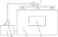
Fig. 1 is a schematic structural diagram of a heat pump drying split closed-loop efficient heating device.
Fig. 2 is an appearance structure schematic diagram of a heat pump drying split closed-loop high-efficiency heating device.
Fig. 3 is a schematic side structure view of a mesh drum in the heat pump drying split closed-loop high-efficiency heating device.
In the figure: 1. a drying chamber; 2. a heating box; 3. a thermal cycling structure; 11. a feed gate; 12. a flow dispersing plate; 13. a net drum; 14. a drum support; 15. a rotating shaft; 16. a motor; 17. a feed inlet; 18. a discharge port; 21. a third induced draft fan; 22. an evaporator; 23. a condenser; 24. a compressor; 25. filtering with a screen; 31. a first induced draft fan; 32. a gas-collecting hood; 33. a gas collection header pipe; 34. a second induced draft fan; 35. a dehumidifier; 36. an air valve.
Detailed Description
The technical solutions in the embodiments of the present invention will be clearly and completely described below with reference to the drawings in the embodiments of the present invention, and it is obvious that the described embodiments are only a part of the embodiments of the present invention, and not all of the embodiments. All other embodiments, which can be derived by a person skilled in the art from the embodiments given herein without making any creative effort, shall fall within the protection scope of the present invention.
Referring to fig. 1 to 3, in an embodiment of the present invention, a heat pump drying split closed-loop high-efficiency heating apparatus includes a drying chamber 1, a heating box 2, and a heat circulation structure 3; the drying chamber 1 and the heating box 2 are connected by a thermal cycle structure 3.
The front surface of the drying chamber 1 is hinged with a feeding door 11; the inner side wall of the lower part of the drying chamber 1 is fixedly connected with a flow dispersing plate 12, a plurality of through holes are uniformly formed in the flow dispersing plate 12, and the hot air entering the drying chamber 1 is uniformly dispersed by the uniformly formed through holes, so that the materials can be uniformly and fully baked.
A rolling drying device is arranged in the middle of the drying chamber 1 and on the top surface of the flow dispersing plate 12, and comprises a net drum 13, a roller bracket 14, a rotating shaft 15, a motor 16, a feeding hole 17 and a discharging hole 18; the motor 16 is fixedly connected to the inner side wall of the drying chamber 1, the output end of the motor 16 is fixedly connected with one end of a rotating shaft 15 fixedly connected with two ends of the net cylinder 13, and the other end of the rotating shaft 15 is rotatably connected to the inner side wall of the drying chamber 1 through a bearing; a feed inlet 17 is hinged on the side wall of the cylinder body of the net cylinder 13, a discharge outlet 18 is arranged on the cylinder body of the net cylinder 13, and a sealing plug is hinged on the discharge outlet 18; the group of roller supports 14 are symmetrically arranged at the bottom of the net drum 13, the bottom surfaces of the roller supports 14 are fixedly connected to the flow dispersing plate 12, the top surface of each roller support 14 is arc-shaped and matched with the net drum 13 in shape, and the top surface of each roller support 14 is in contact connection with the net drum 13.
The thermal cycle structure 3 comprises a first induced draft fan 31, a gas collecting hood 32, a gas collecting main pipe 33, a second induced draft fan 34 and a dehumidifier 35; a first induced draft fan 31 is fixedly connected with the air inlet arranged on the left side wall of the bottom of the drying chamber 1 and below the flow dispersing plate 12; a plurality of air outlet holes uniformly formed in the top of the drying chamber 1 are respectively and fixedly connected with a gas collecting hood 32; the gas collecting hoods 32 are respectively connected with a gas collecting main pipe 33 through air pipelines; the air pipelines are provided with air valves 36; the top surface of the gas collecting main pipe 33 is fixedly connected with a second induced draft fan 34, the input end of the second induced draft fan 34 is connected with the air outlet of the gas collecting main pipe 33 through a pipeline, the output end of the second induced draft fan 34 is connected with the input end of a dehumidifier 35 through a pipeline, the dehumidifier 35 is fixedly connected with the top surface of the heating box 2, and the output end of the dehumidifier 35 is connected with the air inlet hole of the heating box 2 through a pipeline.
The arrangement of the flow dispersing plate 12 and the air collecting cover 32 is more favorable for improving the penetrability of air flow, so that the air in the drying chamber 1 is uniformly distributed, the materials can be uniformly and fully baked, and the drying quality is improved; the arrangement of the first induced draft fan 31 and the second induced draft fan 34 enables the internal air of the whole device to form heat circulation, and energy is saved.
The heating box 2 comprises a third induced draft fan 21, an evaporator 22, a condenser 23 and a compressor 24; an air inlet hole is formed in the left side wall of the heating box 2, a third induced draft fan 21 is fixedly connected to the air inlet hole, and a filter screen 25 is arranged on the outer side of the third induced draft fan 21 and used for blocking dust particles in the air; an evaporator 22 is fixedly installed on one side, close to the third induced draft fan 21, inside the heating box 2, a condenser 23 is fixedly installed on one side, far away from the third induced draft fan 21, inside the drying chamber 1, and a compressor 24 is fixedly installed on the inner wall of the top of the drying chamber 1; the output end of the evaporator 22 is connected with the input end of the compressor 24, the input end of the evaporator 22 is connected with the output end of the condenser 23, and the output end of the compressor 24 is connected with the input end of the condenser 23; an air outlet hole arranged on the right side wall of the heating box 2 is connected with an air inlet hole of the drying chamber 1 through a pipeline.
The working principle of the utility model is as follows:
opening the feeding door 11, and adding the materials to be dried into the net barrel 13 from the feeding hole 17; the compressor 24 delivers the refrigerant agent with high temperature and high pressure to the condenser 23, then to the evaporator 22, and finally to the compressor 24, and the cycle is repeated; the first induced draft fan 31 and the second induced draft fan 21 convey outside air to the interior of the heating box 2, and the air is heated by the condenser 23 and then enters the drying chamber 1 through a pipeline; hot air uniformly enters the rolling drying device through the through holes of the flow dispersing plate 12 to dry the materials to be dried in the net cylinder 13; the output end of the motor 16 drives the rotating shaft 15 to synchronously rotate, the rotating shaft 15 drives the net barrel 13 to synchronously rotate, and the rotation of the net barrel 13 increases the contact area of the materials to be dried in the net barrel and hot air, so that the drying and the dehumidification are more uniform, and the drying effect is better; the vapor produced by drying and the air enter the heating box 2 after being dehumidified by the thermal cycle structure 3 for continuous drying, so that the waste of heat is avoided.
In the description of the present invention, it should be noted that unless otherwise explicitly stated or limited, the terms "mounted," "connected," and "connected" are to be construed broadly, e.g., as meaning either a fixed connection, a removable connection, or an integral connection, a mechanical connection, or an electrical connection; they may be connected directly or indirectly through intervening media, or they may be interconnected between two elements. The specific meaning of the above terms in the present invention can be understood by those of ordinary skill in the art through specific situations.
Although the present invention has been described in detail with reference to the foregoing embodiments, it will be apparent to those skilled in the art that various changes in the embodiments and/or modifications of the utility model can be made, and equivalents and modifications of some features of the utility model can be made without departing from the spirit and scope of the utility model.
Claims (3)
1. A heat pump drying split closed-loop efficient heating device comprises a drying chamber (1), a heating box (2) and a heat circulation structure (3); the drying device is characterized in that the drying chamber (1) is connected with the heating box (2) through a heat circulation structure (3); the front surface of the drying chamber (1) is hinged with a feeding door (11); a flow dispersing plate (12) is fixedly connected to the inner side wall of the lower part of the drying chamber (1), and a plurality of through holes are uniformly formed in the flow dispersing plate (12); a rolling drying device is arranged in the middle of the drying chamber (1) and on the top surface of the flow dispersing plate (12), and comprises a net drum (13), a roller bracket (14), a rotating shaft (15), a motor (16), a feeding hole (17) and a discharging hole (18); the motor (16) is fixedly connected to the inner side wall of the drying chamber (1), the output end of the motor (16) is fixedly connected with one end of a rotating shaft (15) fixedly connected with two ends of the net barrel (13), and the other end of the rotating shaft (15) is rotatably connected to the inner side wall of the drying chamber (1) through a bearing; a feed inlet (17) is hinged on the side wall of the cylinder body of the net cylinder (13), a discharge outlet (18) is arranged on the cylinder body of the net cylinder (13), and a sealing plug is hinged on the discharge outlet (18); the group of roller supports (14) are symmetrically arranged at the bottom of the net drum (13), the bottom surfaces of the roller supports (14) are fixedly connected to the flow dispersing plate (12), the top surfaces of the roller supports (14) are arc-shaped and matched with the net drum (13), and the top surfaces of the roller supports (14) are in contact connection with the net drum (13).
2. The heat pump drying split closed-loop efficient heating device according to claim 1, wherein the heat cycle structure (3) comprises a first induced draft fan (31), a gas collecting hood (32), a gas collecting main (33), a second induced draft fan (34) and a dehumidifier (35); a first induced draft fan (31) is fixedly connected with the air inlet arranged on the left side wall of the bottom of the drying chamber (1) and below the flow dispersing plate (12); a plurality of air outlet holes uniformly formed in the top of the drying chamber (1) are respectively and fixedly connected with a gas collecting hood (32); the gas collecting hood (32) is respectively connected with a gas collecting main pipe (33) through an air pipeline; the air pipelines are provided with air valves (36); gas collecting house steward (33) top surface fixed connection second draught fan (34), the input of second draught fan (34) passes through the pipeline and is connected with the air outlet of gas collecting house steward (33), the output of second draught fan (34) passes through the pipeline and is connected with the input of dehumidifier (35), dehumidifier (35) fixed connection is at the top surface of heating cabinet (2), the output of dehumidifier (35) passes through the air inlet connection of pipeline and heating cabinet (2).
3. The heat pump drying split closed-loop efficient heating device according to claim 1, wherein the heating box (2) comprises a third induced draft fan (21), an evaporator (22), a condenser (23) and a compressor (24); an air inlet hole is formed in the left side wall of the heating box (2), a third induced draft fan (21) is fixedly connected to the air inlet hole, and a filter screen (25) is arranged on the outer side of the third induced draft fan (21); an evaporator (22) is fixedly installed on one side, close to the third induced draft fan (21), in the heating box (2), a condenser (23) is fixedly installed on one side, far away from the third induced draft fan (21), in the drying chamber (1), and a compressor (24) is fixedly installed on the inner wall of the top of the drying chamber (1); the output end of the evaporator (22) is connected with the input end of the compressor (24), the input end of the evaporator (22) is connected with the output end of the condenser (23), and the output end of the compressor (24) is connected with the input end of the condenser (23); an air outlet hole arranged on the right side wall of the heating box (2) is connected with an air inlet hole of the drying chamber (1) through a pipeline.
Priority Applications (1)
| Application Number | Priority Date | Filing Date | Title |
|---|---|---|---|
| CN202121253942.2U CN216048768U (en) | 2021-06-07 | 2021-06-07 | High-efficient heating device of heat pump stoving components of a whole that can function independently closed loop |
Applications Claiming Priority (1)
| Application Number | Priority Date | Filing Date | Title |
|---|---|---|---|
| CN202121253942.2U CN216048768U (en) | 2021-06-07 | 2021-06-07 | High-efficient heating device of heat pump stoving components of a whole that can function independently closed loop |
Publications (1)
| Publication Number | Publication Date |
|---|---|
| CN216048768U true CN216048768U (en) | 2022-03-15 |
Family
ID=80614675
Family Applications (1)
| Application Number | Title | Priority Date | Filing Date |
|---|---|---|---|
| CN202121253942.2U Active CN216048768U (en) | 2021-06-07 | 2021-06-07 | High-efficient heating device of heat pump stoving components of a whole that can function independently closed loop |
Country Status (1)
| Country | Link |
|---|---|
| CN (1) | CN216048768U (en) |
-
2021
- 2021-06-07 CN CN202121253942.2U patent/CN216048768U/en active Active
Similar Documents
| Publication | Publication Date | Title |
|---|---|---|
| CN1973077B (en) | Dryer | |
| CN207610489U (en) | A kind of tea drier | |
| CN202380300U (en) | Dryer provided with condensate recycling device | |
| CN112273699A (en) | Sheet cut tobacco drying equipment with flow passing section | |
| CN208536530U (en) | A kind of energy-saving and environment-friendly hot air circulation air energy heat pump dryer | |
| CN204154088U (en) | A kind of totally-enclosed heat pump drying dehumidifying integrated machine | |
| CN216048768U (en) | High-efficient heating device of heat pump stoving components of a whole that can function independently closed loop | |
| CN111023727A (en) | Solar dryer | |
| CN218600198U (en) | Bamboo shoot drying equipment | |
| CN216770066U (en) | Energy-saving and emission-reducing drying device for processing bird's nest | |
| CN207991162U (en) | A kind of drying unit for Chinese medicine production | |
| CN207649280U (en) | A kind of chemical fertilizer production dryer | |
| CN217465307U (en) | Heat pump drying equipment | |
| CN206504551U (en) | A kind of drying unit | |
| CN211932517U (en) | Closed circulation tobacco leaf bakery of area condensation dehumidification function | |
| CN211476527U (en) | Solar dryer | |
| CN212139278U (en) | Split type closed circulation heat pump tobacco flue-curing barn | |
| CN210275663U (en) | Tunnel type food toasts case and uses firing equipment | |
| CN2644467Y (en) | Air-dry mechanism of normal temperature clothes dryer | |
| CN202380302U (en) | Dryer adopting air throttle to control air volume | |
| CN207284026U (en) | The Electric Appliance Cabinet of internal circulation drier is installed | |
| CN103438682B (en) | Heat pump drying equipment | |
| CN211290793U (en) | High-efficient air energy heat pump drying chamber of fruit vegetables | |
| CN206852011U (en) | A kind of board-like energy-conservation hydrofuge machine of barn | |
| CN205399077U (en) | Energy -efficient closed stoving room |
Legal Events
| Date | Code | Title | Description |
|---|---|---|---|
| GR01 | Patent grant | ||
| GR01 | Patent grant |