CN216011117U - Bilateral air-blowing humidifier - Google Patents
Bilateral air-blowing humidifier Download PDFInfo
- Publication number
- CN216011117U CN216011117U CN202121924681.2U CN202121924681U CN216011117U CN 216011117 U CN216011117 U CN 216011117U CN 202121924681 U CN202121924681 U CN 202121924681U CN 216011117 U CN216011117 U CN 216011117U
- Authority
- CN
- China
- Prior art keywords
- water
- atomizing
- double
- humidifier
- mist
- Prior art date
- Legal status (The legal status is an assumption and is not a legal conclusion. Google has not performed a legal analysis and makes no representation as to the accuracy of the status listed.)
- Active
Links
Images


Abstract
The utility model discloses a bilateral blowing humidifier which comprises a shell, wherein a water storage cavity, an atomization cavity and a mist outlet channel are arranged in the shell, and the upper end of the mist outlet channel is provided with a mist outlet; the double-side blow humidifier further includes: the atomizing devices are arranged in the atomizing cavity, the number of the atomizing devices is at least 2, and the atomizing devices are arranged on the periphery of the mist outlet channel at intervals; the mist guiding device is arranged in the shell and corresponds to each atomizing device; according to the humidifier, at least two groups of atomization devices for atomizing water in the atomization cavity are arranged in the atomization cavity of the shell, so that the atomization amount of the humidifier is increased, the fog guide devices which correspond to the atomization devices one by one are arranged in the shell, the fog outlet efficiency of the humidifier is improved, the requirement of the humidifier for uniform fog outlet of various humidifiers with different fog outlet effects is met, the working time of the humidifier for enabling the surrounding environment to reach proper relative humidity is shortened, and the user experience is improved.
Description
Technical Field
The utility model relates to a bilateral blowing humidifier.
Background
In the prior art, due to the limitation of the humidifier, the air outlet effect of the humidifier is not ideal, the humidification quantity is small, a long time is required from the beginning of humidification to the reaching of the appropriate relative humidity, and the user experience is reduced; in addition, the humidifier with the curtain-shaped mist outlet effect can often show the phenomenon of uneven mist because the mist outlet is in a long rectangular shape, so that the curtain-shaped mist outlet effect is not obvious.
The utility model is researched and proposed aiming at the defects of the prior art.
SUMMERY OF THE UTILITY MODEL
Aiming at the limitations of the humidifier in the prior art, the air outlet effect of the humidifier is not ideal, the humidification quantity is small, and a long time is often needed from the beginning of humidification to the reaching of the appropriate relative humidity, so that the user experience is reduced; in addition, the humidifier with the curtain-shaped mist outlet effect often shows the phenomenon of uneven mist because the mist outlet is long and rectangular, so that the technical problem that the curtain-shaped mist outlet effect is not obvious is solved.
The technical scheme adopted by the utility model for solving the technical problems is as follows:
a bilateral blowing humidifier comprises a shell, wherein a water storage cavity, an atomization cavity and a mist outlet channel are arranged in the shell, the atomization cavity is arranged on the lower side of the water storage cavity and communicated with the water storage cavity, the mist outlet channel is communicated with the atomization cavity, and a mist outlet is formed in the upper end of the mist outlet channel; the double-side blow humidifier further includes: the atomizing devices are arranged in the atomizing cavity, are at least 2 groups in number, are arranged on the periphery of the mist outlet channel at intervals and are used for atomizing the water body in the atomizing cavity; and the mist guiding device is arranged in the shell and corresponds to each atomization device, and is used for blowing air to guide the atomized water mist of each atomization device to flow into the mist outlet channel and then to be guided out through the mist outlet.
According to the bilateral blowing humidifier, the cross section of the mist outlet is in a long rectangular shape.
The bilateral blowing humidifier is characterized in that a water retaining and noise reducing structure is arranged in the mist outlet channel and is positioned right above each atomizing device, each water retaining and noise reducing structure comprises an annular upper baffle and an annular lower baffle, a plurality of flow deflectors are arranged between the upper baffle and the lower baffle at intervals, and interval through holes are formed between every two adjacent flow deflectors.
According to the bilateral blowing humidifier, the flow deflectors are obliquely arranged.
The double-side blowing humidifier is characterized in that a secondary water baffle plate located on the upper side of the water-retaining noise reduction structure is further arranged in the mist outlet channel, a plurality of through holes are formed in the secondary water baffle plate, a mist outlet opening is further formed in the secondary water baffle plate, and an inclined guide plate is arranged on one side of the mist outlet opening.
The double-side blowing humidifier comprises a blower arranged in a shell, wherein the bottom of the shell is provided with an air inlet notch for the air suction of an air inlet of the blower, the shell is also internally provided with an airflow guide channel communicated with an air outlet of the blower, and the airflow guide channel is communicated with an atomizing cavity and is used for guiding airflow blown out from the air outlet of the blower to flow into an atomizing channel.
The bilateral blowing humidifier further comprises a water guide cover detachably connected to the top of the shell, a water guide inclined plane is arranged on the water guide cover, and a water guide cover mist outlet corresponding to the mist outlet is formed in the water guide cover mist outlet.
According to the bilateral blowing humidifier, the bottom of the atomization chamber is provided with the water electrolysis sheet, the bottom of the atomization chamber is provided with the installation groove, and the water electrolysis sheet is located in the installation groove.
According to the bilateral blowing humidifier, the water level detector used for detecting the water amount in the atomization chamber is arranged at the bottom of the atomization chamber.
According to the bilateral blowing humidifier, the outer side of the bottom of the atomization chamber is provided with the connecting part, and the connecting part is connected with the humidity sensor.
The utility model has the beneficial effects that: according to the humidifier, at least two groups of atomization devices for atomizing water in the atomization cavity are arranged in the atomization cavity of the shell, so that the atomization amount of the humidifier is increased, the fog guide devices which correspond to the atomization devices one by one are arranged in the shell, the fog outlet efficiency of the humidifier is improved, the requirement of the humidifier for uniform fog outlet of various humidifiers with different fog outlet effects is met, the working time of the humidifier for enabling the surrounding environment to reach proper relative humidity is shortened, and the user experience is improved.
Drawings
FIG. 1 is a schematic structural view of the present invention;
FIG. 2 is an exploded view of the present invention;
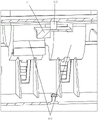
FIG. 3 is one of the perspective cross-sectional views of the present invention;
FIG. 4 is an enlarged view of portion A labeled in FIG. 3;
FIG. 5 is a schematic view of the air inlet path of the mist guiding device of the present invention;
FIG. 6 is a perspective view of a hidden portion of the housing of the present invention;
FIG. 7 is a second perspective cross-sectional view of the present invention;
FIG. 8 is an enlarged view of portion B labeled in FIG. 7;
FIG. 9 is an enlarged view of portion C labeled in FIG. 7;
FIG. 10 is a third perspective sectional view of the present invention;
fig. 11 is an enlarged view of a portion D marked in fig. 10.
Detailed Description
Embodiments of the present invention will be described in detail below with reference to the accompanying drawings.
As shown in fig. 1 to 11, the double-side blowing humidifier of the present embodiment includes a housing 1, a water storage chamber 12, an atomizing chamber 11 disposed below the water storage chamber 12 and communicated with the water storage chamber 12, and a mist outlet channel 13 communicated with the atomizing chamber 11 are further disposed in the housing 1, and a mist outlet 15 is disposed at an upper end of the mist outlet channel 13; the double-side blow humidifier further includes: the atomizing devices 2 are arranged in the atomizing cavity 11, are at least 2 groups in number, are arranged on the periphery of the mist outlet channel 13 at intervals and are used for atomizing water in the atomizing cavity 11; the mist guiding device 14 is arranged in the housing 1, is arranged corresponding to each atomization device 2, and is used for blowing air to guide the atomized water mist of each atomization device 2 to flow into the mist outlet channel 13 and then to be guided out through the mist outlet 15; according to the humidifier, at least two groups of atomization devices for atomizing water in the atomization cavity are arranged in the atomization cavity of the shell, so that the atomization amount of the humidifier is increased, the fog guide devices which correspond to the atomization devices one by one are arranged in the shell, the fog outlet efficiency of the humidifier is improved, the requirement of the humidifier for uniform fog outlet of various humidifiers with different fog outlet effects is met, the working time of the humidifier for enabling the surrounding environment to reach proper relative humidity is shortened, and the user experience is improved.
In this embodiment, in order to make the mist outlet effect be curtain-shaped and achieve a better visual effect, the cross-sectional shape of the mist outlet 15 is a long rectangle.
In this embodiment, a water-retaining noise-reducing structure 16 located right above each atomizing device 2 is disposed in the mist outlet channel 13, the water-retaining noise-reducing structure 16 includes an annular upper baffle 161 and an annular lower baffle 162, a plurality of flow deflectors 163 are disposed between the upper baffle 161 and the lower baffle 162 at intervals, and a spacing through hole 164 is disposed between two adjacent flow deflectors 163; the atomizing device is provided with the water retaining and noise reducing structure, so that when the atomizing device atomizes water in the atomizing cavity, water drops which are splashed and fly up are blocked by the lower baffle plate on the water retaining and noise reducing structure and then flow into the atomizing cavity, and therefore noise generated when the water drops fall back to the atomizing cavity is reduced, and the noise reducing effect is achieved; when the fog met during colder humidifier inner wall, can form the comdenstion water and down drop, the last baffle of manger plate structure can block the comdenstion water, and the comdenstion water flows back to the atomizing intracavity through the interval through-hole between the water conservancy diversion piece afterwards, avoids sending great sound because of the direct atomizing chamber that drops of comdenstion water, influences user's experience and feels.
In this embodiment, the flow deflectors 163 are disposed obliquely; further improving the efficiency of the condensed water flowing back to the atomizing cavity.
In this embodiment, a secondary water baffle 17 located above the water baffle and noise reduction structure 16 is further disposed in the mist outlet channel 13, the secondary water baffle 17 is provided with a plurality of through holes 171 and a mist outlet port 172, and an inclined deflector 173 is disposed on one side of the mist outlet port 172; the secondary water baffle blocks condensed water falling from a higher position in the humidifier, the condensed water flows back to the water retaining and noise reducing structure through the through hole, noise generated when the condensed water falls on the water retaining and noise reducing structure is reduced, and a double noise reducing effect is further formed; the secondary water baffle is provided with a mist outlet port, so that the blowing of the mist guiding device is not influenced, and the mist atomized by the atomizing device is guided to flow into the mist outlet channel; the inclined guide plate is arranged on one side of the mist outlet port, so that mist atomized by the atomizing device can uniformly flow into the mist outlet channel, and the mist outlet effect of the humidifier is uniform.
In this embodiment, the mist guiding device 14 includes a blower 141 disposed in the housing 1, an air inlet notch 142 is formed at the bottom of the housing 1 for the air inlet of the blower 141 to suck air, an air flow guiding channel 143 is further formed in the housing 1 and is communicated with the air outlet of the blower 141, and the air flow guiding channel 143 is communicated with the atomizing chamber 11 and is used for guiding the air flow blown out from the air outlet of the blower 141 to flow into the mist outlet channel 13.
In this embodiment, the bilateral blowing humidifier further includes a water guide cover 4 detachably connected to the top of the housing 1, the water guide cover 4 is provided with a water guide inclined plane 41, and a water guide cover mist outlet 42 corresponding to the mist outlet 15 is further formed on the water guide cover 4; by adopting the design, the assembly is convenient, and the assembly cost of the humidifier is reduced.
In this embodiment, the bottom of the atomization chamber 11 is provided with a water electrolysis sheet 5, the bottom of the atomization chamber 11 is provided with a mounting groove 111, and the water electrolysis sheet 5 is located in the mounting groove 111; the water electrolysis sheet is used for generating electrolysis reaction with the water in the atomization cavity to form electrolyzed water.
In this embodiment, 11 bottoms in atomizing chamber are equipped with and are used for detecting water level detector 6 of the interior water yield of atomizing chamber 11 prevents that the humidifier from continuing to carry out atomizing work under the condition that atomizing chamber lacks water, improves the security performance of humidifier.
In this embodiment, the outside of atomizing chamber 11 bottom be equipped with connecting portion 112, connecting portion 112 on be connected with humidity inductor 7, humidity inductor is used for detecting the inside humidity of atomizing chamber.
The technical contents of the present invention are further illustrated by the examples only for the convenience of the reader, but the embodiments of the present invention are not limited thereto, and any technical extension or re-creation based on the present invention is protected by the present invention. The protection scope of the utility model is subject to the claims.
Claims (10)
1. A double-side-blowing humidifier comprises a shell (1), and is characterized in that: a water storage cavity (12), an atomization cavity (11) which is arranged at the lower side of the water storage cavity (12) and communicated with the water storage cavity (12) and a mist outlet channel (13) which is communicated with the atomization cavity (11) are arranged in the shell (1), and a mist outlet (15) is formed in the upper end of the mist outlet channel (13);
the double-side blow humidifier further includes:
the atomizing devices (2) are arranged in the atomizing cavity (11), are at least 2 groups in number, are arranged on the periphery of the mist outlet channel (13) at intervals and are used for atomizing water in the atomizing cavity (11);
and the mist guiding device (14) is arranged in the shell (1), corresponds to each atomization device (2), and is used for guiding the atomized water mist of each atomization device (2) to flow into the mist outlet channel (13) and then to be guided out through the mist outlet (15).
2. The double-sided blowing humidifier according to claim 1, wherein: the cross section of the mist outlet (15) is in a long rectangular shape.
3. The double-sided blowing humidifier according to claim 1, wherein: be equipped with in fog outlet channel (13) and be located each structure (16) of making an uproar falls in manger plate directly over atomizing device (2), structure (16) of making an uproar falls in manger plate including being annular overhead gage (161) and being annular lower dog (162), overhead gage (161) and lower dog (162) between the interval be provided with a plurality of water conservancy diversion pieces (163), it is double-phase adjacent water conservancy diversion piece (163) are separated and are equipped with interval through-hole (164).
4. The double-sided blowing humidifier according to claim 3, wherein: the guide vanes (163) are obliquely arranged.
5. The double-sided blowing humidifier according to claim 3, wherein: still be equipped with in the fog passageway (13) and be located secondary breakwater (17) of structure (16) upside of making an uproar falls in the manger plate, a plurality of perforating holes (171) have been seted up on secondary breakwater (17) to and fog outlet opening (172) have still been seted up, fog outlet opening (172) one side is equipped with an inclined guide plate (173).
6. The double-sided blowing humidifier according to claim 1, wherein: lead fog device (14) including locating hair-dryer (141) in casing (1), casing (1) bottom is seted up and is supplied hair-dryer (141) air inlet inspiratory inlet slot mouth (142), still seted up in casing (1) with communicating air current guide passageway (143) in hair-dryer (141) gas outlet, air current guide passageway (143) with atomizing chamber (11) intercommunication, and be used for the guide air current that blows off hair-dryer (141) gas outlet flows in go out fog passageway (13).
7. The double-sided blowing humidifier according to claim 1, wherein: the bilateral blowing humidifier further comprises a water guide cover (4) detachably connected to the top of the shell (1), a water guide inclined plane (41) is arranged on the water guide cover (4), and a water guide cover mist outlet (42) corresponding to the mist outlet (15) is further formed in the water guide cover.
8. The double-sided blowing humidifier according to claim 1, wherein: atomizing chamber (11) bottom is equipped with water electrolysis piece (5), atomizing chamber (11) bottom is equipped with mounting groove (111), water electrolysis piece (5) be located in mounting groove (111).
9. The double-sided blowing humidifier according to claim 1, wherein: the bottom of the atomization cavity (11) is provided with a water level detector (6) for detecting the water quantity in the atomization cavity (11).
10. The double-sided blowing humidifier according to claim 1, wherein: the outside of atomizing chamber (11) bottom be equipped with connecting portion (112), connecting portion (112) on be connected with humidity inductor (7).
Priority Applications (1)
| Application Number | Priority Date | Filing Date | Title |
|---|---|---|---|
| CN202121924681.2U CN216011117U (en) | 2021-08-17 | 2021-08-17 | Bilateral air-blowing humidifier |
Applications Claiming Priority (1)
| Application Number | Priority Date | Filing Date | Title |
|---|---|---|---|
| CN202121924681.2U CN216011117U (en) | 2021-08-17 | 2021-08-17 | Bilateral air-blowing humidifier |
Publications (1)
| Publication Number | Publication Date |
|---|---|
| CN216011117U true CN216011117U (en) | 2022-03-11 |
Family
ID=80527892
Family Applications (1)
| Application Number | Title | Priority Date | Filing Date |
|---|---|---|---|
| CN202121924681.2U Active CN216011117U (en) | 2021-08-17 | 2021-08-17 | Bilateral air-blowing humidifier |
Country Status (1)
| Country | Link |
|---|---|
| CN (1) | CN216011117U (en) |
-
2021
- 2021-08-17 CN CN202121924681.2U patent/CN216011117U/en active Active
Similar Documents
| Publication | Publication Date | Title |
|---|---|---|
| CN113587295B (en) | Humidifier | |
| CN217161079U (en) | Atomizing footstock, atomizer and electronic atomization device | |
| CN216011117U (en) | Bilateral air-blowing humidifier | |
| CN210154005U (en) | Upper water adding humidifier | |
| CN215723836U (en) | Humidifier | |
| CN210220117U (en) | Humidifier | |
| CN210715180U (en) | Bladeless fan and air outlet device thereof | |
| CN210717933U (en) | Go out fog structure and humidifier | |
| CN210179822U (en) | Atomizing type equipment for generating negative ions | |
| CN210373926U (en) | Water tank assembly and humidifier | |
| CN214841372U (en) | Humidifier with improved air channel | |
| CN219328196U (en) | Humidifier silencing device and humidifier | |
| CN218864459U (en) | Silencing device and air humidifier | |
| CN218442610U (en) | Humidifying device | |
| CN214370699U (en) | Multistage atomizing humidifier | |
| CN210532603U (en) | Upper water adding humidifier | |
| CN218296184U (en) | Flow guide support of humidifier and humidifier | |
| CN215809023U (en) | Humidifier | |
| CN216079986U (en) | Range hood with air curtain device | |
| CN214891640U (en) | Humidifier pipeline formula air outlet | |
| CN113803822B (en) | Top-water-adding humidifier | |
| CN210569001U (en) | Fog gathering tower of humidifier | |
| CN217031472U (en) | Humidification device and fog gathering piece thereof | |
| CN213208088U (en) | Base structure and humidifier | |
| CN217209641U (en) | Humidifying device |
Legal Events
| Date | Code | Title | Description |
|---|---|---|---|
| GR01 | Patent grant | ||
| GR01 | Patent grant |