Atomizing type equipment for generating negative ions
Technical Field
The invention relates to ultrasonic atomization equipment capable of generating negative ions, in particular to atomization type equipment capable of reducing water on the surface of the equipment.
Background
Ultrasonic atomization is a method of using the basic principle of cavitation bubbles generated by ultrasonic high-frequency oscillation to break up atomized liquid such as water, thereby generating a drifting mist. Ultrasonic atomization equipment is very common in our daily life, and can be applied to air humidification, outdoor landscapes or negative ion preparation to form oxygen bars. The requirements on the mist making quantity of the ultrasonic atomization equipment are different according to different application scenes. For applications requiring a relatively large amount of mist, the most likely problems are condensation on the exterior of the device itself and water accumulation on the surface of the ground in the vicinity of the device. For this reason, a large number of related patent technologies have appeared in the prior art to solve such problems.
For example, the invention patent with application date of 2010, 4 and 29 and application number of 201010162828.9 named as 'humidifying fan' discloses a humidifying fan, which comprises a fan head, a supporting column of the fan head and a base, wherein the supporting column is supported on the base; atomizing chamber and water storage chamber that distributes about being provided with in the base, atomizing chamber and water storage chamber separate through the partition wall, the atomizing intracavity is provided with ultrasonic nebulizer, still be provided with on the base to increase atmospheric pressure's booster fan in the atomizing chamber and can with water in the water storage chamber supplyes the moisturizing pump in the atomizing chamber, the atomizing chamber top cap in atomizing chamber has out the fog mouth, and a port intercommunication of conveyer pipe goes out the fog mouth, and another port stretches the preceding position of fan head. The invention has the key point that the atomized steam is blown out again through the fan, so that the diffusion range of the atomized steam is expanded, the problem of water accumulation on the surface and the ground of the equipment is greatly reduced, and the equipment can be well used for humidifying the indoor environment, but the negative oxygen ions in the atomized steam are greatly destroyed by adopting the scheme.
For another example, application date is 2011 year 02 month 16 days, application number is 201120040658.7, the utility model discloses a utility model patent of "prevent ponding humidifier", discloses a prevent ponding humidifier, including base, water tank, water smoke emission pipe, be equipped with ultrasonic water smoke generation mechanism, air supply mechanism and control mechanism in the base, ultrasonic water smoke generation mechanism includes the basin, water smoke emission intraductal is equipped with the fender fog board, it forms the passageway of the tortuous water smoke circulation of return ring to block between fog board and the water smoke emission pipe. The utility model discloses to the humidifier ultrasonic atomization produces the great water smoke particle of many particle diameters among the prior art, is blown out the defect that easily condenses the drippage on the object behind the humidifier and forms "water film", provides a simple structure, shields the great water smoke particle of particle diameter, only blows out the tiny water smoke particle of particle diameter and has solved the ponding humidifier of preventing of "ponding" problem. Although this patent can reduce the water smoke particle of big granule and float out, but the board that keeps off fog in the main passageway of fog greatly reduced fogging efficiency and increased the helping hand of going out fog.
Therefore, further improvement is required in order to minimize the occurrence of condensation and to minimize the destruction of negative oxygen ions in the atomized vapor without affecting the atomizing efficiency.
Disclosure of Invention
According to the defects of the prior art, the invention provides an atomization device for generating negative ions, which comprises an atomization special container, wherein the atomization special container is used for containing atomized liquid and providing an ultrasonic atomization space for the atomized liquid, and an ultrasonic atomization generator for atomizing the liquid is arranged at the bottom of the atomization special container, and is characterized by further comprising an extension mist outlet channel which is flat and communicated with the ultrasonic atomization space, the extension mist outlet channel is positioned outside the atomization special container and extends in an obliquely upward direction, and the extension mist outlet channel has a width as viewed from the mist outlet direction: a height of at least 3: 1; the fog outlet structure comprises an outer extending fog outlet channel and an outer extending fog outlet channel, and is characterized by further comprising an upper wall body and a lower wall body which form the outer extending fog outlet channel, wherein when seen from the upper direction and the lower direction, the projection of the edge of the upper wall body at the fog outlet of the outer extending fog outlet channel is positioned in the outer extending fog outlet channel.
The flat shape means that when viewed from the fog outlet direction of the outward fog outlet channel, the width of the channel is far larger than the height, such as the width: the height ratio is set to be 20:1, 10:1, 5:1 or at least 3:1, etc., so that the outward extending fog-discharging channel can be communicated with the ultrasonic atomization space in a wider width range, the outward extending fog-discharging channel provides a wide channel for discharging atomized steam in the ultrasonic atomization space, and the atomized steam in the ultrasonic atomization space cannot be discharged in a concentrated manner only at a smaller part (such as the left part, the right part or the middle part). And secondly, the extension mist outlet channel can also provide mist to a wider external space range.
The outer extending mist outlet channel is located outside the special atomizing container, which means that the outer extending mist outlet channel can be directly connected or indirectly connected with the special atomizing container through other intermediate transition pipe sections, that is, the peripheral wall body of the outer extending mist outlet channel can be fixedly connected to the special atomizing container or other components such as an outer shell body to be mentioned later.
According to the technical scheme, the beneficial technical effects of the prior art are as follows:
1. the epitaxial mist outlet channel is flat, so that the atomized vapor in the ultrasonic atomization space is discharged without being concentrated to a fixed point (such as a left channel, a right channel or a middle channel), the flow of the atomized vapor can be shortened, the loss of negative ions caused by mutual interference caused by concentration of the atomized vapor in the mist outlet process is reduced, the atomized vapor can be provided to a wider space range, the diffusion space of the atomized vapor is enlarged, the loss of negative oxygen ions is further reduced, the diffusion of the negative ions to the surrounding space in a short time is facilitated, the concentration of the atomized vapor at the mist outlet part of the epitaxial mist outlet channel and in the space nearby the mist outlet channel can be relatively reduced, and the surface of the equipment and the ground nearby are not easy to condense water vapor.
2. Because the extending fog outlet channel extends in the upward inclined direction, compared with the scheme of spraying the fog out vertically upwards commonly used in the prior art, the invention can greatly reduce the sprayed fog steam from directly falling to the outer surface of the equipment, particularly the top surface of the equipment, thereby greatly reducing the dewing on the outer surface of the equipment; compared with the scheme of directly spraying the atomized steam from the wall of the atomizer in the horizontal direction in the prior art, the extended fog outlet channel has the structure of protruding extension, so that the atomized steam in the atomizing cavity can be smoothly discharged without turning, the fog outlet of the extended fog outlet channel can be far away from the equipment body, the atomized steam can be sprayed in the parabolic direction, the diffusion of the atomized steam in the air is facilitated, and the deposition at the peripheral edge of the fog outlet, particularly the edge of the lower wall body, can be greatly reduced, so that the formation of dripping is avoided.
3. According to the invention, as the projection of the edge of the upper wall body at the fog outlet of the extending fog outlet channel is positioned in the extending fog outlet channel when seen from the upper direction and the lower direction, the drip accumulated on the edge of the upper wall body can directly flow back into the special atomizing container by means of the extending fog outlet channel.
Above-mentioned improvement scheme not only can let atomizing vapour in the ultrasonic atomization space can discharge smoothly and diffusion range is wide, is difficult for the outward appearance of equipment, the dew formation of edge position under the fog outlet, can be favorable to preserving the anion that contains in the atomizing vapour in the discharge process in addition and also be favorable to anion to spread fast in the exterior space.
Further, the peripheral wall body forming the outward mist outlet passage may be connected to an outer sidewall body of the container dedicated for atomization. Wherein, the peripheral wall body at least comprises an upper wall body and a lower wall body which form the outward fog outlet channel, and even comprises a left wall body and a right wall body which form the outward fog outlet channel. Like this be provided with in the relatively longer scope of special container lateral wall body atomizes with extend the row's fog mouth that the fog passageway communicates, the atomizing vapour in the ultrasonic atomization space passes through it can enter fast and dispersedly to arrange the fog mouth extend the fog passageway, and need not concentrate on a fixed point (for example the left side, the right or middle) passageway discharge.
Further technical scheme can also be, be provided with transverse arrangement's first baffle in the special container of atomizing, be provided with at least one window of crossing wind on the first baffle, first baffle is used for letting the space that is located its outside form the air inlet duct and lets ultrasonic atomization space is located the inboard of first baffle. Like this, let outside entering air can pass with the help of inlet air channel the window of crossing enters into in the ultrasonic atomization space, force take out the atomizing vapour that exists in the ultrasonic atomization space can pass through discharge to outdoor in the outer fog passageway of going out.
A further technical scheme can also be that still be provided with transverse arrangement's second baffle in the special container of atomizing, second baffle and first baffle are relative arrangement around on longitudinal direction, be provided with at least one fog window on the second baffle, the second baffle is used for letting the space that is located its outside form out the fog main entrance, is located space between second baffle and the first baffle forms the ultrasonic atomization space, it communicates to extend out the fog passageway the play fog main entrance, it communicates to go out the fog main entrance the ultrasonic atomization space.
According to the above technical features, it is first defined that the mist outlet channel comprises not only the outward mist outlet channel but also the main mist outlet channel. Secondly, utilize second baffle and first baffle will the space that special container for atomizing contains separates left, well, right range go out fog main entrance, ultrasonic atomization space and air inlet duct to let outside entering air can pass with the help of air inlet duct the wind window enters into in the ultrasonic atomization space, force take out the atomizing vapour that exists in the ultrasonic atomization space and can pass through cross the fog window and enter into go out fog main entrance and then follow it is outdoor to discharge in the outer fog passageway. In addition, the second baffle can also be used for shielding large-particle water mist particles generated in the atomization process, and the large-particle water mist particles are reduced from directly falling out of the outward extending mist outlet channel and splashing to the object placing table top arranged below the atomization type equipment.
The special container for atomization is composed of a lower bottom container and a top cover arranged on the lower bottom container, and the first baffle and the second baffle are connected to the top cover or the lower bottom container; the air blower is arranged on the top cover or the side wall of the lower bottom container, and an air outlet of the air blower is communicated with the air inlet duct.
Further technical scheme can also be, special container for atomizing is the cuboid type of horizontal extension still be provided with at least one first division board in the ultrasonic atomization space, first division board will ultrasonic atomization space demarcation is two at least on horizontal left and right sides arrange and relatively independent sub-atomization space still be provided with in the play fog main entrance and correspond to the second division board of first division board, the second division board will play fog main entrance partition is two at least on horizontal left and right sides arrange and correspond to sub-atomization space's sub-play fog main entrance corresponds each sub-atomization space sets up a set of respectively atomizing ultrasonic generator. According to the technical scheme, the first partition plate and the second partition plate are arranged in the direction which is perpendicular to each other and forms a certain angle with the second baffle plate and the first baffle plate, for example, 90 degrees, so that each sub-atomization space works independently (atomizes and discharges atomized steam), the phenomenon that atomized steam in the sub-atomization spaces flows in series to form interference is reduced, the atomized steam can be directly discharged nearby, the loss of negative oxygen ions is reduced, and the atomization efficiency is improved. Secondly, the second partition plate not only partitions the main mist outlet channel but also can further extend and partition the extended mist outlet channel.
The technical scheme can be that one of the fog passing windows and one of the air passing windows are arranged in a front-back corresponding mode, and the first partition plate is located in the middle of the window position of the corresponding fog passing window and air passing window. Let like this from the air that gets into in one of them air inlet duct can flow into adjacent two in the sub-atomizing space, especially can also be when further technical scheme be, still be provided with in the air inlet duct corresponding to the third division board of first division board, the third division board will the air inlet duct is separated into at least two and is arranged about horizontal and correspond to the sub-air inlet duct of sub-atomizing space. That is, under the condition that a plurality of fans and sub air inlet channels thereof exist, the power of the fans can be uniformly distributed, all power is not required to be concentrated on one fan, so that the difficulty of positioning and shock resistance of the fans is increased, the number of working fans can be flexibly set according to the fog outlet quantity, and air in different sub air inlet channels can be balanced with each other.
The technical scheme is that the special atomization container is composed of a lower bottom container and a top cover assembly arranged on the lower bottom container, and further comprises a blower, the blower is arranged on the top cover or on the side wall of the lower bottom container, an air outlet of the blower is communicated with the air inlet channels, and a group of blowers is arranged corresponding to each sub air inlet channel respectively
The technical scheme is that the bottom space of the special atomization container for containing the atomized liquid is also provided with a fourth partition plate corresponding to the first partition plate, and the fourth partition plate divides the bottom space into at least two sub bottom spaces which are arranged horizontally and correspond to the sub atomization spaces. In this embodiment, the group of atomizing ultrasonic generators corresponding to each of the sub-atomizing spaces may be respectively disposed at the bottom of the corresponding sub-bottom space.
The technical scheme can also be that the atomizing device further comprises a liquid inlet pipe, an overflow pipe, a liquid level sensor and a liquid discharge pipe which are communicated with the special atomizing container, electromagnetic valves are respectively arranged on the liquid inlet pipe and the liquid discharge pipe, a slow flow net is arranged at an outlet of the liquid inlet pipe, and a liquid outlet of the overflow pipe is communicated with an outlet end of the electromagnetic valve on the liquid discharge pipe. Wherein, the slow flow net is in a net shape, so that the noise generated when the liquid flows into the special atomization container can be reduced. The overflow pipe is used for discharging liquid higher than a set liquid level, the liquid discharging process of the overflow pipe is not controlled by the electromagnetic valve, and the liquid entering the overflow pipe can cross the electromagnetic valve to be discharged. According to the scheme, the automatic feeding of atomized liquid can be realized, the residual atomized liquid can be discharged periodically, the liquid is prevented from being stored in the special atomization container for a long time and bacteria are prevented from breeding when the liquid is not used, and the damage to the equipment can be reduced.
Further technical scheme can also be, still include the shell body, special container of atomizing is acceptd in the shell body be provided with on the perpendicular lateral wall of shell body and dodge the hole, dodge the hole be the adaptation in the rectangular form of epitaxial fog passageway, the fog passageway of extending extends dodge the hole.
The vertical side wall of the outer shell is an outer side wall body which faces to the activity space of a user and is perpendicular to the horizontal plane. The avoiding hole is in a long strip shape, namely the width of the avoiding hole is far greater than the height of the avoiding hole.
Wherein, in order to realize the fog passageway of extending extends dodge the hole, specific structure can the fog passageway of extending goes up the wall edge combination and is in on the inside wall of shell body or overlap joint reach dodge the drill way perisporium at hole place or further extend and exceed dodge the drill way perisporium of hole, and the lower wall body edge protrusion of the fog passageway of extending is in the shell body wall body that dodges the hole place. This ensures that the mist discharged from the outer mist outlet channel is reliably released into the outer space without flowing back into the outer housing through the gaps between the upper and lower wall edges and the outer housing. In addition, because the outward extending fog outlet channel extends in the upward inclined direction, the sprayed atomized steam can not easily contact the outer shell positioned above the upper wall body to cause the problem of condensation by virtue of the inclined motion force of the atomized steam; even if a small amount of dew condensation droplets occur on the outer shell located above the upper wall body, the droplets naturally flow back into the extended mist outlet passage without falling to the ground, particularly when the edge of the upper wall body is disposed flush with the outer shell; and because the edge of the lower wall body protrudes out of the wall body of the outer shell body where the avoidance hole is located, atomized steam sprayed from the outward fog outlet channel cannot easily contact the outer shell body located below the outward fog outlet channel and further dew is formed. The proposal better solves the problems that the periphery of the spray opening is easy to condense and form dripping dew.
Further technical scheme can also be, the shell body transversely extends in the left and right direction and is the pillow type, dodge the hole and reach it also sets up along transversely extending to extend out the fog passageway outward.
The further technical scheme can also be that the device further comprises a floor type support frame, and the outer shell is installed on the support frame.
The technical scheme can also be that the device further comprises an environment detection module and a control circuit, wherein the environment detection module is arranged on the outer shell and is used for acquiring the environment parameters of the application environment and sending the environment parameter information to the control circuit. Wherein, the environmental parameter information can be parameter values such as negative oxygen ion concentration, PM2.5, humidity and the like. The control circuit can control the next operation of the atomization type equipment according to the environmental parameter information, for example, when the humidity value is lower than a set value, the ultrasonic atomization generator is started to work, otherwise, the ultrasonic atomization generator is stopped to work.
The present invention, owing to its features and advantages, can be applied to atomizing devices.
Drawings
FIG. 1 is a schematic perspective view of an atomizing apparatus for generating negative ions to which the present invention is applied;
FIG. 2 is a schematic structural diagram of a top view of the atomizing device for generating negative ions;
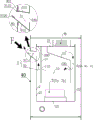
FIG. 3 is a schematic view of the cross-sectional structure taken along the line A-A (longitudinal direction) in FIG. 2;
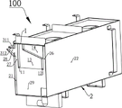
fig. 4 is a schematic perspective view of the container 100 for exclusive use in atomization, in which a part of the wall is cut away for clarity;
fig. 5 is a schematic perspective view of the lower base container 2, in which the upper wall 311 forming the outer mist outlet passage 31 is omitted;
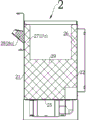
FIG. 6 is a schematic cross-sectional view in the direction B-B of FIG. 5, with the shapes of the divider plates (26, 27, 28, 29) shown filled with lines for clarity;
FIG. 7 is a schematic structural view of the atomizing device viewed from the mist outlet direction of the outward extending mist outlet channel (i.e., the direction F shown in FIG. 3);
fig. 8 is a schematic perspective view of the cover combination member formed by the top cover 1, the second baffle 11, the first baffle 12, and the like;
FIG. 9 is a perspective view of the cover combination of FIG. 8 in another orientation;
FIG. 10 is a front view in elevation of the cover combination of FIG. 8;
fig. 11 is a schematic perspective view of the atomizing device for generating negative ions after the outer shell 4 is removed;
fig. 12 is a schematic perspective view of the atomizing device for generating negative ions from another view direction after the outer housing 4 is removed.
Detailed Description
As shown in fig. 1, fig. 2, fig. 3 and fig. 7, an atomization device for generating negative ions comprises an atomization special container 100, the atomization special container 100 is used for containing atomized liquid and providing an ultrasonic atomization space 10 for the atomized liquid, and an ultrasonic atomization generator 7 for atomizing the liquid is arranged at the bottom of the atomization special container 100; the special atomizing container 100 is characterized by further comprising an outward extending atomizing channel 31 which is flat and communicated with the ultrasonic atomizing space 10, wherein the outward extending atomizing channel 31 is positioned outside the special atomizing container 100 and extends in an inclined upward direction; the width W of the epitaxial haze-discharging channel 31, as viewed from the haze-discharging direction of the epitaxial haze-discharging channel: a height H of at least 3: 1; the fog nozzle also comprises an upper wall body 311 and a lower wall body 312 which form the outward fog outlet channel 31, and the projection of the edge 3110 of the upper wall body at the fog outlet of the outward fog outlet channel 31 is positioned in the outward fog outlet channel 31 when seen in the vertical direction.
The structure of the atomizing device for generating negative ions to which the technical solution of the present invention is applied will be further described with reference to the accompanying drawings.
As shown in fig. 1, the atomization apparatus includes an atomization specific container 100, and the atomization specific container 100 has a laterally extending rectangular parallelepiped shape. The container 100 dedicated for atomization is used for containing liquid to be atomized and providing an ultrasonic atomization space 10 for the liquid to be atomized. The container 100 for atomization is composed of a lower bottom container 2 and a top cover 1 arranged on the lower bottom container.
As shown in fig. 4, 5, 6, 8, 9 and 10, the lower base container 2 includes front and rear lateral side walls (21, 22), left and right longitudinal side walls (23, 24) and a bottom wall 25 connected to the lateral side walls (21, 22) and the longitudinal side walls (23, 24), and the ultrasonic atomization generator 7 for atomizing a liquid is provided on the bottom wall 25. Extension edges 200 are arranged on the top of the front and rear transverse side wall bodies (21, 22) and the left and right longitudinal side wall bodies (23, 24), and the outer edge of the top cover 1 is overlapped on the extension edges 200. A sealing member is provided between the outer edge of the top cover 1 and the extension edge 200 to prevent the mist from leaking out of the gap therebetween. Two first baffles 12 and two second baffles 11 are arranged on the top cover 1 in a front-back opposite manner in the longitudinal direction and extend in the transverse direction. Of course, in other embodiments, the second baffle 11 and the first baffle 12 may also be attached to the lower base container 2. At least one relatively wide fog passing window is arranged on the second baffle plate 11, and at least one relatively wide air passing window is arranged on the first baffle plate 12. In the present embodiment, the scheme of providing two through-mist windows (110, 110a) and two through-wind windows (120, 120a) corresponds to three sub-atomization spaces (10a, 10b, 10c) to be mentioned below.
The first and second baffles 12 and 11 extend into the lower base container 2 from the top to the bottom, as viewed in longitudinal cross-section as shown in fig. 3. A main mist outlet channel 32 is formed on the outer side of the second baffle 11, and in fact, the second baffle 11, the front transverse sidewall 21 and the top cover 1 located on the outer side of the second baffle 11 form the main mist outlet channel 32 together by utilizing the structure that the second baffle 11 extends into the lower bottom container 2; the upper part of the front transverse sidewall body 21 is provided with a mist discharge port 320 communicated with the main mist outlet channel 32, and the mist discharge port 320 is long and transversely arranged. Of course, in other embodiments, the mist discharge port 320 may also be disposed on the top cover 1. An air inlet duct 5 is formed on the outer side of the first baffle plate 12, and in fact, the first baffle plate 12 extends into the lower bottom container 2, so that the first baffle plate 12, the rear transverse side wall body 22 and the top cover 1 located on the outer side of the first baffle plate form the air inlet duct 5 together, and the space located between the second baffle plate 11 and the first baffle plate 12 forms the ultrasonic atomization space 10. The main mist outlet channel 32 communicates with the ultrasonic atomizing space 10. The top cover 1 is provided with a blower 6, an air outlet of the blower 6 is communicated with the air inlet duct 5, and in other embodiments, the blower 6 may be arranged on the upper portion of the rear transverse sidewall 22. Thus, the air entering from the air inlet duct 5 passes through the air passing windows (120, 120a) and enters the ultrasonic atomization space 10, carries the atomized steam out of the mist passing windows (110, 110a) and enters the main mist outlet channel 32, and is discharged through the mist discharge port 320. According to the technical structure, the main mist outlet channel 32 is formed on the outer side of the second baffle plate 11, and the air inlet duct 5 is formed on the outer side of the first baffle plate 12, so that the internal structure of the special atomizing container 100 is greatly simplified; secondly, because the fog discharge port 320 is in a strip shape and is transversely arranged, the atomized steam can be directly discharged nearby, and the discharge flow of the atomized steam is shortened, so that the atomization fogging efficiency is improved and the loss of negative oxygen ions is greatly reduced in the environment of large fog amount atomization. Secondly, the second baffle 11 can shield large water droplets generated in the atomization process, and the large water droplets are prevented from being directly discharged from the mist discharge port 320 to the outside of the special atomization container 100 and being splashed to a storage table surface arranged below the atomization device.
Further, as shown in fig. 5 and 7, the container 100 for atomizing also includes a section of outward extending mist outlet channel 31 extending from the container 100 for atomizing and communicating with the mist outlet 320, and the outward extending mist outlet channel 31 and the main mist outlet channel 32 are communicated with each other to form the mist outlet channel 3. The outward extending mist outlet channel 31 is flat, and the outward extending mist outlet channel 31 is located outside the special atomizing container 100 and extends along the lateral side wall 21 of the special atomizing container 100 in the lateral extending direction and extends in the oblique upward direction. The width W of the epitaxial mist outlet channel 31, as viewed from the mist outlet direction of the epitaxial mist outlet channel 31 (i.e., the direction F shown in fig. 3): the height H is at least 3:1, such as 20:1, 10:1, 5:1, and the like. Thus, the width of the outward mist outlet channel 31 is much larger than the height, so that the outward mist outlet channel 31 can communicate with the ultrasonic atomization space 10 in a relatively wide width range on the lateral side wall 21 of the container 100 dedicated for atomization. The extended mist outlet channel 31 is flat, so that the atomized vapor in the ultrasonic atomization space 10 is discharged without being concentrated to a fixed point (such as a left channel, a right channel or a middle channel), the flow of the atomized vapor can be shortened, the loss of negative ions caused by mutual interference due to concentration of the atomized vapor in the mist outlet process is reduced, the atomized vapor can be provided to a wider space range, the diffusion space of the atomized vapor is enlarged, the loss of negative oxygen ions is further reduced, the diffusion of the negative ions to the surrounding space in a short time is facilitated, the concentration of the atomized vapor at the mist outlet part of the extended mist outlet channel 31 and the surrounding space can be relatively reduced, and the surface of the device and the surrounding ground are not easy to condense the vapor. Secondly, because the extending fog outlet channel 31 extends in the upward inclined direction, compared with the scheme of spraying vertically upwards commonly used in the prior art, the invention can greatly reduce the sprayed atomized steam directly falling on the outer surface of the equipment, particularly the top surface of the equipment, thereby greatly reducing the dewing on the outer surface of the equipment; compared with the scheme of directly spraying the atomized steam from the wall of the atomizer in the horizontal direction in the prior art, the extended fog outlet channel 31 has a protruding and extending structure, so that the atomized steam in the atomizing cavity can be smoothly discharged without turning, the fog outlet can be far away from the equipment body, the atomized steam can be sprayed in a parabolic direction, the atomized steam can be favorably diffused in the air, and the deposition at the peripheral edge of the fog outlet, particularly the edge of the lower wall body 312, can be greatly reduced, so that the formation of the dripping dew is avoided.
And also includes peripheral walls forming the outer mist outlet passage 31, i.e., an upper wall 311, a lower wall 312, and left and right side walls. The peripheral wall of the outward mist outlet passage 31 is directly connected and fixed to the lateral side wall 21 of the container 100 for exclusive atomization. The projection of the upper wall edge 3110 at the mist outlet of the outward mist outlet channel 31 is located in the outward mist outlet channel 31, as seen in the up-down direction, so that the droplets accumulated on the upper wall edge 3110 can flow back into the dedicated atomizing container 100 directly via the outward mist outlet channel 31. Of course, as another embodiment, the outward extending mist outlet channel 31 may also be fixedly connected to the outer shell 4 to be discussed below to directly or indirectly communicate with the mist outlet 320 and the main mist outlet channel 32, as long as the outward extending mist outlet channel 31 and the main mist outlet channel 32 are ensured to communicate with each other to form the mist outlet channel 3.
As shown in fig. 1 and 3, the atomizing device further includes an outer housing 4 and a floor-type support frame (not shown), and the outer housing 4 is mounted on the support frame. The outer shell 4 transversely extends in the left-right direction to form a pillow shape. The special container 100 for atomization is accommodated in the outer shell 4, a avoiding hole 401 is formed in the vertical side wall 40 of the outer shell 4, the avoiding hole 401 is adaptive to the long strip shape of the outward fog outlet channel 31, and the avoiding hole 401 reaches the outward fog outlet channel 31 and is also arranged along the transverse extension. The extending mist outlet channel 31 extends out of the avoiding hole 401. The specific structure is that the left and right side wall body edges (3130, 3140) of the outward extending fog outlet channel 31 extend beyond the orifice peripheral wall of the avoidance hole 401, and the upper wall body edge 3110 of the outward extending fog outlet channel 31 is lapped on the orifice peripheral wall where the avoidance hole 401 is located. Of course, in other embodiments, the left and right side wall edges (3130, 3140) of the outward fog outlet channel 31 may be bonded to the inner side wall of the outer shell 4 or overlapped to the orifice peripheral wall where the avoidance hole 401 is located, and a sealant may be used to seal the bonding or overlapping position; the upper wall edge 3110 of the outward mist outlet channel 31 is bonded to the inner side wall of the outer housing 4 or extends further beyond the orifice peripheral wall of the escape hole 401. This ensures that the mist discharged from the outward mist discharge passage 31 is reliably released into the external space without flowing backward into the outer case 4 from the left and right side wall edges (3130, 3140) and the gap between the upper wall edge 3110 and the outer case 4; especially when the left and right side wall body edges (3130, 3140), the upper wall body edge 3110 of the extending fog outlet channel 31 are set to be combined on the inner side wall of the outer shell 4 or overlap the orifice peripheral wall where the avoiding hole 401 is located, because the extending fog outlet channel 31 is flat and almost covers the whole width range of the exhausted atomized steam, the protruding heights of the left and right side wall body edges (3130, 3140) and the upper wall body edge 3110 do not exceed the outer surface of the outer shell 4 where the avoiding hole 401 is located and are located on the vertical side wall 40 of the outer shell 4, therefore, the condensed water formed on the outer surface of the outer shell 4 above the left and right side wall body edges (3130, 3140) and the upper wall body edge 3110 can directly flow back into the extending fog outlet channel 31. According to the above-mentioned solution, since the extended mist outlet channel 31 extends in an upward inclined direction, the sprayed mist can not easily contact the outer shell 4 above the upper wall 311 and cause a condensation problem by virtue of the inclined movement force of the mist itself; even if a small amount of dew condensation droplets occur on the outer shell 4 located above the upper wall 311, particularly when the edge of the upper wall 311 is disposed flush with the outer shell 4, the droplets naturally flow back into the outer mist outlet passage 31 without dropping to the ground; since the lower wall edge 3120 protrudes from the wall of the outer shell 4 where the avoidance hole 401 is located, the mist sprayed obliquely from the outward mist outlet channel 31 does not easily contact the outer shell 4 located below the outward mist outlet channel 31 and form condensation. The proposal better solves the problems that the periphery of the spray opening is easy to condense and form dripping dew.
As shown in fig. 4 to 10, in order to further reduce the loss of negative oxygen ions, two longitudinally arranged first partition plates (13, 13a) are further provided in the ultrasonic atomization space 10. The first dividing wall (13, 13a) is arranged at an angle of substantially 90 ° to the second baffle 11 and the first baffle 12. The first partition plates (13, 13a) are connected between the top cover 1 and the second baffle plate 11 and the first baffle plate 12 to divide the ultrasonic atomization space 10 into three sub-atomization spaces (10a, 10b, 10c) which are arranged left and right in the transverse direction and are relatively independent. A second partition plate (27, 27a) corresponding to the first partition plate (13, 13a) is also provided in the mist outlet main passage 32. The second partition plate (27, 27a) is connected between the front lateral side wall body 21 of the lower base container 2 and the second partition plate 11 to divide the main mist outlet passage 32 into three sub main mist outlet passages (not shown) arranged laterally left and right and corresponding to the sub mist generating spaces (10a, 10b, 10 c). In addition, a second sub-partition plate (28, 28a) which is an extension of the second partition plate (27, 27a) is further provided in the outer mist outlet passage 31, and the second sub-partition plate (28, 28a) is connected between the upper wall body 311 and the lower wall body 312 to divide the outer mist outlet passage 31 into three sub-outer mist outlet passages (31a, 31b, 31c) which are arranged left and right in the lateral direction and correspond to the sub-atomizing spaces (10a, 10b, 10 c). The three sub-mist outlet main channels and the three sub-outer mist outlet channels (31a, 31b and 31c) are respectively communicated correspondingly to form three sub-mist outlet channels. The second partition plates (27, 27a) and the second sub-partition plates (28, 28a) may be in a split structure, but may be in a front-back abutting connection, or may be in an integrally formed structure. In another embodiment, the second sub-partition plates (28, 28a) may be omitted, which does not significantly affect the loss of negative oxygen ions. A group of atomizing ultrasonic generators (7, 7a, 7b) is respectively arranged corresponding to each sub-atomizing space (10a, 10b, 10 c). According to the above technical solution, the first partition plate (13, 13a), the second partition plate (27, 27a), the second sub-partition plate (28, 28a) and the second baffle plate 11 and the first baffle plate 12 are arranged in a certain angle, for example, in the mutually perpendicular directions of 90 degrees, so that each of the sub-atomization spaces (10a, 10b, 10c) works independently (atomization, discharge of atomized steam), and the atomized steam in the sub-atomization spaces (10a, 10b, 10c) is not disturbed by the cross flow of atomized steam, and the atomized steam can be directly discharged nearby, thereby reducing the loss of negative oxygen ions and improving atomization efficiency.
As shown in fig. 6 to 10, the fog passing window 110 and the air passing window 120 are arranged in front and back correspondence, the fog passing window 110a and the air passing window 120a are arranged in front and back correspondence, and the first partition plates (13, 13a) are respectively located at the middle positions of the window portions of the fog passing window 110 and the air passing window 120, and the fog passing window 110a and the air passing window 120a which are arranged in correspondence. Third partition plates (14, 26) corresponding to the first partition plate 13 and third partition plates (14a, 26a) corresponding to the first partition plate 13a are further provided in the intake duct 5. Wherein the third dividing plate (14, 14a) is connected between the top cover 1 and the first baffle plate 12, and the third dividing plate (26, 26a) is connected to the rear lateral side wall body 22 of the lower base container 2 and is connected to a fourth dividing plate (29, 29a) to be discussed below, respectively. The third partition plates (14, 26, 14a, 26a) divide the air inlet duct 5 into three sub air inlet ducts (5a, 5b, 5c) which are arranged in the transverse direction left and right and correspond to the sub atomization spaces (10a, 10b, 10c), and a group of blowers (6, 6a, 6b) are respectively arranged corresponding to each sub air inlet duct (5a, 5b, 5 c). That is, under the condition that a plurality of air blowers (6, 6a, 6b) and sub air inlet channels (5a, 5b, 5c) thereof exist, the power of the air blowers (6, 6a, 6b) can be uniformly distributed, all power is not required to be concentrated on one air blower, so that the difficulty of positioning and shock resistance of the air blower is increased, the number of working air blowers can be flexibly set according to the size of mist outlet quantity, and the air in different sub air inlet channels (5a, 5b, 5c) can be balanced with each other.
As shown in fig. 4, 5 and 6, a fourth partition plate (29, 29a) corresponding to the first partition plate (13, 13a) is further provided in the bottom space of the lower bottom container 2 for containing the atomized liquid, and the fourth partition plate (29, 29a) is respectively provided on the lower bottom container 2 and connected to the second partition plate (27, 27a) and the third partition plate (26, 26 a). The fourth dividing wall (29, 29a) divides the bottom space into three sub-bottom spaces (20, 20a, 20b) arranged laterally left and right and corresponding to the sub-atomization spaces (10a, 10b, 10 c). The atomizing ultrasonic generators (7, 7a, 7b) provided corresponding to each of the sub-atomizing spaces (10a, 10b, 10c) are respectively provided at the bottom of the corresponding sub-bottom space (20, 20a, 20 b).
In a practical arrangement, the number of the first partition plates (13, 13a), the second partition plates (27, 27a), the second partition plates (28, 28a), the third partition plates (14, 14a, 26a) and the fourth partition plates (29, 29a) may be one, two or more, and at least two of the sub-atomizing spaces, the sub-mist outlet passages, the sub-air inlet ducts and the sub-bottom spaces may be formed respectively according to the transverse length of the container 100 dedicated for atomizing. The first partition plate (13, 13a), the second partition plate (27, 27a, 28a), the third partition plate (14, 14a, 26a), and the fourth partition plate (29, 29a) may be formed as an integrally formed plate body, or may be formed as a separate body.
As shown in fig. 11 and 12, the atomization apparatus for generating negative ions further includes a liquid inlet pipe 73, an overflow pipe 71, a liquid level sensor (not shown in the figures), and a liquid outlet pipe 72, which are communicated with the special atomization container 100, wherein the liquid inlet pipe 73 and the liquid outlet pipe 72 are respectively provided with an electromagnetic valve (not shown in the figures), and an outlet of the liquid inlet pipe 73 is provided with a slow flow network (not shown in the figures). The overflow pipe 71 is used for discharging liquid above a set liquid level, and according to a general method, a liquid outlet of the overflow pipe 71 can be communicated with an outlet end of a solenoid valve on the liquid discharge pipe 72, the liquid discharge process of the overflow pipe 71 is not controlled by the solenoid valve, and the liquid entering the overflow pipe can be discharged out through the solenoid valve. According to the scheme, the atomized liquid can be automatically added, the residual atomized liquid can be discharged periodically, the liquid is prevented from being stored in the special atomization container 100 for a long time and bacteria are prevented from breeding when the special atomization container is not used, and the damage to the equipment can be reduced.
In order to optimize the intelligent management of the atomization device, the atomization device further comprises an environment detection module (not shown in the figure) and a control circuit (not shown in the figure), wherein the environment detection module is arranged on the outer shell 4 and is used for acquiring the environment parameters of the application environment and sending the environment parameter information to the control circuit. Wherein, the environmental parameter information can be parameter values such as negative oxygen ion concentration, PM2.5, humidity and the like. The control circuit can control the next operation of the atomization type equipment according to the environmental parameter information, for example, when the humidity value is lower than a set value, the ultrasonic atomization generator is started to work, otherwise, the ultrasonic atomization generator is stopped to work.