CN215998950U - Nut sheet nut hole chamfering machine - Google Patents

Nut sheet nut hole chamfering machine Download PDF

Info

Publication number
CN215998950U
CN215998950U CN202121400907.9U CN202121400907U CN215998950U CN 215998950 U CN215998950 U CN 215998950U CN 202121400907 U CN202121400907 U CN 202121400907U CN 215998950 U CN215998950 U CN 215998950U
Authority
CN
China
Prior art keywords
side wall
fixedly connected
nut
chamfering machine
workbench
Prior art date
Legal status (The legal status is an assumption and is not a legal conclusion. Google has not performed a legal analysis and makes no representation as to the accuracy of the status listed.)
Active
Application number
CN202121400907.9U
Other languages
Chinese (zh)
Inventor
赵庆锋
王新华
赵庆辉
Current Assignee (The listed assignees may be inaccurate. Google has not performed a legal analysis and makes no representation or warranty as to the accuracy of the list.)
Dongtai Gujie Metal Products Co ltd
Original Assignee
Weihai Haofeng Precision Electronics Co ltd
Priority date (The priority date is an assumption and is not a legal conclusion. Google has not performed a legal analysis and makes no representation as to the accuracy of the date listed.)
Filing date
Publication date
Application filed by Weihai Haofeng Precision Electronics Co ltd filed Critical Weihai Haofeng Precision Electronics Co ltd
Priority to CN202121400907.9U priority Critical patent/CN215998950U/en
Application granted granted Critical
Publication of CN215998950U publication Critical patent/CN215998950U/en
Active legal-status Critical Current
Anticipated expiration legal-status Critical

Links

Images

Landscapes

  • Cleaning In General (AREA)

Abstract

本实用新型公开了一种螺母片螺母孔倒角机,包括工作台,所述工作台上侧壁固定连接有台柱,所述台柱上侧壁固定连接有电机,所述台柱的侧壁转动连接有往复丝杠,所述电机输出轴固定连接有连杆,所述连杆远离电机的输出轴一端固定连接有转动刀头,所述连杆通过皮带与往复丝杠传动连接,所述工作台上侧壁固定连接有固定块,所述往复丝杠侧壁螺纹连接有限位块,所述限位块的侧壁固定连接有刷杆。本实用新型能够在倒角的同时清理工作台表面的碎屑,既节省了时间,又减轻了工人们的劳动量,并且收集后的粉末会被排入水箱内避免了空气的污染。
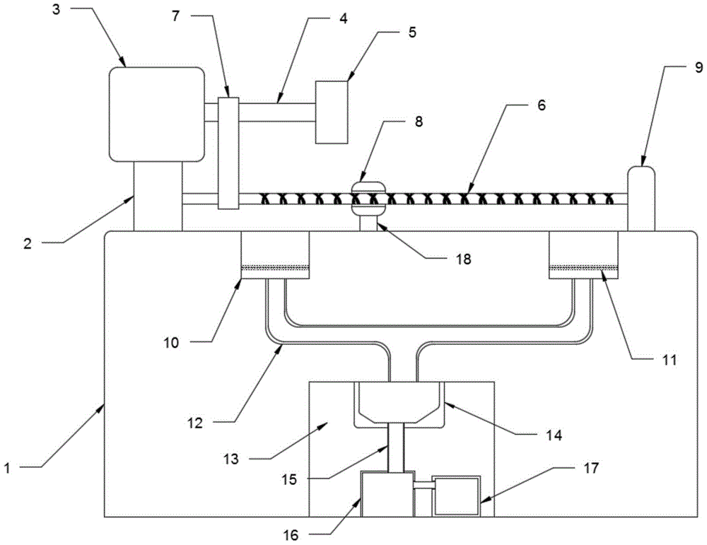
Figure 202121400907

The utility model discloses a nut sheet nut hole chamfering machine, comprising a worktable, a table column is fixedly connected to the upper side wall of the table column, a motor is fixedly connected to the upper side wall of the table column, and the side wall of the table column is rotatably connected There is a reciprocating screw, a connecting rod is fixedly connected to the output shaft of the motor, and a rotating cutter head is fixedly connected to one end of the connecting rod away from the output shaft of the motor. The connecting rod is connected to the reciprocating screw through a belt. The upper side wall is fixedly connected with a fixing block, the side wall of the reciprocating screw is threadedly connected with a limit block, and the side wall of the limit block is fixedly connected with a brush rod. The utility model can clean the debris on the surface of the worktable while chamfering, which not only saves time, but also reduces the labor of workers, and the collected powder will be discharged into the water tank to avoid air pollution.

Figure 202121400907

Description

Nut sheet nut hole chamfering machine
Technical Field
The utility model relates to the technical field of nut processing equipment, in particular to a nut sheet nut hole chamfering machine.
Background
The nut is a nut, and is screwed together with a bolt or a screw rod to play a role in fastening, and one element which is necessary for all production and manufacturing machines is divided into carbon steel, stainless steel, non-ferrous metal (such as copper) and other types according to different materials.
The nut piece is punching the back, need carry out the chamfer to the both sides in nut hole, have a large amount of pieces after the chamfer and drop at the workstation, workman often need stop the machine and then clear up the piece on the workstation, can consume a large amount of time during the clearance, also can consume people's physical power, and the piece that is located the corner department is omitted easily, and all pieces on the workstation all can be abandoned as the waste material, not only influence the efficiency of work, and also can cause certain waste, so need design a nut piece nut hole beveler.
SUMMERY OF THE UTILITY MODEL
The utility model aims to solve the defects in the prior art and provides a nut piece and nut hole chamfering machine.
In order to achieve the purpose, the utility model adopts the following technical scheme:
the utility model provides a nut piece nut hole beveler, includes the workstation, lateral wall fixedly connected with pillar on the workstation, lateral wall fixedly connected with motor on the pillar, the lateral wall of pillar rotates and is connected with reciprocal lead screw, motor output shaft fixedly connected with connecting rod, the output shaft one end fixedly connected with who the motor was kept away from to the connecting rod rotates the tool bit, the connecting rod passes through the belt and is connected with reciprocal screw drive, lateral wall fixedly connected with fixed block on the workstation, reciprocal lead screw lateral wall threaded connection has the stopper, the lateral wall fixedly connected with brush-holder stud of stopper, the one end that the pillar was kept away from to reciprocal lead screw rotates with the fixed block to be connected, be equipped with collection mechanism on the workstation.
Preferably, collect mechanism including setting up two filter tanks of lateral wall on the workstation, the workstation downside wall is equipped with the collecting vat, two the filter tank downside wall intercommunication is equipped with Y type pipe, the one end intercommunication that two filter tanks were kept away from to Y type pipe is equipped with the collection box collect box fixed connection at the interior top of collecting vat, collecting vat bottom fixedly connected with dust catcher, the collection box passes through the inlet end intercommunication of pipe with the dust catcher, collecting vat bottom fixedly connected with water tank, the end of giving vent to anger of dust catcher passes through pipe and water tank intercommunication.
Preferably, filter screens are arranged in the two filter tanks, and inclined planes are arranged at the bottoms of the collecting boxes.
Preferably, a box door is arranged on the side wall of the workbench, and a rubber pad is arranged on the side wall of the box door, which is in contact with the collecting groove.
Preferably, the Y-shaped conduit is made of plastic, and the conduit is made of plastic.
Preferably, the brush rod is attached to the upper side wall of the workbench, and bristles are arranged on the contact surface of the brush rod and the workbench.
The utility model has the following beneficial effects:
1. the brush rod is driven by the reciprocating screw rod to reciprocate on the surface of the workbench, so that chamfering work can be performed while debris on the surface of the workbench is cleaned, time specially used for cleaning the debris on the surface of the workbench is saved, physical strength of workers for cleaning the debris is saved, and the debris at the corners can be cleaned;
2. the dust collector is provided with the filter tank and the filter screen, so that cleaned debris can be filtered, large waste materials which can be utilized can be remained in the filter tank and can be recycled, and small broken foam cannot be reused, and the small broken foam can be sucked into the collecting box from the filter tank through the Y-shaped guide pipe under the action of the dust collector and then is discharged into the water tank, so that not only can the debris be collected, but also the powder waste materials can be prevented from floating into air to influence the air quality.
Drawings
Fig. 1 is a schematic structural view of a nut piece and nut hole chamfering machine provided by the utility model;
fig. 2 is a top view of a nut piece and nut hole chamfering machine according to the present invention;
fig. 3 is a front view of a nut piece and nut hole chamfering machine according to the present invention.
In the figure: 1 workbench, 2 columns, 3 motors, 4 connecting rods, 5 rotating tool bits, 6 reciprocating lead screws, 7 belts, 8 limiting blocks, 9 fixing blocks, 10 filter tanks, 11 filter screens, 12Y-shaped guide pipes, 13 collecting tanks, 14 collecting boxes, 15 guide pipes, 16 dust collectors, 17 water tanks, 18 brush rods and 19 box doors.
Detailed Description
The technical solutions in the embodiments of the present invention will be clearly and completely described below with reference to the drawings in the embodiments of the present invention, and it is obvious that the described embodiments are only a part of the embodiments of the present invention, and not all of the embodiments.
Referring to fig. 1-3, a nut hole chamfering machine comprises a workbench 1, a table post 2 is fixedly connected to the side wall of the workbench 1, a motor 3 is fixedly connected to the side wall of the table post 2, a reciprocating screw 6 is rotatably connected to the side wall of the table post 2, an output shaft of the motor 3 is fixedly connected with a connecting rod 4, one end of the connecting rod 4, far away from the output shaft of the motor 3, is fixedly connected with a rotary cutter head 5, the connecting rod 4 is in transmission connection with the reciprocating screw 6 through a belt 7, when the motor 3 works, the connecting rod 4 is driven to rotate, the reciprocating screw 6 is driven to rotate through the belt 7, a brush rod 18 is driven to reciprocate left and right, the surface of the workbench 1 is further cleaned, a fixed block 9 is fixedly connected to the side wall of the workbench 1, a limit block 8 is in threaded connection with the side wall of the reciprocating screw 6, a brush rod 18 is fixedly connected to the side wall of the limit block 8, and the brush rod 18 is attached to the upper side wall of the workbench 1, the brush rod 18 is provided with brush hair on the contact surface with the workbench 1, the brush hair can clean the surface of the workbench 1, one end of the reciprocating screw rod 6 far away from the table post 2 is rotatably connected with the fixed block 9, the workbench 1 is provided with a collecting mechanism, the collecting mechanism comprises two filter tanks 10 arranged on the upper side wall of the workbench 1, filter screens 11 are arranged in the two filter tanks 10, the filter screens 11 can filter out massive recyclable debris for reuse, the lower side wall of the workbench 1 is provided with a collecting tank 13, the lower side walls of the two filter tanks 10 are communicated and provided with Y-shaped conduits 12, the Y-shaped conduits 12 are made of plastic materials, the phenomenon that metal foam is adsorbed in the conduits to cause blockage can be avoided, one end of the Y-shaped conduits 12 far away from the two filter tanks 10 is communicated and provided with a collecting box 14, the bottom of the collecting box 14 is provided with an inclined surface, the foam in the collecting box 14 can be ensured not to be accumulated at a certain corner of the collecting box 14, collect box 14 fixed connection at the interior top of collecting vat 13, collecting vat 13 bottom fixedly connected with dust catcher 16, collect box 14 and pass through the inlet end intercommunication of pipe 15 with dust catcher 16, pipe 15 adopts the plastics material, collecting vat 13 bottom fixedly connected with water tank 17, water in the water tank 17 can prevent effectively that the foam from discharging polluted air in the air, the end of giving vent to anger of dust catcher 16 passes through pipe and water tank 17 intercommunication, 1 lateral wall of workstation is equipped with chamber door 19, chamber door 19 is equipped with the rubber pad with the lateral wall of collecting vat 13 contact.
When the automatic cleaning machine is used, the motor 3 is turned on, the output shaft of the motor 3 can drive the connecting rod 4 to rotate, the connecting rod 4 drives the rotating tool bit 5 to chamfer, the connecting rod 4 drives the reciprocating screw rod 6 to rotate through the belt 7, the limiting block 8 on the reciprocating screw rod 6 moves left and right in a reciprocating mode on the reciprocating screw rod 6, the limiting block 8 can drive the brush rod 18 to move together, further, debris on the surface of the workbench 1 is cleaned into the filter tank 10, large debris filtered by the filter screen 11 can be taken for reuse, waste is avoided, and filtered debris can be collected.
Open dust catcher 16, dust catcher 16 can inhale through Y type pipe 12 with the garrulous foam dust etc. after filter screen 11 filters and collect box 14, inhales garrulous foam dust etc. in collecting box 14, then discharges into water tank 17 through the gas outlet, and then accomplishes the collection work of garrulous foam, when garrulous foam collects a quantitative, only need with the water change in the water tank 17 can, like this alright realize collecting the garrulous foam and prevent the effect of contaminated air.
The above description is only for the preferred embodiment of the present invention, but the scope of the present invention is not limited thereto, and any person skilled in the art should be considered to be within the technical scope of the present invention, and equivalent alternatives or modifications according to the technical solution of the present invention and the inventive concept thereof should be covered by the scope of the present invention.

Claims (6)

1.一种螺母片螺母孔倒角机,包括工作台(1),其特征在于,所述工作台(1)上侧壁固定连接有台柱(2),所述台柱(2)上侧壁固定连接有电机(3),所述台柱(2)的侧壁转动连接有往复丝杠(6),所述电机(3)输出轴固定连接有连杆(4),所述连杆(4)远离电机(3)的输出轴一端固定连接有转动刀头(5),所述连杆(4)通过皮带(7)与往复丝杠(6)传动连接,所述工作台(1)上侧壁固定连接有固定块(9),所述往复丝杠(6)侧壁螺纹连接有限位块(8),所述限位块(8)的侧壁固定连接有刷杆(18),所述往复丝杠(6)远离台柱(2)的一端与固定块(9)转动连接,所述工作台(1)上设有收集机构。1. A nut sheet nut hole chamfering machine, comprising a workbench (1), wherein the upper side wall of the workbench (1) is fixedly connected with a column (2), and the upper side wall of the column (2) A motor (3) is fixedly connected, a reciprocating screw (6) is rotatably connected to the side wall of the column (2), a connecting rod (4) is fixedly connected to the output shaft of the motor (3), and the connecting rod (4) ) A rotary cutter head (5) is fixedly connected to one end of the output shaft away from the motor (3), the connecting rod (4) is connected to the reciprocating screw (6) through a belt (7) in a driving manner, and the worktable (1) is on the The side wall is fixedly connected with a fixing block (9), the side wall of the reciprocating screw (6) is threadedly connected with a limit block (8), and the side wall of the limit block (8) is fixedly connected with a brush rod (18), One end of the reciprocating screw (6) away from the table column (2) is rotatably connected with the fixing block (9), and a collection mechanism is provided on the work table (1). 2.根据权利要求1所述的一种螺母片螺母孔倒角机,其特征在于,所述收集机构包括设置在工作台(1)上侧壁的两个过滤槽(10),所述工作台(1)下侧壁设有收集槽(13),两个所述过滤槽(10)下侧壁连通设有Y型导管(12),所述Y型导管(12)远离两个过滤槽(10)的一端连通设有收集盒(14),所述收集盒(14)固定连接在收集槽(13)的内顶部,所述收集槽(13)底部固定连接有吸尘器(16),所述收集盒(14)通过导管(15)与吸尘器(16)的进气端连通,所述收集槽(13)底部固定连接有水箱(17),所述吸尘器(16)的出气端通过管子与水箱(17)连通。2. A nut sheet nut hole chamfering machine according to claim 1, wherein the collecting mechanism comprises two filter grooves (10) arranged on the upper side wall of the workbench (1), the working The lower side wall of the table (1) is provided with a collection tank (13), and the lower side walls of the two filter tanks (10) are connected with a Y-shaped conduit (12), and the Y-shaped conduit (12) is far away from the two filter tanks. One end of (10) is connected with a collection box (14), the collection box (14) is fixedly connected to the inner top of the collection groove (13), and the bottom of the collection groove (13) is fixedly connected with a vacuum cleaner (16), so The collection box (14) is communicated with the intake end of the vacuum cleaner (16) through a conduit (15), a water tank (17) is fixedly connected to the bottom of the collection tank (13), and the air outlet end of the vacuum cleaner (16) is connected to the vacuum cleaner (16) through a pipe. The water tank (17) is connected. 3.根据权利要求2所述的一种螺母片螺母孔倒角机,其特征在于,两个所述过滤槽(10)内均设有过滤网(11),所述收集盒(14)底部设有斜面。3. A nut sheet nut hole chamfering machine according to claim 2, characterized in that a filter screen (11) is provided in the two filter grooves (10), and the bottom of the collection box (14) is provided with a filter screen (11). With bevel. 4.根据权利要求2所述的一种螺母片螺母孔倒角机,其特征在于,所述工作台(1)侧壁设有箱门(19),所述箱门(19)与收集槽(13)接触的侧壁设有橡胶垫。4. A nut sheet nut hole chamfering machine according to claim 2, characterized in that, a box door (19) is provided on the side wall of the workbench (1), and the box door (19) is connected to a collection groove. (13) The side walls in contact are provided with rubber pads. 5.根据权利要求2所述的一种螺母片螺母孔倒角机,其特征在于,所述Y型导管(12)采用塑料材质,所述导管(15)采用塑料材质。5. A nut sheet nut hole chamfering machine according to claim 2, wherein the Y-shaped conduit (12) is made of plastic material, and the conduit (15) is made of plastic material. 6.根据权利要求4所述的一种螺母片螺母孔倒角机,其特征在于,所述刷杆(18)与工作台(1)的上侧壁贴合,所述刷杆(18)与工作台(1)的接触面设有刷毛。6. A nut sheet nut hole chamfering machine according to claim 4, characterized in that the brush rod (18) is attached to the upper side wall of the workbench (1), and the brush rod (18) The contact surface with the worktable (1) is provided with bristles.
CN202121400907.9U 2022-01-21 2022-01-21 Nut sheet nut hole chamfering machine Active CN215998950U (en)

Priority Applications (1)

Application Number Priority Date Filing Date Title
CN202121400907.9U CN215998950U (en) 2022-01-21 2022-01-21 Nut sheet nut hole chamfering machine

Applications Claiming Priority (1)

Application Number Priority Date Filing Date Title
CN202121400907.9U CN215998950U (en) 2022-01-21 2022-01-21 Nut sheet nut hole chamfering machine

Publications (1)

Publication Number Publication Date
CN215998950U true CN215998950U (en) 2022-03-11

Family

ID=80524412

Family Applications (1)

Application Number Title Priority Date Filing Date
CN202121400907.9U Active CN215998950U (en) 2022-01-21 2022-01-21 Nut sheet nut hole chamfering machine

Country Status (1)

Country Link
CN (1) CN215998950U (en)

Cited By (1)

* Cited by examiner, † Cited by third party
Publication number Priority date Publication date Assignee Title
CN115255239A (en) * 2022-08-29 2022-11-01 江苏满锐精密工具有限公司 Forging device for forging metal device

Cited By (1)

* Cited by examiner, † Cited by third party
Publication number Priority date Publication date Assignee Title
CN115255239A (en) * 2022-08-29 2022-11-01 江苏满锐精密工具有限公司 Forging device for forging metal device

Similar Documents

Publication Publication Date Title
CN112045446A (en) Cutting waste collecting device and method for machining
CN221474449U (en) Chip cleaning device for planer type milling machine
CN217044740U (en) Environment-friendly plastic milling machine
CN218136657U (en) Auxiliary table board cleaning device for milling machine
CN222059668U (en) Cleaning device for machining machine tools
CN220074234U (en) Denture cutting device
CN221936080U (en) A cutting device that is convenient for cleaning residues
CN210132646U (en) Building material cutting device
CN219426333U (en) Novel retrieve clearance device
CN217890359U (en) Precise numerical control lathe with dust removal function
CN214817380U (en) Dust collector for grinding wheel machine
CN210147633U (en) Milling machine with cleaning device
CN212578136U (en) Chip washing unit for machining with continuous separation structure
CN214234248U (en) Building rubbish handles dust keeper
CN211940385U (en) Wood floor polishing debris collecting device
CN210647401U (en) Sheet metal surface cleaning device
CN210060559U (en) Milling machine sweeps recovery unit
CN221048764U (en) Automatic dust removing mechanism of cutting machine
CN221415912U (en) A cutting fluid recovery device for numerical control equipment
CN220389939U (en) Dust collection device for processing autoclaved aerated concrete slab production line
CN221232187U (en) Automatic cleaning device for processing workpiece by surface grinder
CN223264009U (en) A gear hobbing machine waste cleaning device
CN223235816U (en) A CNC machine tool with convenient cooling
CN220445867U (en) A multifunctional compound machine tool
CN110757177A (en) Dustless workbench of numerical control machining center for green plate production

Legal Events

Date Code Title Description
GR01 Patent grant
GR01 Patent grant
TR01 Transfer of patent right

Effective date of registration: 20260305

Address after: 224200 Jiangsu Province Yancheng City Dongtai City Shiyan Town Nan Industrial Park (Group 5 of Taocun Village)

Patentee after: Dongtai Gujie Metal Products Co.,Ltd.

Country or region after: China

Address before: 264200 No. 12, Baode Road, Wendeng Economic Development Zone, Weihai City, Shandong Province

Patentee before: Weihai Haofeng Precision Electronics Co.,Ltd.

Country or region before: China