CN215978516U - Novel building supporting beam structure - Google Patents
Novel building supporting beam structure Download PDFInfo
- Publication number
- CN215978516U CN215978516U CN202122386857.XU CN202122386857U CN215978516U CN 215978516 U CN215978516 U CN 215978516U CN 202122386857 U CN202122386857 U CN 202122386857U CN 215978516 U CN215978516 U CN 215978516U
- Authority
- CN
- China
- Prior art keywords
- supporting
- supporting box
- stand
- beam structure
- novel building
- Prior art date
- Legal status (The legal status is an assumption and is not a legal conclusion. Google has not performed a legal analysis and makes no representation as to the accuracy of the status listed.)
- Active
Links
Images


Abstract
The utility model relates to the technical field of building materials, in particular to a novel building supporting beam structure which comprises two upright columns distributed along the vertical direction, wherein a supporting box is arranged at the bottom ends of the upright columns, the supporting box is of a hollow structure, supporting columns are vertically arranged at four corners of the bottom surface of the supporting box, an electric cylinder is arranged on the top surface inside the supporting box, a piston rod of the electric cylinder is vertically downward and is connected with a movable frame, the movable frame is in a cross shape, guide columns are vertically arranged on the bottom surfaces of four end parts of the movable frame, and the bottoms of the guide columns penetrate through the bottom surface of the supporting box and are provided with universal wheels. According to the utility model, the cross beam is supported by the upright posts, so that the stability of the cross beam is ensured, and the bottom ends of the upright posts are provided with the supporting boxes with universal wheels, so that the position of the cross beam is convenient to finely adjust.
Description
Technical Field
The utility model relates to the technical field of building materials, in particular to a novel building supporting beam structure.
Background
At present, when a construction team installs a cross beam on a building, the cross beam needs to be lifted by using a lifting device and transported to a corresponding position on the building, and then the end of the cross beam is manually connected with the building by a worker. However, the beam is hung on the hoisting equipment through the steel wire rope, so that the beam inevitably slightly shakes, and further inconvenience is brought to the installation process; in addition, since the hoisting equipment is a large-scale mechanical equipment, it is difficult to finely adjust the position of the cross beam, and the accuracy requirement for the position of the cross beam is very high during the actual installation of the cross beam, which further brings inconvenience to the installation process of the cross beam. Therefore, we propose a novel building supporting beam structure to solve the above disadvantages well.
SUMMERY OF THE UTILITY MODEL
The utility model aims to provide a novel building supporting beam structure, which is used for solving the problems in the background technology.
The above object of the present invention is achieved by the following technical solutions:
a novel building supporting beam structure comprises two upright columns distributed in the vertical direction, wherein a supporting box is arranged at the bottom ends of the upright columns, the supporting box is of a hollow structure, supporting columns are vertically arranged at four corners of the bottom surface of the supporting box, an electric cylinder is arranged on the top surface of the inside of the supporting box, a piston rod of the electric cylinder is vertically downward and is connected with a movable frame, the movable frame is cross-shaped, guide columns are vertically arranged on the bottom surfaces of four end portions of the movable frame, and the bottoms of the guide columns penetrate through the bottom surface of the supporting box and are provided with universal wheels; two stand one side in opposite directions all is equipped with the reinforced pipe along the horizontal direction distribution, two be equipped with the regulation pole between the reinforced pipe, the both ends of adjusting the pole insert respectively in two reinforced pipes, and the inner wall of reinforced pipe has seted up the internal thread, adjusts the pole and has seted up the external screw thread that turns to opposite respectively at both ends about, the reinforced pipe with adjust between the pole screw-thread fit.
Preferably, two stand one side in opposite directions just is located the top of reinforced pipe and all inclines to be provided with the bracing, the top level of bracing is provided with the backup pad, the top surface parallel and level of the top surface of backup pad and stand.
Preferably, two the top of stand is equipped with the brace table that distributes along the horizontal direction, the bottom surface left and right sides of brace table all is equipped with the slide rail that distributes along brace table length direction, and the top surface laminating of brace table is equipped with has elastic cushion, the top sliding fit of slide rail and stand.
Preferably, the bottom surface of backup pad is equipped with the pipe box, pipe box threaded connection has positioning bolt, positioning bolt's top runs through the backup pad and extends to the top of backup pad, on the brace table and along the length direction of brace table evenly run through set up with positioning bolt assorted locating hole.
Preferably, a handle is fixedly sleeved at the middle section of the adjusting rod.
Compared with the prior art, the utility model provides a novel building supporting beam structure, which has the following beneficial effects:
1. the cross beam is supported by the upright posts, so that the stability of the cross beam is ensured, and the bottom ends of the upright posts are provided with the supporting boxes with universal wheels, so that the position of the cross beam is convenient to finely adjust;
2. the distance between the two upright posts can be adjusted through the reinforcing pipe and the adjusting rod, so that the adjustable vertical beam is suitable for cross beams with different lengths, and the universality of the adjustable vertical beam is improved.
Drawings
FIG. 1 is a schematic structural view of the present invention;
FIG. 2 is a schematic view of a movable frame according to the present invention;
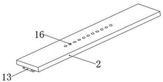
FIG. 3 is a schematic view of a supporting table according to the present invention.
In the figure: 1. a column; 2. a support table; 3. a support box; 4. a support pillar; 5. an electric cylinder; 6. a movable frame; 7. a guide post; 8. a universal wheel; 9. a reinforcement tube; 10. adjusting a rod; 11. bracing; 12. a support plate; 13. a slide rail; 14. pipe sleeve; 15. positioning the bolt; 16. positioning holes; 17. a rubber pad; 18. a handle.
Detailed Description
The technical solutions in the embodiments of the present invention will be clearly and completely described below with reference to the drawings in the embodiments of the present invention, and it is obvious that the described embodiments are only a part of the embodiments of the present invention, and not all of the embodiments. All other embodiments, which can be derived by a person skilled in the art from the embodiments given herein without making any creative effort, shall fall within the protection scope of the present invention.
Example (b): referring to fig. 1-3, a novel building supporting beam structure comprises two upright columns 1 distributed along the vertical direction, wherein the bottom ends of the upright columns 1 are connected with supporting boxes 3 through bolts, the supporting boxes 3 are hollow structures, supporting columns 4 are vertically arranged at four corners of the bottom surface of each supporting box 3, the support column 4 and the support box 3 are welded and fixed, the top surface inside the support box 3 is provided with an electric cylinder 5, a piston rod of the electric cylinder 5 is vertically downward and is connected with a movable frame 6, the movable frame 6 is cross-shaped, the bottom surfaces of the four end parts of the movable frame 6 are respectively and vertically provided with a guide column 7, the guide columns 7 are welded and fixed with the movable frame 6, the bottom parts of the guide columns 7 penetrate through the bottom surface of the support box 3 and are provided with universal wheels 8, namely, the height of the universal wheel 8 can be adjusted, so that the upright post 1 can slide through the universal wheel 8 and can also be fixed on the ground through the supporting column 4; two 1 looks one sides in opposite directions of stand all are equipped with the reinforced pipe 9 that distributes along the horizontal direction, bolted connection is fixed between reinforced pipe 9 and the stand 1, be equipped with between two reinforced pipes 9 and adjust pole 10, the both ends of adjusting pole 10 insert respectively in two reinforced pipes 9, and the internal thread has been seted up to the inner wall of reinforced pipe 9, adjust both ends and seted up the external screw thread that revolves to opposite respectively about pole 10, reinforced pipe 9 and adjust screw-thread fit between the pole 10, the fixed cover in middle section of adjusting pole 10 is equipped with handle 18, handle 18 is used for making things convenient for operating personnel to rotate and adjusts pole 10, therefore, can indirectly control two stands 1 through twist grip 18 and be close to each other or keep away from.
Inclined struts 11 are obliquely arranged on one opposite surfaces of the two stand columns 1 and above the reinforcing pipes 9, the inclined struts 11 are welded and fixed with the stand columns 1, supporting plates 12 are horizontally arranged at the top ends of the inclined struts 11, the top surfaces of the supporting plates 12 are flush with the top surfaces of the stand columns 1, supporting tables 2 distributed in the horizontal direction are arranged above the two stand columns 1, sliding rails 13 distributed in the length direction of the supporting tables 2 are arranged on the left side and the right side of the bottom surfaces of the supporting tables 2, the sliding rails 13 and the supporting tables 2 are integrally formed, elastic rubber pads 17 are attached to the top surfaces of the supporting tables 2, the rubber pads 17 are made of rubber materials, and the sliding rails 13 are in sliding fit with the tops of the stand columns 1; the bottom surface of backup pad 12 is equipped with pipe box 14, the internal thread has been seted up to the inner wall of pipe box 14, and pipe box 14 threaded connection has positioning bolt 15, positioning bolt 15's bottom is located the below of pipe box 14, positioning bolt 15's top runs through backup pad 12 and extends to the top of backup pad 12, prop up the length direction that the bench 2 was gone up and evenly run through along the bench 2 and set up with positioning bolt 15 assorted locating hole 16, when positioning bolt 15 runs through to the inside back of pipe box 14, the relative position of bench 2 and stand 1 is fixed.
In summary, in the specific use process of the present invention, the distance between the two columns can be adjusted by using the reinforced pipe 9 and the adjusting rod 10, and then the supporting platform 2 is fixed above the column 1 by using the positioning bolt 15; when the crossbeam is installed, the crossbeam is accepted to usable brace table 2, avoids the crossbeam to rock about because of hanging on lifting device, in addition, owing to be provided with universal wheel 8 on the supporting box 3, consequently, the position of stand 1 also can be through workman manual adjustment, and then aligns the tip of crossbeam and the connecting piece on the building, has further made things convenient for operating personnel to install the crossbeam.
It should be noted that, in this document, the terms "comprises," "comprising," or any other variation thereof, are intended to cover a non-exclusive inclusion, such that a process, method, article, or apparatus that comprises a list of elements does not include only those elements but may include other elements not expressly listed or inherent to such process, method, article, or apparatus. Without further limitation, an element defined by the phrase "comprising an … …" does not exclude the presence of other identical elements in a process, method, article, or apparatus that comprises the element.
Although embodiments of the present invention have been shown and described, it will be appreciated by those skilled in the art that changes, modifications, substitutions and alterations can be made in these embodiments without departing from the principles and spirit of the utility model, the scope of which is defined in the appended claims and their equivalents.
Claims (5)
1. The utility model provides a novel building supporting beam structure, includes two stands (1) that distribute along vertical direction, its characterized in that: the bottom end of the upright post (1) is provided with a supporting box (3), the supporting box (3) is of a hollow structure, four corners of the bottom surface of the supporting box (3) are respectively and vertically provided with a supporting column (4), the top surface inside the supporting box (3) is provided with an electric cylinder (5), a piston rod of the electric cylinder (5) vertically faces downwards and is connected with a movable frame (6), the movable frame (6) is cross-shaped, the bottom surfaces of four end parts of the movable frame (6) are respectively and vertically provided with a guide column (7), and the bottom of each guide column (7) penetrates through the bottom surface of the supporting box (3) and is provided with a universal wheel (8); two stand (1) one side in opposite directions all is equipped with reinforced pipe (9) along the horizontal direction distribution, two be equipped with between reinforced pipe (9) and adjust pole (10), the both ends of adjusting pole (10) insert respectively in two reinforced pipe (9), and the inner wall of reinforced pipe (9) is seted up there is the internal thread, adjusts pole (10) about both ends seted up respectively to revolve to opposite external screw thread, reinforced pipe (9) and adjust screw-thread fit between pole (10).
2. A novel building support beam structure according to claim 1, wherein: two stand (1) one side in opposite directions just is located the top of reinforced pipe (9) and all inclines to be provided with bracing (11), the top level of bracing (11) is provided with backup pad (12), the top surface of backup pad (12) and the top surface parallel and level of stand (1).
3. A novel building support beam structure according to claim 2, wherein: two the top of stand (1) is equipped with brace table (2) along the horizontal direction distribution, the bottom surface left and right sides of brace table (2) all is equipped with along slide rail (13) that brace table (2) length direction distributes, and the top surface laminating of brace table (2) is equipped with has elastic cushion (17), the top sliding fit of slide rail (13) and stand (1).
4. A novel building support beam structure according to claim 3, wherein: the bottom surface of backup pad (12) is equipped with pipe box (14), pipe box (14) internal threaded connection has positioning bolt (15), the top of positioning bolt (15) runs through backup pad (12) and extends to the top of backup pad (12), on brace table (2) and along the length direction of brace table (2) evenly run through set up with positioning hole (16) of positioning bolt (15) assorted.
5. A novel building support beam structure according to claim 1, wherein: the middle section of the adjusting rod (10) is fixedly sleeved with a handle (18).
Priority Applications (1)
| Application Number | Priority Date | Filing Date | Title |
|---|---|---|---|
| CN202122386857.XU CN215978516U (en) | 2021-09-30 | 2021-09-30 | Novel building supporting beam structure |
Applications Claiming Priority (1)
| Application Number | Priority Date | Filing Date | Title |
|---|---|---|---|
| CN202122386857.XU CN215978516U (en) | 2021-09-30 | 2021-09-30 | Novel building supporting beam structure |
Publications (1)
| Publication Number | Publication Date |
|---|---|
| CN215978516U true CN215978516U (en) | 2022-03-08 |
Family
ID=80508679
Family Applications (1)
| Application Number | Title | Priority Date | Filing Date |
|---|---|---|---|
| CN202122386857.XU Active CN215978516U (en) | 2021-09-30 | 2021-09-30 | Novel building supporting beam structure |
Country Status (1)
| Country | Link |
|---|---|
| CN (1) | CN215978516U (en) |
-
2021
- 2021-09-30 CN CN202122386857.XU patent/CN215978516U/en active Active
Similar Documents
| Publication | Publication Date | Title |
|---|---|---|
| CN209760750U (en) | Movable lifting scaffold | |
| CN105178626B (en) | The pressure computational methods of light-duty multifunctional supporting arrangement | |
| CN217175586U (en) | Operating platform for slope construction | |
| CN215978516U (en) | Novel building supporting beam structure | |
| CN211775601U (en) | Scaffold for bridge construction | |
| CN213626572U (en) | Tool type external cantilever operation platform | |
| CN211473390U (en) | Concrete beam formwork | |
| CN213838527U (en) | Novel geological survey probing device | |
| CN212893618U (en) | Tower crane steel platform support structure with adjustable | |
| CN210888010U (en) | Construction handling frame | |
| CN211597633U (en) | Scaffold for building engineering that can install fast | |
| CN204354853U (en) | The auxiliary construction device that a kind of electrified railway is built | |
| CN210828241U (en) | Detachable building scaffold | |
| CN202206102U (en) | Unwinding rack used for construction site | |
| CN105484661A (en) | Movable inclined ladder | |
| CN112962942A (en) | Height-adjustable scaffold for interior decoration | |
| CN211556630U (en) | 110KV outdoor GIS equipment installation auxiliary tool | |
| CN220149061U (en) | Quick lifting support for adjustable sliding rail in bin | |
| CN219732716U (en) | Complete equipment for safety quality control of installation of full-bolt connection steel structure | |
| CN205168844U (en) | Building berth carries and supports pylon with hull | |
| CN220679857U (en) | Triangular column welding tool | |
| CN215154766U (en) | Fixed bolster is used in municipal pipeline construction | |
| CN220267160U (en) | Safety belt tying rack | |
| CN216471907U (en) | Assembled movable multidirectional adjusting hoisting platform | |
| CN213834248U (en) | Adjustable steel beam connecting plate mounting frame body |
Legal Events
| Date | Code | Title | Description |
|---|---|---|---|
| GR01 | Patent grant | ||
| GR01 | Patent grant |