CN215946689U - Power maintenance frame - Google Patents
Power maintenance frame Download PDFInfo
- Publication number
- CN215946689U CN215946689U CN202122635314.7U CN202122635314U CN215946689U CN 215946689 U CN215946689 U CN 215946689U CN 202122635314 U CN202122635314 U CN 202122635314U CN 215946689 U CN215946689 U CN 215946689U
- Authority
- CN
- China
- Prior art keywords
- main body
- base main
- rod
- torsion spring
- power maintenance
- Prior art date
- Legal status (The legal status is an assumption and is not a legal conclusion. Google has not performed a legal analysis and makes no representation as to the accuracy of the status listed.)
- Active
Links
Images


Abstract
The utility model discloses a power maintenance frame, which comprises a base main body and a hydraulic rod fixed above the middle of the base main body, wherein the base main body is provided with a plurality of grooves; the bottom end of the platform mechanism is connected with the top end of the telescopic frame, and the bottom end of the telescopic frame is connected with the upper surface of the base main body; further comprising: the two threaded rods are symmetrically arranged inside the base main body about the vertical central line of the base main body, and the bottom ends of the threaded rods are connected with the inner bearing of the base main body; the outer side of the lower end of the threaded rod is in threaded connection with an installation rod, and the bottom end of the installation rod penetrates through the bottom surface of the base main body and is connected with the fixed sucker. This power maintenance frame is provided with installation pole and fixed suction cup for fixed suction cup adsorbs fixedly with work area, can improve the steadiness that whole power maintenance frame placed from this, simultaneously through the setting of connecting rope and threaded rod, makes then the threaded rod drive threaded connection's installation pole decline, does not need to use the power supply and also does not need staff's manual regulation then.
Description
Technical Field
The utility model relates to the technical field of power maintenance frames, in particular to a power maintenance frame.
Background
The power maintenance frame can drive maintenance personal to rise to the certain height and assist the support body that carries out circuit maintenance, and current power maintenance frame kind is many, but still has certain problem when using, for example:
the patent name disclosed as CN205500711U is 'liftable power maintenance frame', the purpose of height adjustment of the maintenance frame is realized through the cooperation of a hydraulic jack and a lifting support, maintenance personnel operate the maintenance frame on a workbench, the automation degree is high, the maintenance device is safe and reliable, a platform for simultaneous operation can be provided for multiple people, the maintenance device is extended when in use during work, and the maintenance device is retracted when not in use and does not occupy too large space, but the whole maintenance frame is moved through a moving wheel at the bottom, even if the moving wheel is locked at the later stage, the whole maintenance frame can be moved easily when being placed, so that the stability of the whole maintenance frame is poor;
therefore, the power maintenance frame can well solve the problems.
SUMMERY OF THE UTILITY MODEL
The utility model aims to provide a power maintenance frame, which aims to solve the problems that the whole maintenance frame is easy to move when being placed and has poor placing stability even if the moving wheels are locked at a later stage after the whole maintenance frame moves through the moving wheels at the bottom in the market in the background technology.
In order to achieve the purpose, the utility model provides the following technical scheme: a power maintenance frame comprises a base main body and a hydraulic rod fixed above the middle of the base main body;
the two telescopic frames are respectively arranged on the front side and the rear side of the hydraulic rod, and the top end of the hydraulic rod is fixed with one side surface of the two telescopic frames;
the bottom end of the platform mechanism is connected with the top end of the telescopic frame, and the bottom end of the telescopic frame is connected with the upper surface of the base main body;
further comprising:
the two threaded rods are symmetrically arranged inside the base main body about the vertical central line of the base main body, and the bottom ends of the threaded rods are connected with the inner bearing of the base main body;
the outer side of the lower end of the threaded rod is in threaded connection with an installation rod, and the bottom end of the installation rod penetrates through the bottom surface of the base main body and is connected with the fixed sucker;
two shielding plates, it sets up respectively the left and right sides of platform mechanism, and the inside regulation and control axostylus axostyle that is fixed with that runs through of one end of shielding plate to the both ends of regulation and control axostylus axostyle all are connected with platform mechanism's inner bearing.
Preferably, a first torsion spring is nested outside the upper end of the threaded rod, the bottom end of the first torsion spring is fixedly connected with the upper surface of the base main body, the top end of the first torsion spring is connected with the threaded rod, and a first rope winding disc is connected to the outside key of the top end of the threaded rod.
Through the arrangement of the structure, the first rope winding disc can drive the threaded rod to rotate.
Preferably, a first torsion spring is arranged below the first rope winding disc, a connecting rope is wound and connected to the outer side of the first rope winding disc, and the top end of the connecting rope is connected with the output end of the hydraulic rod.
Through the arrangement of the structure, the connecting rope can drive the first rope winding disc to rotate.
Preferably, the installation rod and the fixed sucker form a lifting structure with the base body through a threaded rod, and the installation rod and the fixed sucker are arranged in a one-to-one correspondence manner.
Through the arrangement of the structure, the mounting rod drives the fixed sucker to descend together to perform later-stage adsorption work.
Preferably, the outer sides of the two ends of the regulating shaft rod are all provided with second torsion springs in an embedded mode, the outer sides of the two ends of the regulating shaft rod are all in key connection with second rope winding discs, and one side of each second torsion spring is provided with a second rope winding disc.
Through the arrangement of the structure, the second rope winding disc can drive the regulating shaft lever to rotate.
Preferably, one end of the second torsion spring is fixedly connected with the platform mechanism, the other end of the second torsion spring is fixedly connected with the regulating and controlling shaft lever, and the number of the second torsion springs and the number of the regulating and controlling shaft lever are set to be 2: 1.
Through the arrangement of the structure, the two torsion springs can conveniently store force.
Preferably, the outer side of the second rope winding disc is connected with a control rope in a winding mode, and the bottom end of the control rope is fixedly connected with the upper surface of the base main body.
Through the arrangement of the structure, the control rope can drive the second rope winding disc to rotate.
Compared with the prior art, the utility model has the beneficial effects that: this power maintenance frame can rotate the shielding plate and place, reduces the height of whole maintenance frame, can improve the steadiness that the maintenance frame was placed, and its specific content is as follows:
(1) the installation rod and the fixed sucker are arranged, the fixed sucker is driven to descend by the installation rod, so that the fixed sucker and a working area are fixedly adsorbed, the stability of the whole power maintenance frame can be improved, meanwhile, the threaded rod is driven to rotate by the connecting rope when the platform mechanism ascends by the arrangement of the connecting rope and the threaded rod, then the threaded rod drives the installation rod in threaded connection to descend, and further, the power source and the manual adjustment of workers are not needed, so that the power maintenance frame is convenient to use;
(2) install the shielding plate, the shielding plate can regulate and control the axostylus axostyle and rotate the below to platform mechanism as the centre of a circle, and the height of reducible whole maintenance frame from this is convenient for reduce the area occupied of whole maintenance frame, and the while is convenient for adjust the shielding plate automatically through control rope and second torsion spring's setting.
Drawings
FIG. 1 is a schematic main sectional view of the present invention;
FIG. 2 is a main sectional structural view of the mounting rod of the present invention;
FIG. 3 is a side sectional view of the connection between the shielding plate and the platform mechanism according to the present invention;
FIG. 4 is an enlarged view of the structure at A in FIG. 3 according to the present invention;
FIG. 5 is a schematic view of a descending structure of the platform mechanism of the present invention.
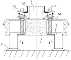
In the figure: 1. a base body; 2. a telescopic frame; 3. a hydraulic lever; 4. a platform mechanism; 5. a shielding plate; 6. a control cord; 7. a threaded rod; 7-1, a first torsion spring; 7-2, a first rope winding disc; 8. mounting a rod; 9. fixing the sucker; 10. connecting ropes; 11. regulating and controlling the shaft lever; 11-1, a second torsion spring; 11-2 and a second rope winding disc.
Detailed Description
The technical solutions in the embodiments of the present invention will be clearly and completely described below with reference to the drawings in the embodiments of the present invention, and it is obvious that the described embodiments are only a part of the embodiments of the present invention, and not all of the embodiments. All other embodiments, which can be derived by a person skilled in the art from the embodiments given herein without making any creative effort, shall fall within the protection scope of the present invention.
Referring to fig. 1-5, the present invention provides a technical solution: a power maintenance frame comprises a base main body 1, a hydraulic rod 3 fixed above the middle of the base main body 1, two telescopic frames 2 respectively arranged at the front side and the rear side of the hydraulic rod 3, and the top end of the hydraulic rod 3 is fixed with one side surface of the two telescopic frames 2, as shown in figure 5, the whole maintenance frame is moved into a working area, after the maintenance frame reaches the working area, a worker stands on the platform mechanism 4, then the hydraulic rod 3 is started, the output end of the hydraulic rod 3 drives the telescopic frame 2 to stretch, so that the telescopic frame 2 drives the platform mechanism 4 to ascend, the platform mechanism 4, the bottom end of the telescopic frame is connected with the top end of the telescopic frame 2, the bottom end of the telescopic frame 2 is connected with the upper surface of the base main body 1, when the platform mechanism 4 rises to a certain height position, the work of the hydraulic rod 3 is stopped, and then a worker can stand on the platform mechanism 4 to carry out maintenance work on the electric power;
the outer sides of two ends of the regulating shaft lever 11 are respectively provided with a second torsion spring 11-1 in an embedded mode, the outer sides of two ends of the regulating shaft lever 11 are respectively connected with a second rope winding disc 11-2 in a key mode, one side of the second torsion spring 11-1 is provided with a second rope winding disc 11-2, one end of the second torsion spring 11-1 is fixedly connected with the platform mechanism 4, the other end of the second torsion spring 11-1 is fixedly connected with the regulating shaft lever 11, the number of the second torsion springs 11-1 and the number of the regulating shaft lever 11 are 2:1, meanwhile, the regulating shaft lever 11 stores force on the second torsion spring 11-1 during rotation, so that the regulating shaft lever 11 is driven by the stored force of the second torsion spring 11-1 to reversely rotate and reset, then the regulating shaft lever 11 drives the shielding plate 5 to rotate, and the shielding plate 5 rotates above the platform mechanism 4, platform mechanism 4 is perpendicular setting with shielding plate 5, therefore shielding plate 5 alright shelter from and protected the staff on platform mechanism 4, the outside winding of second wire winding dish 11-2 is connected with control rope 6, and the bottom of control rope 6 and the last fixed surface of base main part 1 are connected, when platform mechanism 4 rose, base main part 1 was fixed the bottom of control rope 6, make the top of control rope 6 from this spurted, then made control rope 6 drive second wire winding dish 11-2 and regulation and control axostylus axostyle 11 rotate.
Further comprising: the outer side of the upper end of the threaded rod 7 is provided with a first torsion spring 7-1 in a nested mode, the bottom end of the first torsion spring 7-1 is fixedly connected with the upper surface of the base main body 1, the top end of the first torsion spring 7-1 is connected with the threaded rod 7, the threaded rod 7 stores force on the first torsion spring 7-1 during rotation so as to drive the threaded rod 7 to reversely rotate and reset in the later period through the stored force of the first torsion spring 7-1, wherein the outer side of the lower end of the threaded rod 7 is connected with an installation rod 8 in a threaded mode, the bottom end of the installation rod 8 penetrates through the bottom surface of the base main body 1 to be connected with a fixed sucker 9, the installation rod 8 and the fixed sucker 9 form a lifting structure with the base main body 1 through the threaded rod 7, the installation rods 8 and the fixed suckers 9 are arranged in a one-to-one correspondence mode, and then the installation rod 8 connected with the outer side of the lower end of the threaded rod 7 is driven to move downwards during rotation, make installation pole 8 drive fixed suction cup 9 downstream then, consequently make fixed suction cup 9 adsorb fixedly with work area, improve the steadiness that whole maintenance frame placed.
The outer side of the top end of the threaded rod 7 is connected with a first rope winding disc 7-2 through a key, a first torsion spring 7-1 is arranged below the first rope winding disc 7-2, the outer side of the first rope winding disc 7-2 is connected with a connecting rope 10 in a winding way, and the top end of the connecting rope 10 is connected with the output end of the hydraulic rod 3, as shown in the attached fig. 1-2, when the output end of the hydraulic rod 3 rises, the connecting rope 10 fixed at the left and right ends is pulled, when the connecting rope 10 with a certain length is pulled to be in a vertical state, the connecting rope 10 wound on the first rope winding disc 7-2 is continuously pulled, therefore, the connecting rope 10 drives the first rope winding disc 7-2 and the threaded rods 7 to rotate, the two threaded rods 7 are symmetrically arranged in the base main body 1 about the vertical central line of the base main body 1, and the bottom ends of the threaded rods 7 are connected with the inner bearing of the base main body 1;
two shielding plates 5, it sets up respectively in the left and right sides of platform mechanism 4, and the inside regulation and control axostylus axostyle 11 that is fixed with that runs through of one end of shielding plate 5 to the both ends of regulation and control axostylus axostyle 11 all are connected with the inner bearing of platform mechanism 4.
After the later stage is used, as shown above, on the same principle, when platform mechanism 4 descends, hold power through second torsion spring 11-1 and drive regulation and control axostylus axostyle 11 antiport, make regulation and control axostylus axostyle 11 drive shielding plate 5 rotatory, make shielding plate 5 rotatory to platform mechanism 4's below, as shown in figure 5, avoid shielding plate 5 to occupy great space, on the same principle, hold power through first torsion spring 7-1 and drive threaded rod 7 antiport, make fixed suction cup 9 and work area separate, then be convenient for later stage base main part 1 to remove.
The working principle is as follows: when the power maintenance frame is used, the output end of the hydraulic rod 3 drives the telescopic frame 2 to stretch;
when the platform mechanism 4 rises, the control rope 6 drives the second rope winding disc 11-2 and the regulating shaft lever 11 to rotate, and then the regulating shaft lever 11 drives the baffle plate 5 to rotate, so that the baffle plate 5 rotates above the platform mechanism 4;
when the output end of the hydraulic rod 3 rises, the connecting rope 10 fixed at the left end and the right end is pulled, so that the connecting rope 10 drives the first rope winding disc 7-2 and the threaded rod 7 to rotate, then the threaded rod 7 drives the mounting rod 8 in threaded connection with the outer side of the lower end to move downwards when rotating, and then the fixed sucker 9 is fixedly adsorbed to a working area;
after the end of the later use, as shown above, and in the same way, when the platform mechanism 4 descends, the shielding plate 5 is rotated to the lower side of the platform mechanism 4, so that the fixed suction cup 9 is separated from the working area, and what is not described in detail in this specification belongs to the prior art known to those skilled in the art.
Although the present invention has been described in detail with reference to the foregoing embodiments, it will be apparent to those skilled in the art that various changes in the embodiments and/or modifications of the utility model can be made, and equivalents and modifications of some features of the utility model can be made without departing from the spirit and scope of the utility model.
Claims (7)
1. A power maintenance frame comprises a base main body (1) and a hydraulic rod (3) fixed above the middle of the base main body (1);
the two telescopic frames (2) are respectively arranged on the front side and the rear side of the hydraulic rod (3), and the top end of the hydraulic rod (3) is fixed with one side surface of the two telescopic frames (2);
the bottom end of the platform mechanism (4) is connected with the top end of the telescopic frame (2), and the bottom end of the telescopic frame (2) is connected with the upper surface of the base main body (1);
it is characterized by also comprising:
the two threaded rods (7) are symmetrically arranged inside the base main body (1) about the vertical central line of the base main body (1), and the bottom ends of the threaded rods (7) are connected with an internal bearing of the base main body (1);
the outer side of the lower end of the threaded rod (7) is in threaded connection with an installation rod (8), and the bottom end of the installation rod (8) penetrates through the bottom surface of the base main body (1) and is connected with a fixed sucker (9);
two shielding plates (5) are respectively arranged on the left side and the right side of the platform mechanism (4), a regulating shaft lever (11) penetrates through and is fixed in one end of each shielding plate (5), and the two ends of each regulating shaft lever (11) are connected with an inner bearing of the platform mechanism (4).
2. A power maintenance stand according to claim 1, wherein: the outer side of the upper end of the threaded rod (7) is provided with a first torsion spring (7-1) in a nested mode, the bottom end of the first torsion spring (7-1) is fixedly connected with the upper surface of the base main body (1), the top end of the first torsion spring (7-1) is connected with the threaded rod (7), and the outer side of the top end of the threaded rod (7) is connected with a first rope winding disc (7-2) in a key mode.
3. A power maintenance rack according to claim 2, wherein: a first torsion spring (7-1) is arranged below the first rope winding disc (7-2), a connecting rope (10) is wound and connected to the outer side of the first rope winding disc (7-2), and the top end of the connecting rope (10) is connected with the output end of the hydraulic rod (3).
4. A power maintenance stand according to claim 1, wherein: the installation rod (8) and the fixed sucker (9) form a lifting structure with the base body (1) through the threaded rod (7), and the installation rod (8) and the fixed sucker (9) are arranged in a one-to-one correspondence mode.
5. A power maintenance stand according to claim 1, wherein: second torsion springs (11-1) are respectively arranged on the outer sides of the two ends of the regulating shaft lever (11) in a nested mode, second rope winding discs (11-2) are respectively connected to the outer sides of the two ends of the regulating shaft lever (11) in a key mode, and the second rope winding discs (11-2) are arranged on one side of each second torsion spring (11-1).
6. A power maintenance stand according to claim 5, wherein: one end of the second torsion spring (11-1) is fixedly connected with the platform mechanism (4), the other end of the second torsion spring (11-1) is fixedly connected with the regulating and controlling shaft lever (11), and the number of the second torsion springs (11-1) and the number of the regulating and controlling shaft levers (11) are arranged in a ratio of 2: 1.
7. A power maintenance stand according to claim 5, wherein: the outer side of the second rope winding disc (11-2) is connected with a control rope (6) in a winding mode, and the bottom end of the control rope (6) is fixedly connected with the upper surface of the base main body (1).
Priority Applications (1)
| Application Number | Priority Date | Filing Date | Title |
|---|---|---|---|
| CN202122635314.7U CN215946689U (en) | 2021-11-01 | 2021-11-01 | Power maintenance frame |
Applications Claiming Priority (1)
| Application Number | Priority Date | Filing Date | Title |
|---|---|---|---|
| CN202122635314.7U CN215946689U (en) | 2021-11-01 | 2021-11-01 | Power maintenance frame |
Publications (1)
| Publication Number | Publication Date |
|---|---|
| CN215946689U true CN215946689U (en) | 2022-03-04 |
Family
ID=80411497
Family Applications (1)
| Application Number | Title | Priority Date | Filing Date |
|---|---|---|---|
| CN202122635314.7U Active CN215946689U (en) | 2021-11-01 | 2021-11-01 | Power maintenance frame |
Country Status (1)
| Country | Link |
|---|---|
| CN (1) | CN215946689U (en) |
-
2021
- 2021-11-01 CN CN202122635314.7U patent/CN215946689U/en active Active
Similar Documents
| Publication | Publication Date | Title |
|---|---|---|
| CN209942188U (en) | Construction lift protection platform for building | |
| CN102008377A (en) | Stretcher with height-adjustable supporting legs | |
| CN108709058B (en) | Lifting type movable support for data acquisition | |
| CN108584825A (en) | A kind of electric power overhaul platform that can stablize lifting | |
| CN215946689U (en) | Power maintenance frame | |
| CN213696291U (en) | Office chair with height-adjustable seat | |
| CN208716788U (en) | A kind of electric power overhaul platform that can stablize lifting | |
| CN206091435U (en) | Do not occupy platform lifting parking device on road surface | |
| CN209276075U (en) | A kind of portable multifunctional elevator tooling | |
| CN206835739U (en) | A kind of garden landscape flower stand | |
| CN205676111U (en) | A kind of safe and reliable crane | |
| CN212802418U (en) | Over-and-under type operation device for construction | |
| CN212210916U (en) | Angle-adjustable solar power generation device | |
| CN210885009U (en) | Equipment hoisting alignment device for wind power generation | |
| CN220434261U (en) | Building construction platform of unloading | |
| CN214031614U (en) | Conveniently adjust aluminum alloy lift of transportation | |
| CN217296995U (en) | Cigarette rack lifting device | |
| CN210407549U (en) | Vertical lifting table | |
| CN217230088U (en) | Column type lifting mechanism | |
| CN218052521U (en) | Transformer maintenance crane | |
| CN214782743U (en) | Lifting clothes hanger | |
| CN213428927U (en) | Single-motor electric lifting table | |
| CN220363533U (en) | A mobile device for elevator guide rail packing | |
| CN219877674U (en) | Electric lifting table | |
| CN220223364U (en) | Device for adjusting angle of electric hoist |
Legal Events
| Date | Code | Title | Description |
|---|---|---|---|
| GR01 | Patent grant | ||
| GR01 | Patent grant |