CN215935306U - Over-and-under type electrical control cabinet for fire engineering - Google Patents
Over-and-under type electrical control cabinet for fire engineering Download PDFInfo
- Publication number
- CN215935306U CN215935306U CN202122591942.XU CN202122591942U CN215935306U CN 215935306 U CN215935306 U CN 215935306U CN 202122591942 U CN202122591942 U CN 202122591942U CN 215935306 U CN215935306 U CN 215935306U
- Authority
- CN
- China
- Prior art keywords
- control cabinet
- electrical control
- rod
- fixedly connected
- rack
- Prior art date
- Legal status (The legal status is an assumption and is not a legal conclusion. Google has not performed a legal analysis and makes no representation as to the accuracy of the status listed.)
- Active
Links
Images

Landscapes
- Patch Boards (AREA)
Abstract
The utility model relates to the technical field of electrical control cabinets, in particular to a lifting type electrical control cabinet for fire engineering. The utility model has the advantages that: rotate the second lead screw, make the rack slide at the surface of second guide bar, meshing connection relation through gear and rack, make the gear drive the dwang rotate, make the carousel pass through the effect of connecting rod, it rotates to drive the switch board main part, when having guaranteed to maintain electrical control cabinet, not only can go up and down electrical control cabinet, the convenience is maintained the electrical component of electrical control lever lower part, also accessible rotates electrical control cabinet, adjust the maintenance direction, the work efficiency of maintenance work is improved, make the maintenance of electrical control cabinet more convenient.
Description
Technical Field
The utility model relates to the technical field of electrical control cabinets, in particular to a lifting type electrical control cabinet for fire engineering.
Background
The electrical control cabinet is formed by assembling switch equipment, measuring instruments, protective electrical appliances and auxiliary equipment in a closed or semi-closed metal cabinet or on a screen according to the electrical wiring requirements, and the arrangement of the electrical control cabinet meets the requirement of normal operation of an electric power system, is convenient to overhaul and does not endanger the safety of people and surrounding equipment.
Current electrical control cabinet for fire engineering is when using, and the lifting function that does not possess mostly leads to when maintaining electrical control cabinet, inconvenient electric elements to electrical control cabinet lower part maintains, influences maintenance work's work efficiency.
SUMMERY OF THE UTILITY MODEL
The utility model aims to overcome the defects in the prior art, provides a lifting type electrical control cabinet for fire engineering, and effectively overcomes the defects in the prior art.
The purpose of the utility model is realized by the following technical scheme: the utility model provides a fire engineering uses over-and-under type electrical control cabinet, includes the framework, the top fixedly connected with motor of framework inner wall, one side of motor is provided with first lead screw, there is the sleeve pipe surface of first lead screw through threaded connection, sheathed tube one side fixedly connected with lifter plate, the first guide bar of one side fixedly connected with of lifter plate, one side fixedly connected with limiting plate of first guide bar, one side of lifter plate is rotated through the bearing and is connected with the dwang, one side fixedly connected with carousel of lifter plate is kept away from to the dwang, one side fixedly connected with connecting rod of dwang is kept away from to the carousel, one side fixedly connected with switch board main part of carousel is kept away from to the connecting rod.
Optionally, the outer fixed surface of dwang is connected with the gear, one side meshing of gear is connected with the rack, there is the second lead screw inside of rack through threaded connection, one side of second lead screw is connected with the connecting plate through the bearing rotation, one side fixed connection lifter plate of connecting plate, the inside sliding connection of rack has the second guide bar, one side and the connecting plate fixed connection of second guide bar.
Optionally, a vent is formed in one side of the frame body, and the thread pitch of the threads arranged on the outer surface of the first screw rod is matched with the thread pitch of the threads arranged on the inner wall of the sleeve.
Optionally, the diameter of the first guide rod is smaller than that of the limiting plate, and the diameter of the first guide rod is matched with that of the through hole formed in one side of the frame body.
Optionally, the axle center of dwang and the axle center coincidence of carousel, the quantity of connecting rod is four, four the connecting rod circumference array is in one side of carousel.
Optionally, the axis of the gear coincides with the axis of the rotating rod, and the tooth shape of the gear is matched with the tooth space of the rack.
Optionally, the second screw rod penetrates through the connecting plate, a contact surface between the second screw rod and the inner wall of the connecting plate is a smooth surface, and the diameter of the second guide rod is equal to that of the second screw rod.
The utility model has the following advantages:
the lifting type electrical control cabinet for the fire engineering comprises a frame body, a motor, a first lead screw, a sleeve, a lifting plate, a first guide rod, a limiting plate, a rotating rod, a rotating disk, a connecting rod, a control cabinet main body, a gear, a rack, a second lead screw, a connecting plate and a second guide rod which are arranged in a matched manner, wherein the motor drives the first lead screw to rotate, the first lead screw is connected with the frame body in a sliding manner through the first guide rod, the connecting length of the first lead screw and the sleeve is adjusted, the lifting plate is further lifted, the rotating rod drives the rotating disk to lift, the connecting rod drives the control cabinet main body to lift, the rack slides on the outer surface of the second guide rod by rotating the second lead screw, the gear drives the rotating rod to rotate through the meshed connection relationship of the gear and the rack, the rotating disk drives the control cabinet main body to rotate through the effect of the connecting rod, and the maintenance of the electrical control cabinet is ensured, not only can go up and down the electrical control cabinet, conveniently maintain the electrical element of electrical control pole lower part, also can adjust the maintenance direction through rotating the electrical control cabinet, improve maintenance work's work efficiency for the maintenance of electrical control cabinet is more convenient.
Drawings
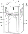
FIG. 1 is a schematic view of a first perspective structure of the present invention;
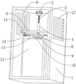
FIG. 2 is a schematic view of a second perspective structure of the present invention;
fig. 3 is a schematic cross-sectional structure of the present invention.
In the figure: 1-frame body, 2-motor, 3-first screw rod, 4-sleeve, 5-lifting plate, 6-first guide rod, 7-limiting plate, 8-rotating rod, 9-rotating disk, 10-connecting rod, 11-control cabinet body, 12-gear, 13-rack, 14-second screw rod, 15-connecting plate, 16-second guide rod and 17-ventilation opening.
Detailed Description
The utility model will be further described with reference to the accompanying drawings, but the scope of the utility model is not limited to the following.
As shown in fig. 1 to 3, a lifting electrical control cabinet for fire engineering comprises a frame body 1, a motor 2 is fixedly connected to the top of the inner wall of the frame body 1, a first lead screw 3 is arranged on one side of the motor 2, a sleeve 4 is connected to the outer surface of the first lead screw 3 through a thread, a lifting plate 5 is fixedly connected to one side of the sleeve 4, a first guide rod 6 is fixedly connected to one side of the lifting plate 5, a limit plate 7 is fixedly connected to one side of the first guide rod 6, a rotating rod 8 is rotatably connected to one side of the lifting plate 5 through a bearing, a rotating disc 9 is fixedly connected to one side of the rotating rod 8 far away from the lifting plate 5, a connecting rod 10 is fixedly connected to one side of the rotating disc 9 far away from the rotating rod 8, a control cabinet body 11 is fixedly connected to one side of the connecting rod 10 far away from the rotating disc 9, the motor 2 drives the first lead screw 3 to rotate, and is connected with the cabinet body 1 through the first guide rod 6 in a sliding manner, adjust the length of being connected of first lead screw 3 and sleeve pipe 4 for lifter plate 5 carries out elevating movement, makes dwang 8 drive carousel 9 carry out elevating movement, makes connecting rod 10 drive switch board main part 11 and goes up and down, height-adjusting.
As an optional technical scheme of the utility model: outer fixed surface of dwang 8 is connected with gear 12, one side meshing of gear 12 is connected with rack 13, there is second lead screw 14 inside of rack 13 through threaded connection, one side of second lead screw 14 is connected with connecting plate 15 through the bearing rotation, one side fixed connection lifter plate 5 of connecting plate 15, the inside sliding connection of rack 13 has second guide bar 16, one side and connecting plate 15 fixed connection of second guide bar 16, control second lead screw 14 rotates, make rack 13 slide at the surface of second guide bar 16, meshing connection relation through gear 12 and rack 13, make gear 12 drive dwang 8 rotate, make carousel 9 pass through the effect of connecting rod 10, it rotates to drive switch board main part 11.
As an optional technical scheme of the utility model: vent 17 has been seted up to one side of framework 1, and the pitch of the screw thread that the surface of first lead screw 3 set up and the pitch looks adaptation of the screw thread that the inner wall of sleeve pipe 4 set up adjust its and sleeve pipe 4's length of being connected through rotating first lead screw 3, and then make lifter plate 5 carry out elevating movement.
As an optional technical scheme of the utility model: the diameter of first guide bar 6 is less than the diameter of limiting plate 7, and the diameter looks adaptation of the through-hole that the diameter of first guide bar 6 and framework 1 one side were seted up is through the effect of first guide bar 6 for the elevating movement of lifter plate 5 is more smooth and easy, stable.
As an optional technical scheme of the utility model: the axle center of dwang 8 and the axle center coincidence of carousel 9, the quantity of connecting rod 10 is four, and four connecting rod 10 circumference arrays drive carousel 9 through dwang 8 and rotate in one side of carousel 9 for connecting rod 10 drives switch board main part 11 and rotates.
As an optional technical scheme of the utility model: the axis of the gear 12 coincides with the axis of the rotating rod 8, the tooth shape of the gear 12 is matched with the tooth space of the rack 13, and the gear 12 drives the rotating rod 8 to rotate when the rack 13 moves through the meshing connection relationship between the gear 12 and the rack 13.
As an optional technical scheme of the utility model: the second lead screw 14 runs through the connecting plate 15, the contact surface of the second lead screw 14 and the inner wall of the connecting plate 15 is a smooth surface, the diameter of the second guide rod 16 is equal to that of the second lead screw 14, and the position of the rack 13 is limited by the second guide rod 16, so that the rack 13 can move more smoothly and stably.
The working process of the utility model is as follows: when the user uses
1. The motor 2 drives the first screw rod 3 to rotate, and the first screw rod 3 is connected with the cabinet body 1 in a sliding manner through the first guide rod 6, so that the connection length of the first screw rod 3 and the sleeve 4 is adjusted, and the lifting plate 5 is further lifted;
2. the rotating rod 8 drives the rotating disc 9 to perform lifting movement, and drives the control cabinet main body 11 to lift and adjust the height under the action of the connecting rod 10;
3. rotating the second lead screw 14 so that the rack 13 slides on the outer surface of the second guide bar 16;
4. through the meshing connection relation of gear 12 and rack 13 for gear 12 drives dwang 8 and rotates, makes carousel 9 pass through the effect of connecting rod 10, drives switch board main part 11 and rotates.
In summary, the following steps: the lifting type electrical control cabinet for the fire engineering is characterized in that through the matching arrangement of a frame body 1, a motor 2, a first lead screw 3, a sleeve 4, a lifting plate 5, a first guide rod 6, a limiting plate 7, a rotating rod 8, a rotary table 9, a connecting rod 10, a control cabinet main body 11, a gear 12, a rack 13, a second lead screw 14, a connecting plate 15 and a second guide rod 16, the motor 2 drives the first lead screw 3 to rotate, the connecting length of the first lead screw 3 and the sleeve 4 is adjusted through the sliding connection of the first guide rod 6 and the frame body 1, the lifting plate 5 is lifted, the rotating rod 8 drives the rotary table 9 to lift, the connecting rod 10 drives the control cabinet main body 11 to lift, the rack 13 slides on the outer surface of the second guide rod 16 through the rotation of the second lead screw 14, and the gear 12 drives the rotating rod 8 to rotate through the meshing connection relationship of the gear 12 and the rack 13, make carousel 9 through the effect of connecting rod 10, drive switch board main part 11 and rotate, guaranteed when maintaining electrical control cabinet, not only can go up and down electrical control cabinet, conveniently maintain the electrical component of electrical control pole lower part, also accessible rotate electrical control cabinet, adjust the maintenance direction, improve maintenance work's work efficiency for electrical control cabinet's maintenance is more convenient.
Although embodiments of the present invention have been shown and described, it will be appreciated by those skilled in the art that changes, modifications, substitutions and alterations can be made in these embodiments without departing from the principles and spirit of the utility model, the scope of which is defined in the appended claims and their equivalents.
Claims (7)
1. The utility model provides a fire engineering is with over-and-under type electrical control cabinet which characterized in that: comprises a frame body (1), a motor (2) is fixedly connected with the top of the inner wall of the frame body (1), a first screw rod (3) is arranged on one side of the motor (2), the outer surface of the first screw rod (3) is connected with a sleeve (4) through threads, one side of the sleeve (4) is fixedly connected with a lifting plate (5), one side of the lifting plate (5) is fixedly connected with a first guide rod (6), one side of the first guide rod (6) is fixedly connected with a limit plate (7), one side of the lifting plate (5) is rotatably connected with a rotating rod (8) through a bearing, a turntable (9) is fixedly connected on one side of the rotating rod (8) far away from the lifting plate (5), a connecting rod (10) is fixedly connected with one side of the turntable (9) far away from the rotating rod (8), one side of the connecting rod (10) far away from the turntable (9) is fixedly connected with a control cabinet main body (11).
2. The elevating electrical control cabinet for fire engineering of claim 1, wherein: the outer fixed surface of dwang (8) is connected with gear (12), one side meshing of gear (12) is connected with rack (13), there is second lead screw (14) inside of rack (13) through threaded connection, one side of second lead screw (14) is rotated through the bearing and is connected with connecting plate (15), one side fixed connection lifter plate (5) of connecting plate (15), the inside sliding connection of rack (13) has second guide bar (16), one side and connecting plate (15) fixed connection of second guide bar (16).
3. The elevating electrical control cabinet for fire engineering of claim 1, wherein: vent (17) have been seted up to one side of framework (1), the pitch of the screw thread that first lead screw (3) surface set up and the screw thread pitch looks adaptation of the screw thread that sleeve pipe (4) inner wall set up.
4. The elevating electrical control cabinet for fire engineering of claim 1, wherein: the diameter of the first guide rod (6) is smaller than that of the limiting plate (7), and the diameter of the first guide rod (6) is matched with that of the through hole formed in one side of the frame body (1).
5. The elevating electrical control cabinet for fire engineering of claim 1, wherein: the axle center of dwang (8) and the axle center coincidence of carousel (9), the quantity of connecting rod (10) is four, four connecting rod (10) circumference array is in one side of carousel (9).
6. The elevating electrical control cabinet for fire engineering of claim 2, wherein: the axle center of gear (12) and the axle center coincidence of dwang (8), the tooth form of gear (12) and the tooth's socket looks adaptation of rack (13).
7. The elevating electrical control cabinet for fire engineering of claim 2, wherein: the second screw rod (14) penetrates through the connecting plate (15), the contact surface of the second screw rod (14) and the inner wall of the connecting plate (15) is a smooth surface, and the diameter of the second guide rod (16) is equal to that of the second screw rod (14).
Priority Applications (1)
| Application Number | Priority Date | Filing Date | Title |
|---|---|---|---|
| CN202122591942.XU CN215935306U (en) | 2021-10-27 | 2021-10-27 | Over-and-under type electrical control cabinet for fire engineering |
Applications Claiming Priority (1)
| Application Number | Priority Date | Filing Date | Title |
|---|---|---|---|
| CN202122591942.XU CN215935306U (en) | 2021-10-27 | 2021-10-27 | Over-and-under type electrical control cabinet for fire engineering |
Publications (1)
| Publication Number | Publication Date |
|---|---|
| CN215935306U true CN215935306U (en) | 2022-03-01 |
Family
ID=80403552
Family Applications (1)
| Application Number | Title | Priority Date | Filing Date |
|---|---|---|---|
| CN202122591942.XU Active CN215935306U (en) | 2021-10-27 | 2021-10-27 | Over-and-under type electrical control cabinet for fire engineering |
Country Status (1)
| Country | Link |
|---|---|
| CN (1) | CN215935306U (en) |
Cited By (2)
| Publication number | Priority date | Publication date | Assignee | Title |
|---|---|---|---|---|
| CN115275798A (en) * | 2022-08-29 | 2022-11-01 | 江苏鸿康电器有限公司 | Switching device and power distribution equipment |
| CN116634706A (en) * | 2023-04-21 | 2023-08-22 | 苏州当至创网络科技有限公司 | Secure communication device for blockchain and communication system thereof |
-
2021
- 2021-10-27 CN CN202122591942.XU patent/CN215935306U/en active Active
Cited By (4)
| Publication number | Priority date | Publication date | Assignee | Title |
|---|---|---|---|---|
| CN115275798A (en) * | 2022-08-29 | 2022-11-01 | 江苏鸿康电器有限公司 | Switching device and power distribution equipment |
| CN115275798B (en) * | 2022-08-29 | 2023-07-25 | 江苏鸿康电器有限公司 | Switching device and power distribution equipment |
| CN116634706A (en) * | 2023-04-21 | 2023-08-22 | 苏州当至创网络科技有限公司 | Secure communication device for blockchain and communication system thereof |
| CN116634706B (en) * | 2023-04-21 | 2024-02-09 | 珠海市皓创信息技术有限公司 | Secure communication device for blockchain and communication system thereof |
Similar Documents
| Publication | Publication Date | Title |
|---|---|---|
| CN215935306U (en) | Over-and-under type electrical control cabinet for fire engineering | |
| CN108847598A (en) | A kind of distribution box with multi-faceted wind-blowing heat-dissipating function | |
| CN210939175U (en) | Multifunctional tool table for building electrical design | |
| CN112038927A (en) | Adjustable distribution control cabinet | |
| CN208394728U (en) | A kind of interior construction movable lifting device | |
| CN109998292A (en) | A kind of intelligence automatic lifting cabinet | |
| CN220348360U (en) | Positioning mechanism for mounting combined electrical appliance | |
| CN209350133U (en) | A kind of assembling diesel generator fixing tool | |
| CN217010220U (en) | Bridge cable device for machine room | |
| CN217721772U (en) | PLC constant voltage variable frequency control cabinet | |
| CN215011211U (en) | Computer network rack is with installation fixing device | |
| CN215835254U (en) | Linear motor and lifting device using same | |
| CN211554783U (en) | Industrial operating rod structure with multiple gears | |
| CN215813079U (en) | Mechanical electrical equipment detection device | |
| CN216201688U (en) | Laser adjusting mechanism | |
| CN218698504U (en) | Maintenance strutting arrangement convenient to upset electromechanical device | |
| CN219841349U (en) | Visual equipment operation panel | |
| CN217195178U (en) | Multifunctional tool table based on building electrical design | |
| CN221784007U (en) | Rotor core positioning device | |
| CN214100268U (en) | Electricity dish switch board with adjustable base | |
| CN217486031U (en) | Auxiliary device is used in debugging of electric power secondary equipment | |
| CN218407880U (en) | Lifting fan | |
| CN221508795U (en) | Electrical cabinet convenient to overhaul | |
| CN215171955U (en) | Multistage stop device in finite space | |
| CN221150688U (en) | Multi-mode combined integrated switch cabinet |
Legal Events
| Date | Code | Title | Description |
|---|---|---|---|
| GR01 | Patent grant | ||
| GR01 | Patent grant | ||
| TR01 | Transfer of patent right | ||
| TR01 | Transfer of patent right |
Effective date of registration: 20220830 Address after: 430000, No. 1, Taichung Avenue, Gaoqiao Industrial Park, Wujiashan Taiwan investment zone, Wuhan City, Hubei Province Patentee after: Wuhan Xinweida Installation Engineering Co.,Ltd. Address before: Room 1703, 262 Zhongshan Avenue middle, Tianhe District, Guangzhou, Guangdong 510000 Patentee before: Lai Yuhui |