CN215919808U - Engine support machining clamp capable of quickly clamping - Google Patents
Engine support machining clamp capable of quickly clamping Download PDFInfo
- Publication number
- CN215919808U CN215919808U CN202023319323.7U CN202023319323U CN215919808U CN 215919808 U CN215919808 U CN 215919808U CN 202023319323 U CN202023319323 U CN 202023319323U CN 215919808 U CN215919808 U CN 215919808U
- Authority
- CN
- China
- Prior art keywords
- clamping
- pressing
- clamp
- positioning
- bottom plate
- Prior art date
- Legal status (The legal status is an assumption and is not a legal conclusion. Google has not performed a legal analysis and makes no representation as to the accuracy of the status listed.)
- Active
Links
Images


Landscapes
- Jigs For Machine Tools (AREA)
Abstract
The utility model provides an engine bracket machining clamp capable of quickly clamping, which comprises: a clamp base plate; the fixture comprises a fixture base plate, at least one group of positioning components and a positioning component, wherein the fixture base plate comprises a first positioning column, a second positioning column, a third positioning column, a fourth positioning column, a third positioning column, a lateral support bar and a lateral support bar are arranged on the upper surface of the fixture base plate, a first limiting support bar is convexly provided with a lateral support, a lateral support bar, a first limiting support bar is arranged on the upper surface of the clamp base plate, a first limiting support bar, a clamp base plate, a first limiting support bar is arranged on the clamp base plate, a first limiting support bar is arranged on the clamp base plate, a first limiting support bar is arranged on the upper surface, and a first limiting support bar is arranged on the clamp base plate, a first limiting support bar; the clamping assembly comprises a clamping oil cylinder, a clamping piston rod is rotatably connected with a clamping connecting rod, and the clamping connecting rod is connected with a clamping pressure head; and the at least one group of pressing assemblies comprises pressing oil cylinders, pressing piston rods are connected with pressing connecting rods, and the pressing connecting rods are connected with pressing pressure heads. The fixture has the advantages that the fixture carries out centralized processing on the processes on the basis of ensuring the processing quality, the two processes are processed and are centralized into one process, and the fixture is arranged in space to process two finished products, so that the quality risk caused by the processing in different processes is reduced, the processing equipment resources are saved, the production cost is reduced, and the production benefit is improved.
Description
Technical Field
The utility model belongs to the technical field of clamp research and development, and particularly relates to an engine support machining clamp capable of quickly clamping.
Background
The existing clamp for processing the engine bracket has the main defects that:
1. the working procedures are added due to the sub-working procedure processing, so that the production efficiency is reduced, and the labor intensity of workers is increased;
2. because the product demand is high, the original clamp can only produce one finished product by one-time clamping, and the machine tool capacity is insufficient, so that the clamps and equipment are required to be added to meet the supply demand of the product, thereby occupying the production equipment resources, being not beneficial to the product production when the capacity is insufficient, and also increasing the clamp cost;
3. the two-step processing needs to design and control the process positioning size, the quality control cost is increased, and the product size debugging difficulty is increased.
SUMMERY OF THE UTILITY MODEL
In order to solve the existing problems, the utility model aims to provide an engine support machining clamp capable of quickly clamping, which is used for carrying out centralized processing on the working procedures on the basis of ensuring the machining quality, centralizing the two-procedure machining into one-procedure machining, and realizing that one clamp machines two finished products through the spatial arrangement of the clamp, so that the quality risk caused by the sub-procedure machining is reduced, the resources of machining equipment are saved, the production cost is reduced, and the production benefit is improved.
In order to achieve the purpose, the technical scheme of the utility model is as follows:
the utility model provides a but quick clamping's engine support adds clamping apparatus, includes: the clamp comprises a clamp bottom plate, a clamping device and a clamping device, wherein the clamp bottom plate is horizontally arranged, at least one clamping station is arranged on the clamp bottom plate, and an oil path inlet hole and an oil path outlet hole are formed in the edge of the upper surface of the clamp bottom plate at intervals; at least one group of positioning components, one clamping station is provided with a group of positioning components, the positioning components comprise first to third positioning columns which are arranged on the upper surface of the clamp bottom plate at intervals in a triangular mode, the first to third positioning columns correspond to three corners of an engine support, a lateral supporting block is vertically arranged on the upper surface of the clamp bottom plate between the first positioning column and the second positioning column, one surface of the lateral supporting block, facing a workpiece to be clamped, is convexly provided with a lateral supporting rod, a first limit supporting block is arranged on the upper surface of the clamp bottom plate corresponding to the outer side of the second positioning column, a first limit supporting rod is convexly arranged at one end of the first limit supporting block, which faces the second positioning column, a second limiting supporting block is arranged on the upper surface of the clamp bottom plate corresponding to the outer side of the third positioning column, and a second limiting supporting rod is convexly arranged at one end, facing the third positioning column, of the second limiting supporting block; the clamping assembly comprises a clamping oil cylinder which is vertically arranged on the upper surface of a clamp bottom plate between a second positioning column and a third positioning column, one end, far away from a clamping cylinder body, of a clamping piston rod of the clamping oil cylinder is rotatably connected with a clamping connecting rod, and one end, far away from the clamping piston rod, of the clamping connecting rod extends to the position above a workpiece to be clamped and is connected with a clamping pressure head; at least a set of compress tightly the subassembly, a clamping station sets up a set of subassembly that compresses tightly, compress tightly the subassembly including vertical setting in the compressing cylinder who is located the anchor clamps bottom plate upper surface between first reference column and the second reference column, compressing cylinder's compressing piston rod keeps away from compressing cylinder body one end swivelling joint and has a compression connecting rod, compressing connecting rod keeps away from compressing piston rod one end and extends to treating clamping work piece top and be connected with a pressure head that compresses tightly.
Furthermore, the number of the clamping stations is 2, and the 2 clamping stations are arranged at intervals along the length direction of the upper surface of the clamp bottom plate.
Furthermore, the upper surface of the clamp bottom plate corresponding to the lateral supporting block is provided with a mounting groove, and the lateral supporting block is arranged in the mounting groove.
Furthermore, a rotating seat is vertically arranged on the upper end surface of a clamping cylinder body of the clamping oil cylinder; a rotating shaft is convexly arranged on the side wall of at least one side of the rotating seat, and a rotating connecting plate is sleeved on the rotating shaft; a rotating fulcrum corresponding to the rotating shaft is convexly arranged in the middle of the length direction of the side wall of the clamping connecting rod, and one end of the rotating connecting plate, far away from the rotating shaft, is sleeved on the rotating fulcrum; the clamp link rotates about a pivot shaft.
Furthermore, the clamping oil cylinder is erected on the upper surface of the clamp bottom plate through a block; the clamping oil cylinder is a hydraulic oil cylinder.
Furthermore, a supporting seat is vertically arranged on the upper end surface of the pressing cylinder body of the pressing oil cylinder; a supporting pin is convexly arranged on the side wall of at least one side of the supporting seat, and a connecting plate is sleeved on the supporting pin; a rotating pin shaft corresponding to the supporting pin is convexly arranged in the middle of the side wall of the pressing connecting rod in the length direction, and one end, far away from the supporting pin, of the connecting plate is sleeved on the rotating pin shaft; the pressing connecting rod rotates by taking the rotating pin shaft as a shaft.
Furthermore, the upper surface of the clamp bottom plate corresponding to the pressing oil cylinder is provided with an installation through hole; the pressing cylinder body of the pressing oil cylinder is inserted into the mounting through hole, and the upper end face of the pressing cylinder body is positioned above the clamp bottom plate; the pressing oil cylinder is a hydraulic oil cylinder.
Furthermore, positioning grooves are formed in the upper surface of the clamp bottom plate corresponding to the first positioning columns, the second positioning columns and the third positioning columns; the first positioning column, the second positioning column, the third positioning column and the fourth positioning column are respectively inserted into a positioning groove; the first to third positioning columns are respectively tooth-shaped positioning bolts.
Further, the clamping pressure head is vertically connected to the bottom surface of one end, away from the clamping piston rod, of the clamping connecting rod; the clamping pressure head is a tooth-shaped positioning bolt.
Furthermore, one end of the compression connecting rod, which is far away from the compression piston rod, is bent upwards to form a bent part; the pressing pressure head is arranged on the bottom surface of one end of the bending part, which is far away from the pressing piston rod; the pressing pressure head is a tooth-shaped hard alloy pressure head.
The utility model has the beneficial effects that:
the product quality is improved: clamping assembly is with pressing from both sides tight hydro-cylinder and compressing tightly for the subassembly and compress tightly the hydro-cylinder, all adopt hydraulic cylinder drive, guarantee its clamping stability, and first ~ third reference column adopts the flute profile positioning bolt, improves anchor clamps stability to improve product quality.
The processing efficiency is improved: the original clamp only needs one clamp and one device to process one finished product, and the clamp only has two clamping stations on the clamp bottom plate, so that 2 finished products can be processed by one clamp and one device each time, the clamp and the processing device resources are reduced, and the production efficiency is greatly improved.
Reduce the clamping error: the clamping oil cylinder for the clamping assembly and the pressing oil cylinder for the pressing assembly are both driven by hydraulic oil cylinders, so that the phenomena of manual clamping errors and uneven stress are avoided; the clamping connecting rod and the pressing connecting rod are movable pressing plates, automatic adjustment is achieved in the pressing process, and uneven stress on two sides is avoided.
Increase anchor clamps rigidity, guarantee product processingquality: the design of the mounting through hole on the clamp bottom plate enables the clamping oil cylinder to be designed to be of a sinking type, so that the overall height of the clamp is convenient to reduce, the overall rigidity and strength of the clamp are improved, and the stability of the quality of a processed product is guaranteed.
Drawings
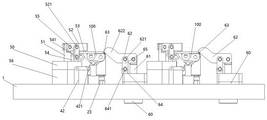
FIG. 1 is a schematic structural view of an engine bracket machining clamp capable of being clamped quickly according to an embodiment of the present invention;
FIG. 2 is a front view of FIG. 1;
FIG. 3 is a side view of FIG. 2;
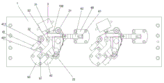
FIG. 4 is a top view of FIG. 1;
fig. 5 is a schematic structural diagram of a clamp bottom plate in the engine bracket machining clamp capable of quickly clamping according to the embodiment of the utility model.
Detailed Description
The present invention will be described in detail with reference to specific examples. The following examples will assist those skilled in the art in further understanding the utility model, but are not intended to limit the utility model in any way. It should be noted that variations and modifications can be made by persons skilled in the art without departing from the spirit of the utility model. All falling within the scope of the present invention.
Referring to fig. 1-5, the utility model provides an engine support machining clamp capable of quickly clamping, which comprises: the clamp comprises a clamp bottom plate 1, a clamp base plate and a clamping device, wherein the clamp bottom plate 1 is horizontally arranged, at least one clamping station is arranged on the clamp bottom plate 1, and an oil path inlet hole (not shown) and an oil path outlet hole (not shown) are arranged at the edge of the upper surface of the clamp bottom plate 1 at intervals; at least one group of positioning components, one clamping station is provided with a group of positioning components, the positioning components comprise first to third positioning columns 21 to 23, the first to third positioning columns 21 to 23 are vertically arranged on the upper surface of the clamp bottom plate 1 at intervals in a triangular shape, the first to third positioning columns 21 to 23 correspond to three corners of an engine bracket (not shown), a lateral supporting block 3 is vertically arranged on the upper surface of the clamp bottom plate 1 between the first positioning column 21 and the second positioning column 22, one side of the lateral supporting block 3 facing a workpiece 100 to be clamped is convexly provided with a lateral supporting rod 31, the upper surface of the clamp bottom plate 1 corresponding to the outer side of the second positioning column 22 is provided with a first limiting supporting block 41, one end of the first limiting supporting block 41 facing the second positioning 22 column is convexly provided with a first limiting supporting rod 411, the upper surface of the clamp bottom plate 1 corresponding to the outer side of the third positioning column 23 is provided with a second limiting supporting block 42, a second limit support rod 421 is convexly arranged at one end of the second limit support block 42, which faces the third positioning column 23; the clamping device comprises at least one group of clamping components, wherein one clamping station is provided with one group of clamping components, each clamping component comprises a clamping oil cylinder 5 vertically arranged on the upper surface of a clamp bottom plate 1 positioned between a second positioning column 22 and a third positioning column 23, one end, far away from a clamping cylinder body 50, of a clamping piston rod 51 of each clamping oil cylinder 5 is rotatably connected with a clamping connecting rod 52, and one end, far away from the clamping piston rod 51, of each clamping connecting rod 52 extends to the position above a workpiece 100 to be clamped and is connected with a clamping pressure head 53; at least a set of compress tightly the subassembly, a clamping station sets up a set of subassembly that compresses tightly, compress tightly the subassembly including vertical setting in the pressure cylinder 6 that is located the 1 upper surface of anchor clamps bottom plate between first reference column 21 and the second reference column 22, the pressure piston rod 61 of pressure cylinder 6 keeps away from the rotatory connection of pressure cylinder body 60 one end and has a pressure connecting rod 62, pressure connecting rod 62 keeps away from pressure piston rod 61 one end and extends to treating clamping work piece 100 top and be connected with a pressure head 63 that compresses tightly.
Furthermore, the number of the clamping stations is 2, and the 2 clamping stations are arranged at intervals along the length direction of the upper surface of the clamp bottom plate 1.
Further, the upper surface of the clamp base plate 1 corresponding to the lateral support block 3 is provided with a mounting groove 11, and the lateral support block 3 is mounted in the mounting groove 11.
Further, a rotating seat 54 is vertically arranged on the upper end surface of the clamping cylinder body 50 of the clamping cylinder 5; a rotating shaft 541 is convexly arranged on at least one side wall of the rotating base 54, and a rotating connecting plate 55 is sleeved on the rotating shaft 541; a rotating fulcrum 521 corresponding to the rotating shaft 541 is convexly arranged at the middle part of the length direction of the side wall of the clamping connecting rod 52, and one end of the rotating connecting plate 55, which is far away from the rotating shaft 541, is sleeved on the rotating fulcrum 521; the clamp link 52 rotates about a rotation fulcrum 521.
Further, the clamping oil cylinder 5 is erected on the upper surface of the clamp base plate 1 through a raising block 56; the clamping oil cylinder 5 is a hydraulic oil cylinder.
Further, a supporting seat 64 is vertically arranged on the upper end surface of the pressing cylinder body 60 of the pressing oil cylinder 6; a supporting pin 641 is convexly arranged on at least one side wall of the supporting seat 64, and a connecting plate 65 is sleeved on the supporting pin 641; a rotating pin 621 corresponding to the support pin 641 is convexly arranged in the middle of the side wall of the pressing connecting rod 62 in the length direction, and one end of the connecting plate 65, which is far away from the support pin 641, is sleeved on the rotating pin 621; the pressing link 62 rotates around a rotating pin 621.
Further, the upper surface of the clamp bottom plate 1 corresponding to the pressing oil cylinder 6 is provided with a mounting through hole 12; the pressing cylinder body 60 of the pressing oil cylinder 6 is inserted into the mounting through hole 12, and the upper end face of the pressing cylinder body 60 is positioned above the clamp bottom plate 1; the pressing oil cylinder 6 is a hydraulic oil cylinder.
Furthermore, positioning grooves 13 are formed in the upper surface of the clamp bottom plate 1 corresponding to the first to third positioning columns 21 to 23; the first to third positioning column plates are respectively inserted into a positioning groove 13; the first to third positioning post plates are respectively tooth-shaped positioning bolts.
Further, the clamping pressure head 53 is vertically connected to the bottom surface of one end of the clamping connecting rod 52 far away from the clamping piston rod 51; the clamping ram 53 is a toothed positioning bolt.
Further, one end of the pressing connecting rod 62 away from the pressing piston rod 61 is bent upwards to form a bent portion 622; the pressing pressure head 63 is arranged on the bottom surface of one end of the bending part 622 far away from the pressing piston rod 61; the pressing pressure head 63 is a tooth-shaped hard alloy pressure head.
The fixture base plate 1 is provided with a mounting groove 11 and a mounting through hole 12, the lateral support block 3 is mounted in the mounting groove 11, the compression oil cylinder 6 is mounted in the mounting through hole 12, the compression oil cylinder 6 adopts a sinking type, the overall height of the fixture is convenient to reduce, the overall clamping strength and the rigidity of the fixture are improved, and the machining deformation of the fixture is reduced.
The fixture is designed into two stations (two clamping stations are designed on the fixture bottom plate 1), and two finished products are machined by one fixture at each time. Saves processing equipment resources, reduces development components of the clamp, reduces quality risks brought by sub-process processing, and improves the overall production benefit of products.
The clamping pressure head 53 which is pressed by the pressing force adopts a tooth-shaped positioning bolt, and the pressing pressure head 63 which presses the stress point adopts a tooth-shaped hard alloy pressure head, so that the clamping and positioning errors of the workpiece can be reduced. And secondly, the tooth-shaped alloy pressure head is a quick-wear part, so that the tooth-shaped alloy pressure head is convenient to replace at the later stage.
And the clamp bottom plate 1 is used for fixing clamp accessories and connecting four-axis machining equipment. The clamp bottom plate 1 is provided with a mounting through hole 12, and the pressing oil cylinder 6 adopts a sinking type, so that the overall height of the clamp is conveniently reduced, and the rigidity of the clamp is enhanced.
First to third positioning columns 21 to 23 are designed on each clamping station to limit the Z-direction movement freedom degree, the X-direction rotation freedom degree and the Y-direction rotation freedom degree of a workpiece 100 to be clamped. The lateral support block 3 and the lateral support rod 31 form a Y-direction support, which limits the freedom of movement in the Y direction and the freedom of rotation in the Z direction. The first limit supporting block 41, the first limit supporting rod 411, the second limit supporting block 42 and the second limit supporting rod 421 are matched to limit the degree of freedom of movement in the X direction of the workpiece 100 to be clamped, so that 6 degrees of freedom of the workpiece space of the workpiece 100 to be clamped are completely limited, and the workpiece 100 to be clamped is correctly positioned.
Because the pressing connecting rod 62 is provided with the bent part 622, and the bent part 622 is designed to obliquely clamp the workpiece downwards by 30 degrees, the effect of clamping the workpiece can be achieved, and the auxiliary positioning effect can be achieved, so that an operator is prevented from not firmly attaching the workpiece to the side positioning part, and the secondary positioning effect is achieved in the clamping process.
The engine support machining clamp capable of quickly clamping is used in the following mode:
three angles of the workpiece 100 to be clamped correspond to the first to third positioning columns 21 to 23, a Y-direction support is formed by the lateral support blocks 3 and the lateral support rods 31 and limits the degree of freedom of movement in the Y direction and the degree of freedom of rotation in the Z direction, and the degree of freedom of movement in the X direction of the workpiece 100 to be clamped is limited by the cooperation of the first limiting support block 41, the first limiting support rod 411, the second limiting support block 42 and the second limiting support rod 421;
the clamping piston rod 51 of the clamping oil cylinder 5 is controlled to extend or contract, the clamping piston rod 51 drives the clamping connecting rod 52 to rotate by taking the rotating fulcrum 521 as a shaft, and then the clamping pressure head 53 is driven to descend or ascend, so that the clamping or loosening of the workpiece 100 to be clamped is realized;
the pressing piston rod 61 of the pressing oil cylinder 6 is controlled to extend or contract, the pressing piston rod 61 drives the pressing connecting rod 62 to rotate by taking the rotating pin 621 as a shaft, and then the pressing pressure head 63 is driven to descend or ascend, so that the workpiece 100 to be clamped is clamped or loosened.
It should be noted that the above embodiments are only used for illustrating the technical solutions of the present invention and are not limited. Although the present invention has been described in detail with reference to the preferred embodiments, it will be understood by those skilled in the art that various changes may be made and equivalents may be substituted without departing from the scope of the present invention.
Claims (10)
1. The utility model provides a but quick clamping's engine support adds clamping apparatus which characterized in that includes:
the clamp comprises a clamp bottom plate, a clamping device and a clamping device, wherein the clamp bottom plate is horizontally arranged, at least one clamping station is arranged on the clamp bottom plate, and an oil path inlet hole and an oil path outlet hole are formed in the edge of the upper surface of the clamp bottom plate at intervals;
at least one group of positioning components, one clamping station is provided with a group of positioning components, the positioning components comprise first to third positioning columns which are arranged on the upper surface of the clamp bottom plate at intervals in a triangular mode, the first to third positioning columns correspond to three corners of an engine support, a lateral supporting block is vertically arranged on the upper surface of the clamp bottom plate between the first positioning column and the second positioning column, one surface of the lateral supporting block, facing a workpiece to be clamped, is convexly provided with a lateral supporting rod, a first limit supporting block is arranged on the upper surface of the clamp bottom plate corresponding to the outer side of the second positioning column, a first limit supporting rod is convexly arranged at one end of the first limit supporting block, which faces the second positioning column, a second limiting supporting block is arranged on the upper surface of the clamp bottom plate corresponding to the outer side of the third positioning column, and a second limiting supporting rod is convexly arranged at one end, facing the third positioning column, of the second limiting supporting block;
the clamping assembly comprises a clamping oil cylinder which is vertically arranged on the upper surface of a clamp bottom plate between a second positioning column and a third positioning column, one end, far away from a clamping cylinder body, of a clamping piston rod of the clamping oil cylinder is rotatably connected with a clamping connecting rod, and one end, far away from the clamping piston rod, of the clamping connecting rod extends to the position above a workpiece to be clamped and is connected with a clamping pressure head;
at least a set of compress tightly the subassembly, a clamping station sets up a set of subassembly that compresses tightly, compress tightly the subassembly including vertical setting in the compressing cylinder who is located the anchor clamps bottom plate upper surface between first reference column and the second reference column, compressing cylinder's compressing piston rod keeps away from compressing cylinder body one end swivelling joint and has a compression connecting rod, compressing connecting rod keeps away from compressing piston rod one end and extends to treating clamping work piece top and be connected with a pressure head that compresses tightly.
2. The engine bracket machining clamp capable of being clamped quickly according to claim 1, wherein the number of the clamping stations is 2, and the 2 clamping stations are arranged at intervals along the length direction of the upper surface of the clamp bottom plate.
3. The engine bracket machining clamp capable of being clamped quickly as claimed in claim 1, wherein a mounting groove is formed in the upper surface of the clamp base plate corresponding to the lateral support block, and the lateral support block is mounted in the mounting groove.
4. The engine bracket machining clamp capable of being clamped quickly according to claim 1, wherein a rotating seat is vertically arranged on the upper end face of a clamping cylinder body of the clamping oil cylinder;
a rotating shaft is convexly arranged on the side wall of at least one side of the rotating seat, and a rotating connecting plate is sleeved on the rotating shaft;
a rotating fulcrum corresponding to the rotating shaft is convexly arranged in the middle of the length direction of the side wall of the clamping connecting rod, and one end of the rotating connecting plate, far away from the rotating shaft, is sleeved on the rotating fulcrum;
the clamp link rotates about a pivot shaft.
5. The engine bracket machining clamp capable of being clamped quickly according to claim 1 or 4, wherein the clamping oil cylinder is erected on the upper surface of a clamp bottom plate through a block;
the clamping oil cylinder is a hydraulic oil cylinder.
6. The engine bracket machining clamp capable of being clamped quickly according to claim 1, wherein a supporting seat is vertically arranged on the upper end face of a pressing cylinder body of the pressing cylinder;
a supporting pin is convexly arranged on the side wall of at least one side of the supporting seat, and a connecting plate is sleeved on the supporting pin;
a rotating pin shaft corresponding to the supporting pin is convexly arranged in the middle of the side wall of the pressing connecting rod in the length direction, and one end, far away from the supporting pin, of the connecting plate is sleeved on the rotating pin shaft;
the pressing connecting rod rotates by taking the rotating pin shaft as a shaft.
7. The engine bracket machining clamp capable of being clamped quickly according to claim 1 or 6, wherein the upper surface of the clamp bottom plate corresponding to the pressing oil cylinder is provided with a mounting through hole;
the pressing cylinder body of the pressing oil cylinder is inserted into the mounting through hole, and the upper end face of the pressing cylinder body is positioned above the clamp bottom plate;
the pressing oil cylinder is a hydraulic oil cylinder.
8. The engine bracket machining clamp capable of quickly clamping according to claim 1, wherein positioning grooves are formed in the upper surface of the clamp bottom plate corresponding to the first positioning columns, the second positioning columns and the third positioning columns;
the first positioning column, the second positioning column, the third positioning column and the fourth positioning column are respectively inserted into a positioning groove;
the first to third positioning columns are respectively tooth-shaped positioning bolts.
9. The engine bracket machining clamp capable of being clamped quickly according to claim 1, wherein the clamping pressure head is vertically connected to the bottom surface of one end, away from the clamping piston rod, of the clamping connecting rod;
the clamping pressure head is a tooth-shaped positioning bolt.
10. The engine bracket machining clamp capable of being rapidly clamped according to claim 1, wherein one end, away from the compression piston rod, of the compression connecting rod is bent upwards to form a bent part;
the pressing pressure head is arranged on the bottom surface of one end of the bending part, which is far away from the pressing piston rod;
the pressing pressure head is a tooth-shaped hard alloy pressure head.
Priority Applications (1)
| Application Number | Priority Date | Filing Date | Title |
|---|---|---|---|
| CN202023319323.7U CN215919808U (en) | 2020-12-31 | 2020-12-31 | Engine support machining clamp capable of quickly clamping |
Applications Claiming Priority (1)
| Application Number | Priority Date | Filing Date | Title |
|---|---|---|---|
| CN202023319323.7U CN215919808U (en) | 2020-12-31 | 2020-12-31 | Engine support machining clamp capable of quickly clamping |
Publications (1)
| Publication Number | Publication Date |
|---|---|
| CN215919808U true CN215919808U (en) | 2022-03-01 |
Family
ID=80408437
Family Applications (1)
| Application Number | Title | Priority Date | Filing Date |
|---|---|---|---|
| CN202023319323.7U Active CN215919808U (en) | 2020-12-31 | 2020-12-31 | Engine support machining clamp capable of quickly clamping |
Country Status (1)
| Country | Link |
|---|---|
| CN (1) | CN215919808U (en) |
Cited By (1)
| Publication number | Priority date | Publication date | Assignee | Title |
|---|---|---|---|---|
| CN115431058A (en) * | 2022-10-17 | 2022-12-06 | 湖北航特科技有限责任公司 | PCV casing processing frock |
-
2020
- 2020-12-31 CN CN202023319323.7U patent/CN215919808U/en active Active
Cited By (2)
| Publication number | Priority date | Publication date | Assignee | Title |
|---|---|---|---|---|
| CN115431058A (en) * | 2022-10-17 | 2022-12-06 | 湖北航特科技有限责任公司 | PCV casing processing frock |
| CN115431058B (en) * | 2022-10-17 | 2023-12-29 | 湖北航特科技有限责任公司 | PCV shell processing tool |
Similar Documents
| Publication | Publication Date | Title |
|---|---|---|
| CN104128733B (en) | Adjustable welding set | |
| CN203679592U (en) | Adjustable welding tool | |
| CN215919808U (en) | Engine support machining clamp capable of quickly clamping | |
| CN212682703U (en) | Gear shaping clamp | |
| CN213380177U (en) | Press machine capable of simultaneously performing multi-surface stamping and adjusting force application angle | |
| CN219745918U (en) | Ship fitting bending die tooling | |
| CN108994638B (en) | Special-shaped part machining and clamping mechanism | |
| CN111496402A (en) | Frame longitudinal beam reversible deformation welding clamp and using method thereof | |
| CN216461879U (en) | Automatic drilling equipment of foundry goods | |
| CN210937243U (en) | Sheet drilling tool clamp | |
| CN211192688U (en) | Variable speed hoist and mount crossbeam welding frock | |
| CN211248026U (en) | Double-station clamping device | |
| CN112091687A (en) | Fixing clamp for numerical control machine tool | |
| CN219986639U (en) | Connecting rod assembly welding tool | |
| CN218136019U (en) | Vehicle windshield frame assembly welding frock | |
| CN221210405U (en) | High-precision welding positioning structure for automobile seat assembly | |
| CN216779894U (en) | Air compressor machine valve plate lathe that flattens | |
| CN215035588U (en) | Fixed frock of fore-stock location milling bore | |
| CN219787422U (en) | Positioning and clamping tool for machining special-shaped chassis | |
| CN221735244U (en) | Tool clamp for welding locomotive bogie beam | |
| CN220426696U (en) | Forging equipment for mechanical precision parts | |
| CN213730149U (en) | Aluminum template welding and fixing clamp | |
| CN220217549U (en) | Tool for multi-direction jacking and positioning special-shaped workpiece | |
| CN215147052U (en) | Quick positioning fixture for special-shaped part of machining center | |
| CN220561353U (en) | Positioning tool for wind power blade girder |
Legal Events
| Date | Code | Title | Description |
|---|---|---|---|
| GR01 | Patent grant | ||
| GR01 | Patent grant |