CN203679592U - Adjustable welding tool - Google Patents
Adjustable welding tool Download PDFInfo
- Publication number
- CN203679592U CN203679592U CN201320847432.7U CN201320847432U CN203679592U CN 203679592 U CN203679592 U CN 203679592U CN 201320847432 U CN201320847432 U CN 201320847432U CN 203679592 U CN203679592 U CN 203679592U
- Authority
- CN
- China
- Prior art keywords
- portable plate
- plate
- alignment pin
- shaped pressing
- flexible plate
- Prior art date
- Legal status (The legal status is an assumption and is not a legal conclusion. Google has not performed a legal analysis and makes no representation as to the accuracy of the status listed.)
- Withdrawn - After Issue
Links
Images
Landscapes
- Jigs For Machine Tools (AREA)
Abstract
The utility model discloses an adjustable welding tool and relates to the technical field of welding toolings. The adjustable welding tool comprises a positioning pin which is used for supporting a workpiece; the positioning pin is arranged on a flexible plate; the upper end surface of the flexible plate is provided with an L-shaped pressing plate; the flexible plate is compressed and fixed on a welding workbench through a locking bolt due to a horizontal plate of the L-shaped pressing plate; a vertical plate of the L-shaped pressing plate is fixedly connected onto a supporting seat with a clamping cylinder; the supporting seat is hinged to a clamping arm which is driven by the clamping cylinder to rotate; the clamping arm is connected with a snapping and pressing head which is matched with the positioning pin in a compressing mode; a limiting block which is fixed on the welding workbench is arranged beside at least one lateral end surface of the flexible plate; the flexible plate is connected with the limiting plate through an adjusting bolt; an open washer which is snapped to the adjusting bolt is arranged between the limiting block and the lateral end surface of the flexible plate. According to the adjustable welding tool, the position of the positioning pin which is used for supporting the workpiece can be adjusted and accordingly the accuracy requirements of the welding tool are reduced, the manufacturing cost is reduced, the adjustment is convenient and rapid, and accordingly the working efficiency of workers is greatly improved.
Description
Technical field
The utility model relates to welding tooling technical field, especially a kind of soldering set that can regulate.
Background technology
Existing a kind of soldering set is that multiple alignment pins are directly being beaten on welding bench and are being fixed, then welding is positioned on multiple alignment pins, is welded by workman's offhand.There is following deficiency in the technical scheme of this soldering set: 1, soldering set can not be debugged, and makes required precision high, if there is larger error the position of alignment pin, will affect the support of workpiece, thereby affect welding precision, causes Product jointing quality unstable.2, the scrappage of soldering set is high, only can be used for a kind of weldment of specification.
Utility model content
The purpose of this utility model is to provide a kind of adjustable soldering set, and this soldering set can solve existing soldering set required precision height and the high problem of scrappage.
In order to address the above problem, the technical solution adopted in the utility model is: this adjustable soldering set comprises the alignment pin for supporting workpiece, described alignment pin is installed on a portable plate, the upper surface of described portable plate is provided with a L shaped pressing plate, the flat board of described L shaped pressing plate is fixed described portable plate on welding bench by clamping screw, the riser of described L shaped pressing plate is fixedly connected on a supporting seat having with clamping cylinder, on described supporting seat, be hinged with by described clamping cylinder and drive the clamp arm rotating, described clamp arm is connected with the head of withholding with described alignment pin compression fit, at the other limited block being fixed on described welding bench that is provided with at least one side end face of described portable plate, described portable plate is connected with described limited block by adjusting bolt, between described limited block and the side end face of described portable plate, is provided with the open washer being connected in described adjusting bolt.
In the technical scheme of above-mentioned adjustable soldering set, technical scheme can also be more specifically: on described portable plate, be equipped with a connecting seat, the upper end of described Connection Block is provided with the guide pin bushing of the described alignment pin of an insertion, the lower end of described Connection Block is fixed with a jacking cylinder, and the piston rod of described jacking cylinder stretches in described guide pin bushing and is connected with described alignment pin.
Further, side, two of described portable plate perpendicular side end faces is provided with described limited block.
Owing to having adopted technique scheme, the utility model compared with prior art has following beneficial effect: increased and decreased and rotated adjusting bolt by open washer portable plate is moved horizontally, with the lateral attitude size of debugging alignment pin, longitudinal height and position of alignment pin can regulate by jacking cylinder, this adjustable structure, has reduced the required precision of soldering set, is convenient to make, soldering set can use the workpiece of multiple obstructed specification, and cost of manufacture reduces; Easy to adjust, quick, greatly improve workman's operating efficiency.
Accompanying drawing explanation
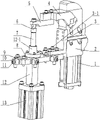
Fig. 1 is the structural representation of this adjustable soldering set.
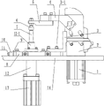
Fig. 2 is the schematic diagram on welding bench that is installed on of this adjustable soldering set.
The specific embodiment
Below in conjunction with accompanying drawing embodiment, the utility model is described in further detail:
Adjustable soldering set shown in Fig. 1 and Fig. 2 mainly comprises the alignment pin 7, L shaped pressing plate 3 of portable plate 8, supporting workpiece, supporting seat 2, clamp arm 4, jacking cylinder 13, Connection Block 12 and limited block 10 with clamping cylinder 1, portable plate 8 and supporting seat 2 are arranged on welding bench 14, clamping cylinder 1 is fixedly installed in supporting seat 2, the upper articulation of supporting seat 2 has clamp arm 4, clamping cylinder 1 drives clamp arm 4 to rotate around pin joint, clamp arm 4 is connected with and is withheld 6 by contiguous block 5, withholds 6 and coordinates clamping work pieces with alignment pin 7, alignment pin 7 is vertically installed on portable plate 8, the upper surface of portable plate 8 arranges L shaped pressing plate 3, the riser of L shaped pressing plate 3 is fixedly connected on supporting seat 2, the flat board of L shaped pressing plate 3 is fixed portable plate 8 on welding bench 14 by clamping screw 3-1, the other limited block 10 that is provided with in adjacent two orthogonal side end faces of portable plate 8, limited block 10 is fixed on welding bench 14, portable plate 8 is connected with limited block 10 by adjusting bolt 11, between the side end face of limited block 10 and portable plate 8, be provided with the open washer 9 being connected in adjusting bolt 11, open washer 9 is arranged between limited block 10 and the side end face of portable plate 8, while regulating the horizontal level of portable plate 8, unclamp adjusting bolt 11, open washer 9 is taken out or increase new open washer 9, and then rotate backward adjusting bolt 11 and lock, it is worth mentioning that, on portable plate 8, be fixedly installed a connecting seat 12, the upper end of Connection Block 12 is provided with the guide pin bushing 12-1 of an insertion alignment pin 7, the lower end of Connection Block 12 is through portable plate 8 and welding bench 14 and be connected with a jacking cylinder 13, and the piston rod of jacking cylinder 13 stretches in guide pin bushing 12-1 and is connected with alignment pin 7.
Many covers adjustable soldering set of the present utility model can be set on welding bench 14, before welding, adjust horizontal level and the vertical position of the alignment pin 7 of each strong point according to the profile of workpiece, first unclamp the clamping screw 3-1 on L shaped pressing plate 3, make portable plate 8 in state that can be movable, regulate respectively again the regulating part of 8 two perpendicular side end faces of portable plate can change the position of portable plate in X-direction and Y direction, and alignment pin 7 move on horizontal plane with portable plate 8; Alignment pin 7, in the position of Z-direction, is controlled by jacking cylinder 13.After the alignment pin 7 of each strong point is all debugged and is put in place, workpiece is positioned on the bracing frame being formed by multiple alignment pins 7, start clamping cylinder 1, drive clamp arm 4 to press down, until withhold 6 by Work-sheet pressing on alignment pin 7, can start weld job, its welding precision is high, constant product quality.
Claims (3)
1. an adjustable soldering set, comprise the alignment pin for supporting workpiece, it is characterized in that: described alignment pin is installed on a portable plate, the upper surface of described portable plate is provided with a L shaped pressing plate, the flat board of described L shaped pressing plate is fixed described portable plate on welding bench by clamping screw, the riser of described L shaped pressing plate is fixedly connected on a supporting seat having with clamping cylinder, on described supporting seat, be hinged with by described clamping cylinder and drive the clamp arm rotating, described clamp arm is connected with the head of withholding with described alignment pin compression fit; At the other limited block being fixed on described welding bench that is provided with at least one side end face of described portable plate, described portable plate is connected with described limited block by adjusting bolt, between described limited block and the side end face of described portable plate, is provided with the open washer being connected in described adjusting bolt.
2. adjustable soldering set according to claim 1, it is characterized in that: on described portable plate, be equipped with a connecting seat, the upper end of described Connection Block is provided with the guide pin bushing of the described alignment pin of an insertion, the lower end of described Connection Block is fixed with a jacking cylinder, and the piston rod of described jacking cylinder stretches in described guide pin bushing and is connected with described alignment pin.
3. adjustable soldering set according to claim 1 and 2, is characterized in that: two perpendicular sides, side end faces of described portable plate are provided with described limited block.
Priority Applications (1)
| Application Number | Priority Date | Filing Date | Title |
|---|---|---|---|
| CN201320847432.7U CN203679592U (en) | 2013-12-21 | 2013-12-21 | Adjustable welding tool |
Applications Claiming Priority (1)
| Application Number | Priority Date | Filing Date | Title |
|---|---|---|---|
| CN201320847432.7U CN203679592U (en) | 2013-12-21 | 2013-12-21 | Adjustable welding tool |
Publications (1)
| Publication Number | Publication Date |
|---|---|
| CN203679592U true CN203679592U (en) | 2014-07-02 |
Family
ID=51001551
Family Applications (1)
| Application Number | Title | Priority Date | Filing Date |
|---|---|---|---|
| CN201320847432.7U Withdrawn - After Issue CN203679592U (en) | 2013-12-21 | 2013-12-21 | Adjustable welding tool |
Country Status (1)
| Country | Link |
|---|---|
| CN (1) | CN203679592U (en) |
Cited By (6)
| Publication number | Priority date | Publication date | Assignee | Title |
|---|---|---|---|---|
| CN104128733A (en) * | 2013-12-21 | 2014-11-05 | 柳州万众汽车部件有限公司 | Adjustable welding set |
| CN104985380A (en) * | 2015-08-04 | 2015-10-21 | 王琼琦 | Welding tool with cooling structure |
| CN104985372A (en) * | 2015-07-08 | 2015-10-21 | 力帆实业(集团)股份有限公司 | Headstock pipe positioning device of motorcycle frame welding tool |
| CN110026726A (en) * | 2019-05-21 | 2019-07-19 | 山东大学 | A kind of Self adapting fixture system and working method avoiding vehicle body parts clamping deformation |
| CN111097997A (en) * | 2018-10-25 | 2020-05-05 | 宁波方太厨具有限公司 | Tool for welding internal corner at groove step |
| CN111331301A (en) * | 2020-03-09 | 2020-06-26 | 东风柳州汽车有限公司 | Rotary track pressing device of cross sliding table |
-
2013
- 2013-12-21 CN CN201320847432.7U patent/CN203679592U/en not_active Withdrawn - After Issue
Cited By (10)
| Publication number | Priority date | Publication date | Assignee | Title |
|---|---|---|---|---|
| CN104128733A (en) * | 2013-12-21 | 2014-11-05 | 柳州万众汽车部件有限公司 | Adjustable welding set |
| CN104128733B (en) * | 2013-12-21 | 2017-03-22 | 柳州万众汽车部件有限公司 | Adjustable welding set |
| CN104985372A (en) * | 2015-07-08 | 2015-10-21 | 力帆实业(集团)股份有限公司 | Headstock pipe positioning device of motorcycle frame welding tool |
| CN104985372B (en) * | 2015-07-08 | 2016-09-14 | 力帆实业(集团)股份有限公司 | Frame of motorcycle welding tooling head tube positioner |
| CN104985380A (en) * | 2015-08-04 | 2015-10-21 | 王琼琦 | Welding tool with cooling structure |
| CN104985380B (en) * | 2015-08-04 | 2016-08-24 | 谭柳 | Welding fixture with cooling structure |
| CN111097997A (en) * | 2018-10-25 | 2020-05-05 | 宁波方太厨具有限公司 | Tool for welding internal corner at groove step |
| CN110026726A (en) * | 2019-05-21 | 2019-07-19 | 山东大学 | A kind of Self adapting fixture system and working method avoiding vehicle body parts clamping deformation |
| CN110026726B (en) * | 2019-05-21 | 2024-06-18 | 山东大学 | Self-adaptive clamp system for avoiding clamping deformation of vehicle body parts and working method |
| CN111331301A (en) * | 2020-03-09 | 2020-06-26 | 东风柳州汽车有限公司 | Rotary track pressing device of cross sliding table |
Similar Documents
| Publication | Publication Date | Title |
|---|---|---|
| CN104128733B (en) | Adjustable welding set | |
| CN203679592U (en) | Adjustable welding tool | |
| CN107138899B (en) | Welding positioning tool table for aluminum alloy templates | |
| CN203156263U (en) | Welding fixture device for automobile radiator lower cross beam | |
| CN207681966U (en) | A kind of boring precise positioning fixture | |
| CN202088135U (en) | Assembling fixture | |
| CN104015078B (en) | A kind of one-tenth blank mould mould faying face fixture | |
| CN217727675U (en) | Clamp of automatic welding equipment for aluminum template | |
| CN202655837U (en) | Rotary assembly for welding apron board grid of railway vehicle | |
| CN201960301U (en) | Fast compactor | |
| CN213002414U (en) | Shaft part thread rolling positioning device | |
| CN203292742U (en) | Welding clamp of auxiliary frame | |
| CN108788843B (en) | Positioning and clamping device for machining marine diesel engine connecting rod | |
| CN218695646U (en) | Automatic welding, clamping and shifting tool for large plate structural member | |
| CN205630062U (en) | Automatic change many categories clamping system and digit control machine tool | |
| CN214921742U (en) | Hinge scraper blade spare part assembly welding frock | |
| CN103753077A (en) | Positioning device for frame side beam | |
| CN203804589U (en) | Automatic clamping device with side direction positioning | |
| CN208409004U (en) | A kind of automobile rear-wheel cover seal plate welding assembly welding clamp | |
| CN207593140U (en) | Suitable for the joint welding tooling of working at height vehicle carriage | |
| CN106002343A (en) | Elastic bracket for revolving body workpiece | |
| CN209288614U (en) | A kind of automobile production positioning device for welding | |
| CN111015314A (en) | CNC machine tool mounting fixture | |
| CN106312601B (en) | Swing clamp cylinder lever promotes clamp system | |
| CN205415079U (en) | Quick aligning device of large -scale work piece |
Legal Events
| Date | Code | Title | Description |
|---|---|---|---|
| C14 | Grant of patent or utility model | ||
| GR01 | Patent grant | ||
| AV01 | Patent right actively abandoned |
Granted publication date: 20140702 Effective date of abandoning: 20170322 |
|
| C25 | Abandonment of patent right or utility model to avoid double patenting |