Automatic assembly machine with tool magazine
Technical Field
The utility model relates to the technical field of automatic assembly, in particular to an automatic assembly machine with a tool magazine.
Background
With the progress of machinery and industry, the assembly precision required in various assembly fields is continuously improved, many manual assemblies cannot meet the precision requirement of products, manual physical consumption is high in some large-scale assemblies, and meanwhile, the improvement of labor intensity forms a bottleneck for the production quality and yield.
At present, technical personnel in the assembly field mostly adopt the hot charge or the manual work uses the frock to carry out pressure assembly, and the hot charge can greatly influence the uniformity of product, and staff's physical power also can consume and greatly cause work efficiency to descend, and the manual work uses the frock to carry out pressure assembly and has solved the uniformity of pressure, but can be high to the requirement of assembler to technology and frock.
SUMMERY OF THE UTILITY MODEL
The utility model aims to provide an automatic assembling machine with a tool magazine, which aims to solve the problems in the background technology.
In order to achieve the purpose, the utility model provides the following technical scheme: an automatic assembling machine with a tool magazine comprises a base, wherein a first guide column and a second guide column are fixedly arranged on the base, an upper beam is arranged above the base, a first guide sleeve and a second guide sleeve are respectively and fixedly arranged at the two ends of the upper beam, the first guide sleeve is sleeved with the first guide post in a sliding manner, the second guide sleeve is sleeved with the second guide post in a sliding manner, the first guide post is provided with two tool warehouse mechanisms for placing tools, the two tool warehouse mechanisms are distributed up and down, the upper beam is provided with an upper tool grabbing mechanism for grabbing tools from a tool warehouse mechanism positioned above, the base is provided with a lower tool grabbing mechanism for grabbing tools from a tool warehouse mechanism positioned below the base, the fixture is characterized in that a tool fixture is arranged on the second guide pillar, a lifting mechanism for driving the tool fixture to lift and a swing mechanism for driving the tool fixture to rotate are arranged on the second guide pillar.
Optionally, the tool magazine mechanism includes a positioning guide sleeve and a limiting guide sleeve fixedly arranged on the first guide pillar, a first shaft sleeve is fixedly arranged on the positioning guide sleeve, a second shaft sleeve is rotatably matched with the first shaft sleeve, a disc gear is fixedly arranged on the second shaft sleeve, a tool carrier for placing a tool is fixedly arranged on the disc gear, a gasket is arranged between the limiting guide sleeve and the second shaft sleeve, the gasket is sleeved on the first guide pillar, a first motor support is fixedly arranged on the positioning guide sleeve, a rotating motor is fixedly arranged on the first motor support, a circular gear is fixedly arranged on an output shaft of the rotating motor, and the circular gear is meshed with the disc gear.
Optionally, the upper tool grabbing mechanism comprises a translation plate, a first synchronous belt linear module used for driving the translation plate to move linearly is arranged on the upper beam, rollers are fixedly arranged on the translation plate, linear transverse rails used for supporting the rollers to move linearly are fixedly arranged on the upper beam, a pressure oil cylinder is fixedly arranged on the translation plate, a longitudinal moving block is fixedly arranged on a piston rod of the pressure oil cylinder, a first grabbing manipulator is fixedly arranged on the longitudinal moving block, a polished rod is fixedly arranged on the longitudinal moving block, and the polished rod penetrates through the translation plate.
Optionally, the first grabbing manipulator comprises a connecting block fixedly arranged on the longitudinal moving block, a grabbing device is fixedly arranged on the connecting block, a clamping groove is formed in the center of the bottom of the grabbing device, two steel ball grooves communicated with the clamping groove are formed in the grabbing device, steel balls are arranged in the two steel ball grooves, and an air cylinder piston rod used for pushing the steel balls into the clamping groove is arranged on the grabbing device.
Optionally, the lower tool grabbing mechanism comprises a linear guide rail fixedly arranged on the base, an air cushion slider in sliding fit with the linear guide rail, a slider support fixedly arranged on the air cushion slider, a second grabbing manipulator fixedly arranged on the slider support, and a second synchronous belt linear module fixedly arranged on the base and used for driving the air cushion slider to move linearly.
Optionally, the second grabbing mechanical arm comprises a cylinder support fixedly arranged on the sliding block support, a lifting cylinder is fixedly arranged on the cylinder support, clamping fingers are fixedly arranged on a piston rod of the lifting cylinder, clamping jaws are fixedly arranged on the clamping fingers, and the clamping fingers are provided with two groups, wherein the two groups are fixedly connected with electric push rods.
Optionally, the lifting mechanism includes four pillars that are rectangular distribution, the pillar activity runs through the second guide pin bushing, the bottom of pillar has set firmly the bottom plate, just the top of pillar has set firmly the roof, the lift cylinder has set firmly on the roof, the piston rod fixed connection of lift cylinder the second guide pillar, the periphery cover of second guide pillar is equipped with the supporting sleeve, frock clamp has set firmly on the supporting sleeve, just the top integrated into one piece of supporting sleeve has the expansion portion, the circular through-hole that is used for holding the expansion portion passes through is seted up to the bottom plate, be equipped with on the bottom plate rotation mechanism.
Optionally, the swing mechanism includes a swing gear fixedly connected to the expansion portion through a bolt, a second motor support fixedly disposed on the pillar, a hydraulic motor fixedly disposed on the second motor support, and a driving gear fixedly disposed on an output shaft of the hydraulic motor and engaged with the swing gear.
Optionally, the bottom plate is fixedly provided with a roller shaft through a set screw, the roller shaft is rotationally matched with a rotating wheel, the rotating wheel is in rolling fit with the lower surface of the rotary gear, and the bottom plate is provided with a cylindrical hole for accommodating the roller shaft and a cake hole for accommodating the roller.
Optionally, a third shaft sleeve is fixedly arranged on the inner wall of the rotary gear and the inner wall of the bottom of the supporting sleeve, and the third shaft sleeve is rotatably matched with the second guide pillar.
Compared with the prior art, the utility model provides an automatic assembling machine with a tool library, which has the following beneficial effects:
1. according to the multi-degree-of-freedom tooling fixture, the multi-degree-of-freedom operation of the tooling fixture is completed through the lifting mechanism and the rotating mechanism, the required tooling is automatically rotated to the gripping position through the linkage of the tooling warehouse mechanism, the upper tooling gripping mechanism and the lower tooling gripping mechanism, the heavy body force work carried by an operator is solved, the high-precision positioning is also completed, and a good foundation is provided for assembly;
2. according to the clamping tool, the first grabbing manipulator controls the driving force generated by the expansion of the cylinder piston rod through external pneumatic force to push the steel ball part into the clamping groove, the base tail handle of the clamping tool is stabilized, the second grabbing manipulator drives the clamping jaw to buckle the tool through the lifting cylinder, the clamping tool and the slider support are jointly stabilized, the tool can be pushed out of the second grabbing manipulator through the electric push rod, and the tool is convenient to feed.
Drawings
FIG. 1 is a schematic structural view of the present invention as a whole;
FIG. 2 is a partial cross-sectional view of the tool magazine mechanism of the present invention;
FIG. 3 is a schematic structural view of an upper tooling gripping mechanism according to the present invention;
FIG. 4 is a schematic structural view of a lower tooling gripping mechanism according to the present invention;
FIG. 5 is a schematic diagram of the construction of the lifting mechanism and swing mechanism of the present invention;
FIG. 6 is a cross-sectional view of the base plate, bearing housing and rotary gear of the present invention;
FIG. 7 is a schematic structural view of a first grasping robot according to the present invention;
fig. 8 is a schematic structural view of a second grasping robot in the present invention.
In the figure: 1. a base; 2. an upper beam; 3. a first guide post; 4. a second guide post; 5. a first guide sleeve; 6. a second guide sleeve; 7. a tool magazine mechanism; 8. an upper tool grabbing mechanism; 9. a lower tool grabbing mechanism; 10. a tooling fixture; 11. a lifting mechanism; 12. a swing mechanism; 13. positioning the guide sleeve; 14. a limiting guide sleeve; 15. a first bushing; 16. a second shaft sleeve; 17. a disc gear; 18. a tooling carrier; 19. a gasket; 20. a first motor bracket; 21. a rotating electric machine; 22. a circular gear; 23. a translation plate; 24. a first synchronous belt linear module; 25. a roller; 26. a linear transverse rail; 27. a pressure oil cylinder; 28. longitudinally moving the block; 29. a first grabbing manipulator; 30. a polish rod; 31. a linear guide rail; 32. an air cushion slide block; 33. a slider bracket; 34. a second grabbing manipulator; 35. a second synchronous belt linear module; 36. a pillar; 37. a base plate; 38. a top plate; 39. lifting the oil cylinder; 40. a support sleeve; 41. an expansion section; 42. a circular through hole; 43. a cylindrical bore; 44. a cake hole; 45. a rotary gear; 46. a second motor support; 47. a hydraulic motor; 48. a drive gear; 49. a roll shaft; 50. a rotating wheel; 51. a third shaft sleeve; 52. a cylinder support; 53. a lifting cylinder; 54. clamping fingers; 55. a clamping jaw; 56. an electric push rod; 57. connecting blocks; 58. a gripper; 59. a clamping groove; 60. a steel bead groove; 61. steel balls; 62. and a cylinder piston rod.
Detailed Description
The technical solutions in the embodiments of the present invention will be clearly and completely described below with reference to the drawings in the embodiments of the present invention, and it is obvious that the described embodiments are only a part of the embodiments of the present invention, and not all of the embodiments. All other embodiments, which can be derived by a person skilled in the art from the embodiments given herein without making any creative effort, shall fall within the protection scope of the present invention.
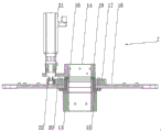
Example (b): referring to fig. 1, the utility model provides an automatic assembling machine with a tool magazine, which includes a base 1, a first guide post 3 and a second guide post 4 are fixedly mounted on the base 1 through bolts, an upper beam 2 is arranged above the base 1, a first guide sleeve 5 and a second guide sleeve 6 are respectively fixedly mounted at two ends of the upper beam 2 through bolts, the first guide sleeve 5 is in sliding sleeve connection with the first guide post 3, and the second guide sleeve 6 is in sliding sleeve connection with the second guide post 4. Be equipped with the frock storehouse mechanism 7 that is used for placing the frock on first guide pillar 3, frock storehouse mechanism 7 is equipped with two and is upper and lower distribution, is equipped with on the upper beam 2 to be used for snatching the last frock of frock and snatchs mechanism 8 from the frock storehouse mechanism 7 that is located the top, is equipped with on the base 1 to be used for snatching the lower frock of frock and snatchs mechanism 9 from the frock storehouse mechanism 7 that is located the below. The second guide pillar 4 is provided with a tooling fixture 10, and the second guide pillar 4 is provided with a lifting mechanism 11 for driving the tooling fixture 10 to ascend and descend and a swing mechanism 12 for driving the tooling fixture 10 to rotate.
Referring to fig. 2, the tool magazine mechanism 7 includes a positioning guide sleeve 13 and a limiting guide sleeve 14 fixed on the first guide post 3 through a set screw, a first shaft sleeve 15 is fixed on the positioning guide sleeve 13 through a set screw, a second shaft sleeve 16 is rotatably matched with the first shaft sleeve 15, a disc gear 17 is fixed on the second shaft sleeve 16 through a set screw, and a tool carrier 18 for placing a tool is fixed on the disc gear 17. A washer 19 is arranged between the limiting guide sleeve 14 and the second shaft sleeve 16, and the washer 19 is sleeved on the first guide pillar 3. A first motor support 20 is integrally formed on the positioning guide sleeve 13, a rotating motor 21 is fixedly mounted on the first motor support 20 through a bolt, an output shaft of the rotating motor 21 is in keyed connection with a circular gear 22, and the circular gear 22 is meshed with the disc gear 17.
In the tool magazine mechanism 7, the tool carrier 18 drives the gear set formed by the circular gear 22 and the disc gear 17 through the rotating motor 21 to rotate around the first guide post 3, and an encoder can be installed on the rotating motor 21, so that the output angular displacement of the rotating motor 21 is a constant value, and the tool on the tool carrier 18 is aligned with the first grabbing manipulator 29 and the second grabbing manipulator 34.
Referring to fig. 3, the upper tooling grabbing mechanism 8 includes a translation plate 23, a first synchronous belt linear module 24 for driving the translation plate 23 to move linearly is arranged on the upper beam 2, a roller 25 is fixedly mounted on the translation plate 23 through a bolt, a linear transverse rail 26 for supporting the roller 25 to move linearly is fixedly mounted on the upper beam 2 through a bolt, a pressure cylinder 27 is fixedly mounted on the translation plate 23 through a bolt, a longitudinal moving block 28 is fixedly mounted on a piston rod of the pressure cylinder 27 through a bolt, a first grabbing manipulator 29 is fixedly mounted on the longitudinal moving block 28 through a bolt, a polish rod 30 is fixedly mounted on the longitudinal moving block 28 through a bolt, and the polish rod 30 penetrates through the translation plate 23. The upper beam 2 is provided with a displacement ruler, and the stroke of the first synchronous belt linear module 24 is controlled by the displacement ruler. The tool held by the first gripper robot 29 can be pressed into the housing of the speed reducer or the motor to be transferred by the driving force generated by the pressure cylinder 27.
Referring to fig. 7, the first grabbing manipulator 29 includes a connecting block 57 mounted on the longitudinal moving block 28 through a bolt, a grabbing device 58 is mounted on the connecting block through a bolt, a clamping groove 59 is formed in the center of the bottom of the grabbing device 58, two steel ball grooves 60 communicated with the clamping groove 59 are formed in the grabbing device 58, two steel balls 61 are disposed in each of the two steel ball grooves 60, and a cylinder piston rod 62 for partially pushing the steel ball 61 into the clamping groove 59 is disposed on the grabbing device 58. The gripper 58 is provided with a cylinder groove for placing the cylinder piston rod 62, the gripper 58 is further provided with a through hole for communicating the cylinder groove, the cylinder groove and the cylinder piston rod 62 are combined into a single-acting cylinder, and the two cylinder piston rods 62 can be controlled to synchronously run through one cylinder control system. The bottom of the cylinder piston rod 62 is provided with an arc-shaped groove matched with the steel ball 61. Initially, the stroke of the cylinder piston rod 62 is zero, one steel ball 61 abuts against the cylindrical outer wall of the non-arc-shaped groove on the cylinder piston rod 62, and the other steel ball 61 partially extends into the clamping groove 59, so that the steel ball closest to the clamping groove 59 in the two steel ball grooves 60 can clamp the base tail handle of the tool in an aligned manner; when the stroke of the cylinder piston rod 62 reaches the maximum, the two steel balls 61 are both positioned in the steel ball groove 60, one of the steel balls 61 is embedded in the arc-shaped groove on the cylinder piston rod 62, and the steel ball 61 no longer clamps the basal body tail handle of the tool. The rod section periphery cover of cylinder piston rod 62 is equipped with compression spring, and compression spring's both ends respectively with the piston section of cylinder piston rod 62 and the inner wall looks butt that is close to the cylinder groove bottom on the gripper 58, utilize the restoring force that compression spring provided for cylinder piston rod 62 still can get back to initial condition when losing external aerodynamic force, realizes that steel ball 61 stabilizes the centre gripping work piece.
Referring to fig. 4, the lower tooling grabbing mechanism 9 includes a linear guide rail 31 fixedly mounted on the base 1 through a bolt, an air cushion slider 32 slidably fitted to the linear guide rail 31, a slider bracket 33 fixedly mounted on the air cushion slider 32 through a bolt, a second grabbing manipulator 34 fixedly mounted on the slider bracket 33 through a bolt, and a second synchronous belt linear module 35 fixedly mounted on the base 1 through a bolt and used for driving the air cushion slider 32 to move linearly. Wherein, the second snatchs manipulator 34 and chooses ninety degrees revolving cylinder for use, opens second snatchs manipulator 34 and is used for snatching the frock base member in the frock storehouse mechanism 7 that is located below. Install the displacement chi on the base 1, through the stroke of displacement chi control second hold-in range straight line module 35.
Referring to fig. 8, the second grabbing manipulator 34 includes a cylinder bracket 52 mounted on the slider bracket 33 through a bolt, a lifting cylinder 53 is mounted on the cylinder bracket 52 through a bolt, a piston rod of the lifting cylinder 53 is mounted with a clamping finger 54 through a bolt, a clamping jaw 55 is mounted on the clamping finger 54 through a bolt, two groups of clamping fingers 54 are provided, and an electric push rod 56 is fixedly connected to each group of clamping fingers 54 through a bolt. The lifting cylinder 53 adopts a conventional single-acting cylinder, the electric push rod 56 adopts a conventional ball screw type electric telescopic rod, the lifting cylinder 53 is opened, the piston rod of the lifting cylinder 53 realizes the upward movement or the downward movement of the clamping jaw 55 by pushing the clamping finger 54, so that the clamping jaw 55 is buckled with a groove on the tool, and the clamping tool is realized. The lifting cylinder 53 is firstly opened to enable the clamping jaw 55 to be separated from the work, and then the electric push rod 56 is opened, so that the tool can be ejected out of the second grabbing mechanical arm 34.
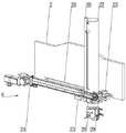
Referring to fig. 5, the lifting mechanism 11 includes four pillars 36 distributed in a rectangular shape, the pillars 36 movably penetrate through the second guide sleeve 6, a bottom plate 37 is fixedly mounted at the bottom end of the pillar 36 through a bolt, a top plate 38 is fixedly mounted at the top end of the pillar 36 through a bolt, a lifting cylinder 39 is fixedly mounted on the top plate 38 through a bolt, a piston rod of the lifting cylinder 39 is fixedly connected to the second pillar 4 through a bolt, a supporting sleeve 40 is sleeved on the outer periphery of the second pillar 4, a tooling fixture 10 is fixedly mounted on the supporting sleeve 40 through a bolt, and the tooling fixture 10 is used for clamping a speed reducer housing or a motor housing. The lifting oil cylinder 39 is provided with a displacement ruler, and the stroke of the lifting oil cylinder 39 is controlled by the displacement ruler. An expansion part 41 is integrally formed at the top end of the support sleeve 40, a circular through hole 42 for accommodating the expansion part 41 to pass through is opened on the bottom plate 37, and the rotating mechanism 12 is arranged on the bottom plate 37.
The swing mechanism 12 includes a swing gear 45 fixedly coupled to the expanding portion 41 by bolts, a second motor bracket 46 mounted to the column 36 by bolts, a hydraulic motor 47 mounted to the second motor bracket 46 by bolts, and a drive gear 48 welded to an output shaft of the hydraulic motor 47 and engaged with the swing gear 45.
Referring to fig. 6, a roller shaft 49 is fixedly arranged on the bottom plate 37 through a set screw, a rotating wheel 50 is rotatably matched with the roller shaft 49, the rotating wheel 50 is in rolling fit with the lower surface of the rotary gear 45, and a cylindrical hole 43 for accommodating the roller shaft 49 and a cake hole 44 for accommodating the roller 25 are formed in the bottom plate 37. The inner wall of slewing gear 45 and the bottom inner wall of supporting sleeve 40 all have third axle sleeve 51 through bolt fixed mounting, through third axle sleeve 51 normal running fit second guide pillar 4, avoid slewing gear 45 and second guide pillar 4 on the one hand to and take place wearing and tearing between supporting sleeve 40 and the second guide pillar 4, on the other hand reduces the sliding friction area, makes supporting sleeve 40 go up and down and the gyration is more steady smooth.
Although embodiments of the present invention have been shown and described, it will be appreciated by those skilled in the art that changes, modifications, substitutions and alterations can be made in these embodiments without departing from the principles and spirit of the utility model, the scope of which is defined in the appended claims and their equivalents.