CN215911454U - Diaphragm overturning and coating lamination mechanism - Google Patents
Diaphragm overturning and coating lamination mechanism Download PDFInfo
- Publication number
- CN215911454U CN215911454U CN202121129107.8U CN202121129107U CN215911454U CN 215911454 U CN215911454 U CN 215911454U CN 202121129107 U CN202121129107 U CN 202121129107U CN 215911454 U CN215911454 U CN 215911454U
- Authority
- CN
- China
- Prior art keywords
- diaphragm
- lamination
- overturning
- pole piece
- membrane
- Prior art date
- Legal status (The legal status is an assumption and is not a legal conclusion. Google has not performed a legal analysis and makes no representation as to the accuracy of the status listed.)
- Active
Links
Images


Classifications
-
- Y—GENERAL TAGGING OF NEW TECHNOLOGICAL DEVELOPMENTS; GENERAL TAGGING OF CROSS-SECTIONAL TECHNOLOGIES SPANNING OVER SEVERAL SECTIONS OF THE IPC; TECHNICAL SUBJECTS COVERED BY FORMER USPC CROSS-REFERENCE ART COLLECTIONS [XRACs] AND DIGESTS
- Y02—TECHNOLOGIES OR APPLICATIONS FOR MITIGATION OR ADAPTATION AGAINST CLIMATE CHANGE
- Y02E—REDUCTION OF GREENHOUSE GAS [GHG] EMISSIONS, RELATED TO ENERGY GENERATION, TRANSMISSION OR DISTRIBUTION
- Y02E60/00—Enabling technologies; Technologies with a potential or indirect contribution to GHG emissions mitigation
- Y02E60/10—Energy storage using batteries
-
- Y—GENERAL TAGGING OF NEW TECHNOLOGICAL DEVELOPMENTS; GENERAL TAGGING OF CROSS-SECTIONAL TECHNOLOGIES SPANNING OVER SEVERAL SECTIONS OF THE IPC; TECHNICAL SUBJECTS COVERED BY FORMER USPC CROSS-REFERENCE ART COLLECTIONS [XRACs] AND DIGESTS
- Y02—TECHNOLOGIES OR APPLICATIONS FOR MITIGATION OR ADAPTATION AGAINST CLIMATE CHANGE
- Y02P—CLIMATE CHANGE MITIGATION TECHNOLOGIES IN THE PRODUCTION OR PROCESSING OF GOODS
- Y02P70/00—Climate change mitigation technologies in the production process for final industrial or consumer products
- Y02P70/50—Manufacturing or production processes characterised by the final manufactured product
Landscapes
- Primary Cells (AREA)
- Secondary Cells (AREA)
Abstract
The utility model provides a lamination mechanism for turning and coating a diaphragm. The lamination mechanism comprises a lamination table, a blanking assembly and a diaphragm overturning and coating assembly; the blanking assembly can move close to or far away from the lamination table; the membrane overturning and coating assembly comprises a fixed supporting plate and an overturning suction plate which is movably connected to the end part of the fixed supporting plate, close to the lamination table, and can movably overturn to press the cover on the fixed supporting plate. After the last pole piece of the pole piece electric core is stacked on the lamination table, the pole piece electric core can be transferred to a fixed supporting plate of the diaphragm overturning and coating assembly while stretching the diaphragm, and after the stretched diaphragm is cut off, the cut diaphragm is coated on the surface of the last pole piece of the pole piece electric core by the overturning and sucking plate; meanwhile, the diaphragm on the lamination table can be pressed and positioned, and the first pole piece of the next pole piece battery cell is synchronously laminated. Therefore, the auxiliary time between the stacking procedures of the two pole piece battery cores is greatly shortened, and the production efficiency is improved.
Description
Technical Field
The utility model relates to the technical field of battery cell production equipment, in particular to a lamination mechanism for turning and coating a diaphragm.
Background
The lamination is an important production mode of a lithium battery pole piece electric core, in the production process of the mode, a lamination device is adopted to alternately laminate positive pole pieces and negative pole pieces, and the alternately laminated positive and negative pole pieces are coated and separated by an unreeled diaphragm. In the pole piece battery cell finished by lamination production, the upper side and the lower side of the battery cell are finally coated by the diaphragm.
At present, for a pole piece electric core which does not need tail coiling, the lamination device and the production thereof have the process requirement that only one layer of diaphragm is pasted on the surface of the last negative plate of the pole piece electric core, specifically, after the last negative plate is laminated, the lamination table moves to the side close to the blanking side again, the blanking mechanism grabs the electric core on the lamination table to move and stretch the diaphragm, then the diaphragm is cut off, and the diaphragm is blown to the surface of the last negative plate by the air blowing pipe. In the meantime, the lamination table needs to be moved to the blanking side again, which increases the time consumption; in addition, in the process of cutting and applying the diaphragm on the surface of the last negative plate, the lamination process of the next pole piece battery cell cannot be carried out, the diaphragm needs to be pressed and positioned again by the pressing claw outside the lamination table after the cutting and applying of the diaphragm to the surface of the last negative plate are finished, then the first negative plate of the next pole piece battery cell is stacked, the auxiliary time of the whole transition process is long, and the working condition efficiency of the lamination device is seriously influenced.
SUMMERY OF THE UTILITY MODEL
In order to solve the problems of long lamination auxiliary time and low efficiency of the existing lamination device, the utility model provides a lamination mechanism for turning and coating a diaphragm, which can greatly reduce the lamination auxiliary time and has high lamination production efficiency.
The purpose of the utility model is realized by the following technical scheme.
A diaphragm overturning and coating lamination mechanism comprises a lamination table, a blanking assembly and a diaphragm overturning and coating assembly; the blanking assembly can move close to or far away from the lamination table;
the membrane overturning and coating assembly comprises a fixed supporting plate and an overturning suction plate; the overturning suction plate is movably connected to the end part, close to the lamination table, of the fixed supporting plate and can be movably overturned to press the fixed supporting plate; the fixed supporting plate and the overturning suction plate can be movably inserted into a position between the blanking assembly and the laminating table after being separated from each other.
In a preferred embodiment, the fixed supporting plate and the overturning suction plate are driven by a lifting cylinder to move upwards and deeply penetrate between the blanking assembly and the laminating table after being separated from each other.
In a preferred embodiment, the overturning suction plate is driven by a swinging cylinder to movably and overturns to press the fixed supporting plate.
In a preferred embodiment, the turnover suction plate is provided with a vacuum suction hole.
In a preferred embodiment, the blanking assembly comprises a blanking clamping jaw, and clamping jaw avoiding grooves are formed in the fixed supporting plate and the overturning suction plate; after the overturning suction plate is overturned and pressed on the fixed supporting plate, the clamping jaw avoiding groove on the overturning suction plate corresponds to the clamping jaw avoiding groove on the fixed supporting plate and corresponds to the blanking clamping jaw.
In a preferred embodiment, a second diaphragm pressing claw is arranged on the outer side of the fixed supporting plate; the second diaphragm pressing claw can move to the upper part of the fixed supporting plate along the width direction of the diaphragm.
In a more preferred embodiment, the second diaphragm pressing claw is provided so as to be movable in the width direction of the diaphragm to above the fixed blade by a pushing cylinder.
In a more preferred embodiment, the second diaphragm pressing claw is a cylinder pressing claw, and the pressing claw is driven by a cylinder to move downwards to press the pole piece battery core on the fixed supporting plate.
In a preferred embodiment, a first diaphragm pressing claw is arranged on the outer side of the lamination table; the first diaphragm pressing claw is movable in the width direction of the diaphragm to above the lamination stage.
In a more preferred embodiment, the first diaphragm pressing claw is a cylinder pressing claw, and the pressing claw is driven by a cylinder to move downwards to perform lamination pressing on the pole piece battery cell on the lamination table.
Further preferably, the first diaphragm pressing claws comprise at least four first diaphragm pressing claws distributed around the lamination table, and the at least four first diaphragm pressing claws can be linked to be closed or separated towards the lamination table.
In a preferred embodiment, the lamination table is slidably disposed on a movable slide rail, and can move along the movable slide rail to approach or separate from the blanking assembly.
In a more preferred embodiment, the lamination table is arranged on the movable sliding rail in a driving and sliding manner through the moving module. Further preferably, the lamination table is arranged on a base, a slide rail is arranged on the base, the first diaphragm pressing claw is arranged on the base in a sliding mode and can move to the position above the lamination table along the width direction of the diaphragm, and the base is arranged on the movable slide rail in a sliding mode.
In a preferred embodiment, in the lamination mechanism for membrane turnover coating of any one of the above, a membrane cutter assembly is correspondingly arranged at a joint of the turnover suction plate and the lamination table; the diaphragm cutter assembly includes a diaphragm cutter.
Compared with the prior art, the utility model has the following advantages and beneficial effects:
in the lamination mechanism, a diaphragm overturning and coating assembly is arranged between a lamination table and a blanking assembly, when the last pole piece of a pole piece cell is stacked on the lamination table, the pole piece cell can be transferred to a fixed supporting plate of the diaphragm overturning and coating assembly while stretching a diaphragm, and after the stretched diaphragm is cut off, the cut diaphragm is coated on the surface of the last pole piece of the pole piece cell by an overturning suction plate of the diaphragm overturning and coating assembly; meanwhile, the diaphragm on the lamination table can be pressed and positioned, and the first pole piece of the next pole piece cell is synchronously laminated in the process of cutting off the surface of the last pole piece of the pole piece cell coated by the diaphragm. Therefore, the diaphragm can be pasted on the last pole piece of the pole piece electric core, the auxiliary time between the stacking procedures of the two pole piece electric cores is greatly shortened, the working condition efficiency of the lamination device is exerted to the maximum extent, and the production efficiency is further improved.
Drawings
FIG. 1 is a schematic perspective view of a membrane inversion-wrapped lamination mechanism according to an embodiment of the present invention;
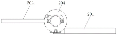
FIG. 2 is a schematic top view of a membrane inversion-wrapped lamination mechanism according to an embodiment of the present invention;
FIG. 3a, FIG. 3b, FIG. 3c are schematic structural views of the turnover suction plate respectively turning 0 °, 90 °, 180 ° relative to the fixed pallet;
FIG. 4 is a schematic diagram of a partial side view of a membrane inversion cladding assembly;
FIG. 5 is a schematic side view of the membrane inversion coating assembly cooperating with the blanking assembly;
FIG. 6 is a schematic illustration of the second diaphragm gripper in driving connection with a propulsion cylinder;
fig. 7 is a schematic structural diagram of pole piece cell lamination by using the lamination mechanism for membrane turnover coating of the present invention;
the attached drawings are marked as follows: 1-lamination assembly, 101-lamination table, 102-first membrane pressing claw, 103-movable sliding rail, 104-movable module, 2-membrane overturning coating assembly, 201-fixed supporting plate, 2011-first clamping jaw avoiding groove, 202-overturning suction plate, 2021-vacuum adsorption hole, 2022-second clamping jaw avoiding groove, 203-lifting cylinder, 204-swinging cylinder, 205-second membrane pressing claw, 206-propulsion cylinder, 3-blanking assembly, 301-blanking clamping jaw, 4-membrane cutter assembly, 401-membrane cutter, 5-positive plate, 6-negative plate, 7-membrane and 8-adhesive tape.
Detailed Description
The technical solutions of the present invention are further described in detail below with reference to specific examples and drawings, but the scope and implementation of the present invention are not limited thereto.
In the description of the specific embodiments, it should be noted that the terms "front", "back", "left", "right", and the like, indicate orientations or positional relationships based on the orientations or positional relationships shown in the drawings or orientations or positional relationships where the products of the utility model are usually placed when the products of the utility model are used, and the terms "first", "second", and the like, are used for distinguishing between the descriptions, and are used for convenience of describing and simplifying the description, but do not indicate or imply that the structures or elements that are referred to must have a specific orientation, be constructed in a specific orientation, and be operated, and therefore are not to be construed as limiting the utility model, and are not to indicate or imply relative importance.
Unless expressly stated or limited otherwise, the terms "mounted," "disposed," "connected," "secured," and the like are to be construed broadly and can include, for example, fixed connections, removable connections, or integral connections; can be mechanically or electrically connected; either directly or indirectly through intervening media, either internally or in any other relationship. The specific meaning of the above terms in the present application can be understood by those of ordinary skill in the art as appropriate.
The membrane overturning and coating lamination mechanism disclosed by the utility model is shown in figures 1 and 2 and comprises a lamination assembly 1, a blanking assembly 3 and a membrane overturning and coating assembly 2.
The lamination assembly 1 comprises a lamination table 101 as a main lamination station, and positive and negative pole pieces are alternately laminated and a diaphragm is coated on the lamination table 101 when pole pieces and cells are laminated.
Specifically, the lamination table 101 is a stacking platform, and a first diaphragm pressing claw 102 is arranged on the outer side of the lamination table 101; optionally, the first diaphragm pressing claw 102 is an air cylinder pressing claw, and the pressing claw is driven by an air cylinder to move downwards to perform lamination pressing on the pole piece electric core on the lamination table 101. Further, the first diaphragm pressing claw 102 is slidably disposed outside the lamination table 101, and the first diaphragm pressing claw 102 is movable in the width direction of the diaphragm to above the lamination table 101, that is, from the width direction of the diaphragm to above the lamination table 101, so that the alternately stacked pole pieces and diaphragms can be pressed from the front-back direction of the lamination table 101 when lamination is performed. In the specific embodiment shown, the first diaphragm pressing claws 102 include at least four first diaphragm pressing claws 102 distributed around the lamination table 101, and the at least four first diaphragm pressing claws 102 can be moved toward or away from the lamination table 101 in a linked manner.
In addition, a membrane unwinding assembly (not shown) is disposed above the lamination station 101. According to the specific lamination operation, the lamination table 101 can be selectively designed to reciprocate in the left-right direction for lamination and realize membrane coating, or the membrane unreeling assembly can be designed to reciprocate in the left-right direction for lamination and membrane coating. In the embodiment specifically shown in fig. 1 and 2, the lamination stage 101 is designed to reciprocate in the left-right direction.
The lamination table 101 is slidably disposed on a movable slide rail 103, and can move along the movable slide rail 103 to approach or depart from the blanking assembly 3. Specifically, the lamination table 101 is slidably disposed on the movable slide rail 103 through the driving of the moving module 104.
In a preferred embodiment, the lamination table 101 is disposed on a base, and a slide rail is disposed on the base, the first diaphragm pressing claw 102 is slidably disposed on the base and can move to above the lamination table 101 along the width direction of the diaphragm, and the base is slidably disposed on the movable slide rail 103.
Therefore, when lamination is carried out, the diaphragm is positioned and pressed on the lamination table 101 through the first diaphragm pressing claw 102 after being unreeled, then the feeding mechanism feeds positive and negative pole pieces onto the lamination table 101 alternately along with the reciprocating movement of the lamination table 101, and the diaphragm is unreeled and alternately coats the positive and negative pole pieces in the alternate feeding and laminating process of the positive and negative pole pieces, so that lamination is realized.
Further, the blanking assembly 3 can move close to or away from the lamination station 101. Specifically, referring to fig. 1 and fig. 2 again, the blanking assembly 3 includes a blanking clamping jaw 301, and an original position of the blanking clamping jaw 301 is located at a position far away from the lamination table 101. After the pole piece cells are laminated on the lamination table 101, the pole piece cells can be clamped by the blanking clamping jaws 301 from the lamination table 101 for blanking.
Referring to fig. 1 and 2 again, a membrane turnover wrapping assembly 2 is arranged between the lamination assembly 1 and the blanking assembly 3. After the last pole piece of the pole piece cell is stacked on the lamination table 101, the pole piece cell can be clamped and transferred to the diaphragm overturning and coating assembly 2 by the blanking clamping jaw 301, and meanwhile, the diaphragm is synchronously stretched; after the stretched diaphragm is cut off, the diaphragm overturning and coating assembly 2 coats the cut diaphragm on the surface of the last pole piece of the pole piece battery cell; meanwhile, the diaphragm on the lamination table 101 can be pressed and positioned, and the first pole piece of the next pole piece cell is laminated while the surface of the last pole piece of the pole piece cell coated by the diaphragm is cut off. Therefore, the diaphragm can be pasted on the last pole piece of the pole piece electric core, the auxiliary time between the stacking procedures of the two pole piece electric cores is greatly shortened, the working condition efficiency of the lamination device is exerted to the maximum extent, and the production efficiency is further improved.
Specifically, the membrane turnover cladding assembly 2 comprises a fixed supporting plate 201 and a turnover suction plate 202. Wherein, the fixed supporting plate 201 is positioned at one side close to the blanking assembly 3, and the overturning suction plate 202 is positioned at one side close to the laminated assembly 1; the turning suction plate 202 is movably connected to the end portion of the fixed pallet 201 close to the lamination table 101, and can be movably turned over and pressed on the fixed pallet 201, and please refer to fig. 3a to 3c, the turning suction plate 202 can be turned over by 0 to 180 degrees relative to the fixed pallet 201; and, the fixed pallet 201 and the turnover suction plate 202 can move deep into between the blanking assembly 3 and the lamination table 101 after being separated from each other.
And a diaphragm cutter assembly 4 is correspondingly arranged at the joint of the overturning suction plate 202 and the lamination table 101, specifically, the diaphragm cutter assembly 4 comprises a diaphragm cutter 401. The diaphragm cutter 401 arranged at the joint of the overturning suction plate 202 and the lamination table 101 can cut off the diaphragm stretching across the overturning suction plate 202 and the lamination table 101 so as to perform lamination coating of the next pole piece battery core.
Preferably, as shown in fig. 4, the fixed pallet 201 and the turnover suction plate 202 are driven by a lifting cylinder 203 to move upwards and deeply between the separated blanking assembly 3 and the lamination table 101, and the turnover suction plate 202 is driven by a swing cylinder 204 to movably and turnover cover the fixed pallet 201.
Furthermore, the inverted suction plate 202 is provided with a vacuum suction hole 2021. Optionally, the vacuum absorption hole 2021 is communicated with a vacuum extractor, and can generate a vacuum absorption effect when the vacuum extractor works.
Further, referring to fig. 1 and fig. 2 again, the fixed supporting plate 201 and the overturning suction plate 202 are both provided with a jaw avoiding groove, specifically, the fixed supporting plate 201 is provided with a first jaw avoiding groove 2011, and the overturning suction plate 202 is provided with a second jaw avoiding groove 2022; the upset gland of upset suction disc 202 is in back on the fixed support plate 201, the second clamping jaw on the upset suction disc 202 dodge the groove 2022 with the groove 2011 is dodged to the first clamping jaw on the fixed support plate 201 and corresponds each other, and with unloading clamping jaw 301 corresponds.
Thus, after the last pole piece of the pole piece cell is stacked on the lamination table 101, the pole piece cell can be clamped and transferred to a position far away from the lamination table 101 by the blanking clamping jaw 301, and the diaphragm is stretched; then, the fixed supporting plate 201 and the overturning suction plate 202 are driven by the lifting cylinder 203 to ascend to a position between the lamination assembly 1 and the blanking assembly 3, the blanking clamping jaws 301 clamp the pole piece battery cell and transfer the pole piece battery cell to the fixed supporting plate 201 for placement, and the stretched diaphragm covers the overturning suction plate 202. At this time, the vacuum pumping device works, the vacuum adsorption hole 2021 of the turnover suction plate 202 adsorbs and fixes the diaphragm, the diaphragm is cut off from the position where the turnover suction plate 202 is connected with the lamination table 101, the turnover suction plate 202 is turned over under the driving of the swing cylinder 204 and is pressed on the pole piece electric core arranged on the fixed support plate 201, so that the cut diaphragm is coated on the surface of the last pole piece of the pole piece electric core, and complete lamination of the electric core is realized; meanwhile, after the diaphragm is cut off, the diaphragm can be positioned and pressed on the lamination table 101 by the first diaphragm pressing claw 102 on the outer side of the lamination table 101, the next set of positive and negative pole pieces are alternately fed onto the lamination table 101 by the feeding mechanism, and the lamination table 101 starts to move left and right in a reciprocating manner to perform lamination of the next pole piece battery cell. After the coating of the cut-off separator is completed, please refer to fig. 5, the blanking clamping jaw 301 may correspondingly extend into the clamping jaw avoiding groove between the fixed supporting plate 201 and the turnover suction plate 202, and clamp and blank the pole piece battery cell from the fixed supporting plate 201.
In addition, referring to fig. 1 and 2 again, a second diaphragm pressing claw 205 is disposed on an outer side of the fixed supporting plate 201, and the second diaphragm pressing claw 205 can move above the fixed supporting plate 201 along a width direction of the diaphragm.
Specifically, as shown in fig. 6, the second diaphragm pressing claw 205 is a cylinder pressing claw, and the pressing claw is driven by a cylinder to move downward to press the pole piece electric core on the fixed supporting plate 201; and the second diaphragm pressing claw 205 is provided to be movable in the width direction of the diaphragm to above the fixed plate 201 by a pushing cylinder 206.
After the pole piece electric core is clamped and transferred onto the fixed supporting plate 201 by the blanking clamping jaw 301, the propulsion cylinder 206 can drive the second diaphragm pressing claw 205 to be close to the fixed supporting plate 201 along the front-back direction of the fixed supporting plate 201 and enable the pressing claw to move to the upper side of the fixed supporting plate 201, the second diaphragm pressing claw 205 presses down the pole piece electric core again to prevent unwinding, when the diaphragm to be cut off is coated on the surface of the last pole piece of the pole piece electric core, the second diaphragm pressing claw 205 releases the pressing of the pole piece electric core, and then the pole piece electric core is driven by the propulsion cylinder 206 to return to the initial station.
Example 1
The lamination mechanism for overturning and coating the diaphragm is adopted to laminate the pole piece battery cell, and the last pole piece of the pole piece battery cell is a negative pole piece, namely, a layer of diaphragm needs to be pasted on the surface of the last negative pole piece of the pole piece battery cell. Referring to fig. 7, in the lamination process, one side of the lamination assembly 1 close to the blanking assembly 3 is used as a negative plate feeding position, and the specific steps are as follows:
s1, unwinding the diaphragm, positioning and pressing the diaphragm by a first diaphragm pressing claw 102 and flatly laying the diaphragm on a lamination table 101, and moving the lamination table 101 and the first diaphragm pressing claw 102 to the right to be close to the blanking assembly 3; the feeding mechanism feeds the first negative plate 6 to the lamination table 101, and the bottom surface of the first negative plate is coated by the diaphragm 7 which is tiled on the lamination table 101; then, the lamination table 101 moves to the left side again, the diaphragm 7 is made to cover the upper surface of the first negative plate 6, and the first positive plate 5 is fed and laminated on the diaphragm 7;
the lamination table 101 moves left and right in a reciprocating manner to realize the alternate lamination of the positive plates 5 and the negative plates 6, and the diaphragm 7 is automatically unreeled to realize the layered coating of the positive plates 5 and the negative plates 6;
after the last negative plate 6 is loaded on the pole piece electric core, the blanking clamping jaw 301 clamps and transfers the pole piece electric core to a position far away from the lamination table 101, specifically, a position corresponding to the fixed supporting plate 201, and the diaphragm 7 is stretched in the transferring process.
S2, the fixed supporting plate 201 and the overturning suction plate 202 of the membrane overturning and coating assembly 2 are driven by the lifting cylinder 203 to ascend to a position between the laminated assembly 1 and the blanking assembly 3; the fixed supporting plate 201 corresponds to a tight-supporting pole piece battery cell, meanwhile, the vacuum adsorption hole 2021 on the overturning adsorption plate 202 generates an adsorption effect to adsorb and fix the stretched diaphragm 7, and the first diaphragm pressing claw 102 positions and presses the diaphragm 7 which is tiled on the lamination table 101; then, the diaphragm cutter assembly 4 cuts the diaphragm 7;
the second diaphragm pressing claw 205 is driven by the propulsion cylinder 206 to move to the position above the fixed supporting plate 201, the pole piece electric core is pressed and clamped downwards, and the blanking clamping jaw 301 releases the pole piece electric core; then, the overturning suction plate 202 is driven by the swinging cylinder 204 to overturn and drive the cut stretching diaphragm 7 to overturn and cover the pole piece electric core arranged on the fixed supporting plate 201, so that the diaphragm coating of the last negative pole piece 6 is completed; meanwhile, the cut diaphragm is positioned and pressed by the first diaphragm pressing claw 102 on the lamination table 101, and step S1 is repeated to perform lamination of the next pole piece cell, so that the diaphragm coating of the last negative pole piece 6 of the previous pole piece cell is performed synchronously with the lamination of the first negative pole piece of the next pole piece cell.
S3, after the coating of the diaphragm of the last negative plate 6 is finished, the pole piece electric core is clamped and discharged by the discharging clamping jaw 301, and finally the adhesive tape 8 is pasted and fixed to prevent the pole piece electric core from being unwound; therefore, the lamination operation of the whole pole piece battery cell is completed.
The above embodiments are merely preferred embodiments of the present invention, and the technical solutions of the present invention are described in further detail, but the above descriptions are exemplary, not exhaustive, and are not limited to the disclosed embodiments, the scope and implementation of the present invention are not limited thereto, and any changes, combinations, deletions, substitutions or modifications that do not depart from the spirit and principle of the present invention are included in the scope of the present invention.
Claims (9)
1. A diaphragm overturning and coating lamination mechanism is characterized by comprising a lamination table, a blanking assembly and a diaphragm overturning and coating assembly; the blanking assembly can move close to or far away from the lamination table;
the membrane overturning and coating assembly comprises a fixed supporting plate and an overturning suction plate; the overturning suction plate is movably connected to the end part, close to the lamination table, of the fixed supporting plate and can be movably overturned to press the fixed supporting plate; the fixed supporting plate and the overturning suction plate can be movably inserted into a position between the blanking assembly and the laminating table after being separated from each other.
2. The membrane inversion-wrapping lamination mechanism as claimed in claim 1, wherein the fixed support plate and the inversion suction plate are driven by a lifting cylinder to move up and down between the separated blanking assembly and the lamination table.
3. The membrane inversion coating lamination mechanism as claimed in claim 1, wherein the inversion suction plate is movably and reversibly pressed on the fixed support plate by being driven by a swing cylinder.
4. The membrane inversion-wrapping lamination mechanism as claimed in claim 1, wherein the inversion suction plate is provided with vacuum suction holes.
5. The membrane turnover-coated lamination mechanism according to claim 1, wherein the blanking assembly comprises a blanking clamping jaw, and clamping jaw avoidance grooves are formed in the fixed supporting plate and the turnover suction plate; after the overturning suction plate is overturned and pressed on the fixed supporting plate, the clamping jaw avoiding groove on the overturning suction plate corresponds to the clamping jaw avoiding groove on the fixed supporting plate and corresponds to the blanking clamping jaw.
6. The membrane inversion cladding lamination mechanism of claim 1, wherein the outside of the fixed support plate is provided with a second membrane pressing claw; the second diaphragm pressing claw can move to the upper part of the fixed supporting plate along the width direction of the diaphragm.
7. A membrane inversion-coated lamination mechanism according to claim 1, wherein a first membrane pressing claw is provided on an outer side of the lamination table; the first diaphragm pressing claw is movable in the width direction of the diaphragm to above the lamination stage.
8. The membrane inversion-coated lamination mechanism as claimed in claim 1, wherein the lamination table is slidably disposed on a movable slide rail, and can move along the movable slide rail to approach or separate from the blanking assembly.
9. The membrane overturning and coating lamination mechanism according to any one of claims 1 to 8, wherein a membrane cutter assembly is correspondingly arranged at the joint of the overturning suction plate and the lamination table; the diaphragm cutter assembly includes a diaphragm cutter.
Priority Applications (1)
| Application Number | Priority Date | Filing Date | Title |
|---|---|---|---|
| CN202121129107.8U CN215911454U (en) | 2021-05-24 | 2021-05-24 | Diaphragm overturning and coating lamination mechanism |
Applications Claiming Priority (1)
| Application Number | Priority Date | Filing Date | Title |
|---|---|---|---|
| CN202121129107.8U CN215911454U (en) | 2021-05-24 | 2021-05-24 | Diaphragm overturning and coating lamination mechanism |
Publications (1)
| Publication Number | Publication Date |
|---|---|
| CN215911454U true CN215911454U (en) | 2022-02-25 |
Family
ID=80287158
Family Applications (1)
| Application Number | Title | Priority Date | Filing Date |
|---|---|---|---|
| CN202121129107.8U Active CN215911454U (en) | 2021-05-24 | 2021-05-24 | Diaphragm overturning and coating lamination mechanism |
Country Status (1)
| Country | Link |
|---|---|
| CN (1) | CN215911454U (en) |
-
2021
- 2021-05-24 CN CN202121129107.8U patent/CN215911454U/en active Active
Similar Documents
| Publication | Publication Date | Title |
|---|---|---|
| CN113241468A (en) | Diaphragm overturning and coating lamination mechanism and lamination method | |
| CN113241467A (en) | Diaphragm inserting and wrapping lamination mechanism and lamination method | |
| KR102692319B1 (en) | Cell stacking apparatus and manufacturing system for secondary battery | |
| JP5223487B2 (en) | Thin film workpiece laminating method and laminating apparatus | |
| CN215911453U (en) | Diaphragm interpenetration coating lamination mechanism | |
| JP2023508483A (en) | Lithium battery manufacturing process and equipment | |
| WO2010051723A1 (en) | Automatic lamination device for battery core | |
| JP5164422B2 (en) | Membrane electrode structure for fuel cell, separator stacking method and stacking apparatus | |
| CN212277257U (en) | Battery core rubberizing device and lamination machine | |
| CN212725406U (en) | Lamination device and cutting and stacking all-in-one machine | |
| CN111029639A (en) | Film coating mechanism | |
| CN208655812U (en) | A kind of Full-automatic lithium battery pole piece lamination electronics industrial equipment | |
| WO2023207691A1 (en) | Lamination apparatus and lamination method | |
| US20220336839A1 (en) | Composite device and laminating machine | |
| CN114122527A (en) | Battery cell circulation supply outer plate lamination production line and production process thereof | |
| CN109473728A (en) | Adhesive tape rubberizing mechanism and sticking method | |
| CN215911454U (en) | Diaphragm overturning and coating lamination mechanism | |
| CN213401286U (en) | Lithium-sulfur battery piece-making and lamination integrated machine | |
| CN218333911U (en) | Diaphragm clamping structure | |
| CN108899590B (en) | Quadruplex position big electric core material lamination mechanism | |
| CN214336771U (en) | Multi-station die-stacking integrated machine | |
| CN209889749U (en) | Lamellar body feed mechanism | |
| CN209133630U (en) | Adhesive tape rubberizing mechanism | |
| CN112151880A (en) | Lithium battery cell lamination device and use method thereof | |
| CN216288590U (en) | A rubberizing device for offset type welding electricity core |
Legal Events
| Date | Code | Title | Description |
|---|---|---|---|
| GR01 | Patent grant | ||
| GR01 | Patent grant | ||
| CP02 | Change in the address of a patent holder | ||
| CP02 | Change in the address of a patent holder |
Address after: 518107 Workshop B202-1, Yeming Mold Industrial Park, Genyu Road, Tianliao Community, Guangming District, Shenzhen, Guangdong Patentee after: SHENZHEN HEHE AUTOMATION Co.,Ltd. Address before: 518107 b202-1, Yeming mould Industrial Park, Genyu Road, Tianliao community, Yutang street, Guangming District, Huizhou City, Guangdong Province Patentee before: SHENZHEN HEHE AUTOMATION Co.,Ltd. |