CN215888867U - Assembled arc furred ceiling in bathroom - Google Patents
Assembled arc furred ceiling in bathroom Download PDFInfo
- Publication number
- CN215888867U CN215888867U CN202121440358.8U CN202121440358U CN215888867U CN 215888867 U CN215888867 U CN 215888867U CN 202121440358 U CN202121440358 U CN 202121440358U CN 215888867 U CN215888867 U CN 215888867U
- Authority
- CN
- China
- Prior art keywords
- limit portion
- suspended ceiling
- mounting
- joint
- toilet
- Prior art date
- Legal status (The legal status is an assumption and is not a legal conclusion. Google has not performed a legal analysis and makes no representation as to the accuracy of the status listed.)
- Active
Links
Images

Abstract
The utility model discloses an assembled arc-shaped ceiling of a toilet, and relates to the technical field of ceiling installation. The suspended ceiling comprises a plurality of suspended ceiling main boards, a plurality of blind joint splicing keels for connecting adjacent suspended ceiling main boards, and edge mounting plates which are fixedly arranged on a toilet wall and supported below the suspended ceiling main boards; still be provided with the joint body on the limit portion mounting panel, still include the limit portion mould board that the joint was installed on the limit portion mounting panel, first mounting groove has been seted up on the limit portion mould board, still including seting up the joint recess in first mounting groove, limit portion mould board and limit portion mounting panel joint make the limit portion mounting panel bury in first mounting groove. The utility model is installed in an integral assembly mode, can be adjusted on site, controls the same edge joint, prevents the stress concentration of the suspended ceiling plate and has beautiful appearance.
Description
Technical Field
The utility model relates to the technical field of suspended ceiling installation, in particular to an assembled arc suspended ceiling for a toilet.
Background
The suspended ceiling is decoration for decorating the top of the residential environment of a house; in short, it refers to the decoration of ceiling, which is one of the important parts of interior decoration. Be applied to furred ceiling decorative structure of bathroom, its because the furred ceiling size in the bathroom is far less than the furred ceiling size of building such as normal house, leads to the furred ceiling of bathroom to be neglected easily, makes the furred ceiling structure of bathroom mostly simple flat structure, and whole molding is single, lacks the stable furred ceiling effect.
The utility model discloses a utility model of a ceiling structure of an assembled toilet, which is applied to an inner wall plate of the assembled toilet and comprises a rectangular ceiling frame, wherein each edge of the ceiling frame is buckled on the upper edge of the inner wall plate, and a ceiling plate is arranged at the top of the ceiling frame; the inner side of the suspended ceiling frame is provided with a rectangular supporting part, two ends of the suspended ceiling plate are erected on the supporting part, and the back of the suspended ceiling plate is provided with a back keel along the length direction. This practical furred ceiling board limit portion mounting structure sets up, that is to say: when this suspended ceiling structure of on-the-spot installation, limit portion mounting structure can appear between suspended ceiling board and the wall body in the enclosure space between the bathroom wall top, be difficult to firmly fix, can appear even the problem of suspended ceiling board installation difficulty between suspended ceiling board and the wall body. In addition, this furred ceiling simple structure, furred ceiling exposed surface are single plane, and the aesthetic property is not strong.
In addition, traditional furred ceiling board mode of assembling is mostly sticky, has the factor that has the deviation to exist again between furred ceiling board size and the actual size to exist, and the adjustment is not good after the furred ceiling board concatenation is assembled, has the size clearance again between the whole furred ceiling board that has assembled and the wall body, and later stage and wall body installation are not good adjustment again.
SUMMERY OF THE UTILITY MODEL
The utility model provides an assembled arc suspended ceiling for a toilet, wherein suspended ceiling main boards are mutually connected by means of blind joint split keels, the suspended ceiling main boards and a wall body are installed by means of edge mounting boards, and edge modeling boards form a covering model, so that the suspended ceiling is stable in structure and free of obvious mounting marks, and gaps between the suspended ceiling boards and the wall body can be covered regardless of size, so that the technical problem is solved.
The technical scheme for solving the problems is as follows: the assembled arc-shaped suspended ceiling for the toilet comprises a plurality of suspended ceiling main boards, a plurality of blind joint splicing keels for connecting adjacent suspended ceiling main boards, and edge mounting plates which are fixedly arranged on a toilet wall and supported below the suspended ceiling main boards; still be provided with the joint body on the limit portion mounting panel, still include the limit portion mould board that the joint was installed on the limit portion mounting panel, first mounting groove has been seted up on the limit portion mould board, still including seting up the joint recess in first mounting groove, limit portion mould board and limit portion mounting panel joint make the limit portion mounting panel bury in first mounting groove.
Furthermore, a card inserting groove is formed in the edge of the suspended ceiling main board; the hidden-seam splicing keel comprises a keel main body, a vertical connecting plate arranged at the bottom end of the keel main body and an inserting plate horizontally arranged at the bottom end of the vertical connecting keel; the side of plugboard inserts a plurality of card socket grooves respectively so that the hidden joint concatenation fossil fragments connect a plurality of furred ceiling mainboard simultaneously. Insert the plugboard in the card slot of furred ceiling mainboard, the connecting plate is erect in the plugboard cooperation, the fossil fragments main part forms horizontal "U" shape slot structure, the parcel lives the part side of furred ceiling mainboard, make hidden joint concatenation fossil fragments card plug-in connection furred ceiling mainboard, and the both sides of plugboard all can insert in the card slot, so that hidden joint concatenation fossil fragments can connect two furred ceiling mainboards simultaneously, with the mounting means who replaces this kind of obvious installation vestige of nail grafting, more can replace sticky this kind later stage size of being not convenient for in the lump, position adjustment, the unstable mounting means of fixed effect.
Furthermore, the edge molding plate is provided with a molding arc surface. Limit portion molding plate joint is on limit portion mounting panel to the molding cambered surface exposes in the juncture of furred ceiling mainboard and wall body, forms the arc structure of modelling, when shielding limit portion mounting panel, can also provide the molding effect.
Further, the thickness of the edge mounting plate is less than or equal to the depth of the first mounting groove. When limit portion mould board clamps on limit portion mounting panel, limit portion mounting panel is arranged in first mounting groove to outside limit portion mounting panel can not exceed first mounting groove, and then make limit portion mould board and wall body, with hang the seamless laminating between the ceiling mainboard, guarantee the furred ceiling aesthetic property.
Further, the fossil fragments main part sets up to I shape fossil fragments to erect the connecting plate and follow the vertical downwardly extending setting of bottom intermediate position department of fossil fragments main part, just the lower extreme of erecting the connecting plate is along the central line position department of connecting at the plugboard, makes blind joint concatenation fossil fragments wholly be symmetrical structure, and like this blind joint concatenation fossil fragments when connecting two furred ceiling mainboard, the plugboard, erect all atress of connecting plate are balanced, have just also avoided appearing blind joint concatenation fossil fragments both sides atress intensity unbalance, lead to the fossil fragments to warp.
Furthermore, the limit portion mounting panel includes first mounting plate body and the first mounting plate body of perpendicular to and sets up the second mounting plate body in the end of first mounting plate body department of following, just nail joint recess has all been seted up on first mounting plate body and the second mounting plate body. First installation plate body and second installation plate body mutually perpendicular for first installation plate body and second installation plate body can the alternative with the laminating of furred ceiling mainboard, choose another and the laminating of wall body, so that follow nail and connect limit portion mounting panel and furred ceiling mainboard fixed connection, with wall body fixed mounting when recess nailing is fixed.
Further, the nail fixing device also comprises a plurality of accommodating grooves which are formed in the first mounting groove and used for accommodating the exposed ends of the nails. When the fixed limit portion mounting panel of binding, the end of nail may expose outside the nail connects the recess, consequently makes exposed nail part incorporate and hold the recess to there is the installation clearance between limit portion mould board and the limit portion mounting panel when avoiding the nail top to lean on limit portion mould board, reduce furred ceiling installation quality.
Further, the thickness of the plug board is larger than the width of the card insertion groove, so that the plug board can be expanded to be tightly pressed in the card insertion groove after being inserted into the card insertion groove. The plugboard can be tightly clamped in the card insertion groove by being inserted into the card insertion groove, is not easy to loosen, and is convenient to take out from the card insertion groove.
The utility model has the beneficial effects that: according to the assembled arc-shaped ceiling for the toilet, the ceiling main board is inserted and connected with the blind joint splicing keel in a plugging manner, the ceiling main board is hung on the edge mounting board, the edge mounting board is fixedly nailed with the ceiling main board and is also fixedly nailed with the wall body, the edge modeling board covers the nailed exposed surface on the edge mounting board, and the edge mounting board is used as an arc-shaped modeling structure at the mounting position, so that the exposed surface of the whole toilet ceiling structure has no mounting trace, the effect of high-quality ceiling is ensured, and the decoration effect of the ceiling is fully exerted.
In addition, the draw-in groove mounting means between furred ceiling mainboard and the blind joint concatenation fossil fragments is different from ceiling board connected modes such as traditional sticky, nail, and in subsequent installation, the interval between the ceiling mainboard can carry out subsequent adjustment through changing the card depth of inserting. And lead to being connected between furred ceiling structure and the wall body to appear changing between the furred ceiling mainboard and also solved by limit portion mounting panel, because the partial weight of furred ceiling mainboard limit portion can be accepted to limit portion mounting panel, even there is the clearance between furred ceiling mainboard and the wall body, also can cover through limit portion mounting panel, can not influence the decorative effect and the installation of furred ceiling structure yet.
Drawings
The accompanying drawings, which are incorporated in and constitute a part of the specification, illustrate embodiments of the utility model and together with the description, serve to explain the principles of the utility model. In the drawings, like reference numerals are used to indicate like elements. The drawings in the following description are directed to some, but not all embodiments of the utility model. For a person skilled in the art, other figures can be derived from these figures without inventive effort.
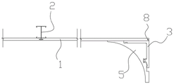
FIG. 1 is a schematic overall structure diagram of a toilet assembled arc ceiling according to an embodiment of the utility model;
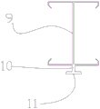
FIG. 2 is a schematic structural view of a concealed joint splicing keel of an assembled arc-shaped ceiling of a toilet according to a specific embodiment of the utility model;
FIG. 3 is a schematic structural view of an edge mounting plate of an assembled arc-shaped ceiling of a toilet according to an embodiment of the present invention;
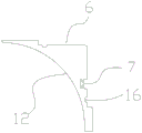
FIG. 4 is a schematic diagram of an edge molding panel for a lavatory assembled curved ceiling according to an embodiment of the present invention;
the suspended ceiling comprises a suspended ceiling main board 1, a hidden seam splicing keel 2, an edge mounting plate 3, a clamping body 4, an edge modeling plate 5, a first mounting groove 6, a clamping groove 7, a clamping groove 8, a keel main body 9, a vertical connecting plate 10, an insertion plate 11, a modeling cambered surface 12, a first mounting plate 13, a second mounting plate 14, a nailing groove 15 and a containing groove 16.
Detailed Description
In order to make the objects, technical solutions and advantages of the embodiments of the present invention clearer, the technical solutions in the embodiments of the present invention will be clearly and completely described below with reference to the drawings in the embodiments of the present invention, and it is obvious that the described embodiments are some, but not all, embodiments of the present invention. All other embodiments, which can be derived by a person skilled in the art from the embodiments given herein without making any creative effort, shall fall within the protection scope of the present invention. It should be noted that the embodiments and features of the embodiments in the present application may be arbitrarily combined with each other without conflict.
It is noted that, herein, relational terms such as first and second, and the like may be used solely to distinguish one entity or action from another entity or action without necessarily requiring or implying any actual such relationship or order between such entities or actions. Also, the terms "comprises," "comprising," or any other variation thereof, are intended to cover a non-exclusive inclusion, such that a process, method, article, or apparatus that comprises a list of elements does not include only those elements but may include other elements not expressly listed or inherent to such process, method, article, or apparatus. Without further limitation, an element defined by the phrase "comprising an …" does not exclude the presence of other identical elements in a process, method, article, or apparatus that comprises the element.
Referring to fig. 1 to 4, an assembled arc-shaped ceiling for a toilet according to an embodiment of the present invention includes a plurality of ceiling main boards 1, a plurality of blind joint studs 2 for connecting adjacent ceiling main boards 1, and edge mounting plates 3 fixedly mounted on a wall of the toilet and supported below the ceiling main boards 1; in this embodiment, a plurality of furred ceiling mainboard 1 constitutes the furred ceiling set board that is equivalent with bathroom top surface size with the help of blind joint concatenation fossil fragments 2, then on the wall is fixed with the help of the installation of limit portion mounting panel 3 to realize the installation of bathroom furred ceiling. In addition, still additionally install a detachable limit portion mo (u) lding board 5 on limit portion mounting panel 3, make the furred ceiling set board form arc molding structure in wall body position department, further become bathroom arc molding furred ceiling structure.
As one of the preferred options of this embodiment, the blind-seam splicing keel 2 comprises a keel main body 9 with an i-shaped structure, a vertical connecting plate 10 extending vertically and downwardly from a bottom plate of the keel main body 9, and an inserting plate 11 integrally connected with the lower end edge of the vertical connecting plate 10 and horizontally arranged; wherein the upper end of erecting connecting plate 10 is along the central line position department of a body coupling at the bottom plate of fossil fragments main part 9, the lower extreme of erecting connecting plate 10 is along a body coupling at the central line position department of plugboard 11 for blind joint concatenation fossil fragments 2 are whole to be symmetrical structure, and then make blind joint concatenation fossil fragments 2 when connecting two furred ceiling mainboard 1 simultaneously, and the stress intensity of blind joint concatenation fossil fragments 2 both sides is unanimous, in order to keep blind joint concatenation fossil fragments 2 atress balanced, avoid its long-term atress uneven deformation of coming out.
In addition, a card insertion groove 8 is correspondingly formed in the thin side wall surface of the suspended ceiling main board 1, when the suspended ceiling main board 1 is connected with the blind seam splicing keel 2, the insertion board 11 is inserted into the card insertion groove 8, and meanwhile, the distance from the insertion board 11 to the bottom plate of the keel main body 9 is equal to the distance from the card insertion groove 8 to the upper end surface of the suspended ceiling main board 1; the hidden joint splicing keel 2 is transversely inserted into the card insertion groove 8 by means of the insertion plate 11 so as to hang the suspended ceiling main board 1 in the vertical direction, and the hidden joint splicing keel 2 is hung on a wall hanging structure on a wall body so that the suspended ceiling assembly plate is hung in a top space of a toilet.
Additional description: the thickness of the socket board 11 is larger than the width of the card insertion slot 8, and the size difference can be 1mm in the present embodiment, so that the socket board 11 cannot be removed from the card insertion slot 8 after being inserted into the card insertion slot 8.
As a second preferred item of this embodiment, the edge mounting plate 3 includes a first mounting plate body 13 and a second mounting plate body 14 perpendicular to the first mounting plate body 13 and disposed at the end edge of the first mounting plate body 13, the edge mounting plate 3 is a right-angled plate body structure as a whole, and the nailing grooves 15 are formed on the first mounting plate body 13 and the second mounting plate body 14. After furred ceiling assembly board is constituteed in furred ceiling mainboard 1 concatenation each other, because will control the balanced reason in concatenation gap between the furred ceiling mainboard 1, the phenomenon that has great interval sometimes can appear between the limit portion of furred ceiling assembly board and the wall body, and in this embodiment, limit portion mounting panel 3 can be with the limit portion position department of first installation plate body 13 bearing at furred ceiling assembly board, follow the nailing of below nail connection recess 15 department simultaneously and assemble board with the first installation plate body 13 of fixed connection and furred ceiling, transversely follow the nailing of nail connection recess 15 department on the second installation plate body 14 again and fix to the wall body in order to make the second installation plate body 14 simultaneously on.
The edge mounting plate 3 is mounted on the wall body and bears the weight of the suspended ceiling assembly plate, and the gap between the suspended ceiling assembly plate and the wall body is also covered.
In addition, the second mounting plate 14 is provided with a clamping body 4, and the clamping body 4 and the nail-connecting groove 15 are located on the same side. The edge molding plate 5 is provided with a first mounting groove 6, and the edge mounting plate 3 is accommodated in the first mounting groove 6, so that the edge molding plate is also of a right-angle groove structure. Joint recess 7 has been seted up to first mounting groove 6 fit in, so that the joint links to each other between limit portion mounting panel 3 and the limit portion mould board 5, and when the joint body 4 inserted in joint recess 7, limit portion mounting panel 3 buries the dress in first mounting groove 6, the plate body thickness of limit portion mounting panel 3 is less than the depth of groove of first mounting groove 6, so that limit portion mould board 5 can also with the wall body after holding limit portion mounting panel 3 with first mounting groove 6, with closely laminate between the furred ceiling mainboard 1, there is not the gap.
The edge modeling plate 5 comprises three side wall surfaces, wherein two side wall surfaces are straight surfaces, the first mounting groove 6 is arranged on the two straight side wall surfaces, the third side wall surface is set to be a modeling arc surface 12, the arc surface belongs to an inwards concave arc surface, when the edge modeling plate 5 is clamped on the edge mounting plate 3, the straight side wall surfaces are respectively attached to the ceiling main plate 1 and the wall, the modeling arc surface 12 is exposed outwards, and the modeling ceiling with the arc surface modeling is formed by matching the straight bottom of the ceiling main plate 1.
The points to be supplemented are: when the edge mounting plate 3, the ceiling main board 1 and the fixed mounting edge mounting plate 3 are nailed and fixedly connected to the wall, nails are nailed from the nailing groove 15, and the tail ends of the nails can be located in the nailing groove 15, so that a gap between the edge mounting plate 3 and the edge modeling plate 5 caused by the exposure of the nails is prevented. The first mounting groove 6 of the edge molding plate 5 may be provided with a receiving groove 16 corresponding to the position of the nail, and the receiving groove may also receive the tail end of the nail, thereby achieving the same effect
Where not mentioned above, all are applicable to the prior art.
Finally, it should be noted that: the above examples are only for illustrating the technical solutions of the present invention, and are not limited thereto. Although the present invention has been described in detail with reference to the foregoing embodiments, it will be understood by those of ordinary skill in the art that: the technical solutions described in the foregoing embodiments may still be modified, or some technical features may be equivalently replaced; and such modifications or substitutions do not depart from the spirit and scope of the corresponding technical solutions of the embodiments of the present invention.
Claims (8)
1. The utility model provides a bathroom assembled arc furred ceiling which characterized in that: the suspended ceiling comprises a plurality of suspended ceiling main boards (1), a plurality of blind joint splicing keels (2) used for connecting adjacent suspended ceiling main boards (1), and edge mounting plates (3) which are fixedly arranged on a toilet wall and supported below the suspended ceiling main boards (1); still be provided with joint body (4) on limit portion mounting panel (3), still include limit portion mould board (5) that the joint was installed on limit portion mounting panel (3), first mounting groove (6) have been seted up on limit portion mould board (5), still including seting up joint recess (7) in first mounting groove (6), limit portion mould board (5) and limit portion mounting panel (3) joint make limit portion mounting panel (3) bury dress in first mounting groove (6).
2. The assembled arc-shaped suspended ceiling of the toilet, according to claim 1, is characterized in that: a card inserting groove (8) is formed in the edge of the suspended ceiling main board (1); the hidden-seam splicing keel (2) comprises a keel main body (9), a vertical connecting plate (10) arranged at the bottom end of the keel main body (9), and an inserting plate (11) horizontally arranged at the bottom end of the vertical connecting keel; the side edges of the insertion plates (11) are respectively inserted into the plurality of card insertion grooves (8) so that the hidden seam splicing keels (2) are simultaneously connected with the plurality of suspended ceiling main boards (1).
3. The assembled arc-shaped suspended ceiling of the toilet, according to claim 1, is characterized in that: and the edge part modeling plate (5) is provided with a modeling cambered surface (12).
4. The assembled arc-shaped suspended ceiling of the toilet, according to claim 1, is characterized in that: the thickness of the edge mounting plate (3) is less than or equal to the groove depth of the first mounting groove (6).
5. The assembled arc-shaped suspended ceiling of the toilet, as set forth in claim 2, wherein: the keel main body (9) is arranged to be an I-shaped keel, the vertical connecting plate (10) extends vertically downwards from the middle position of the bottom of the keel main body (9), and the lower end of the vertical connecting plate (10) is connected to the middle line position of the plug board (11).
6. The assembled arc-shaped suspended ceiling of the toilet, according to claim 1, is characterized in that: limit portion mounting panel (3) include first mounting plate body (13) and perpendicular to first mounting plate body (13) and set up second mounting plate body (14) of edge department in one's body at first mounting plate body, just all seted up on first mounting plate body (13) and second mounting plate body (14) and nailed groove (15).
7. The assembled arc-shaped suspended ceiling of the toilet, according to claim 1, is characterized in that: and the nail fixing device also comprises a plurality of accommodating grooves (16) which are formed in the first mounting groove (6) and are used for accommodating the exposed ends of the nails.
8. The assembled arc-shaped suspended ceiling of the toilet, as set forth in claim 2, wherein: the thickness of the plugboard (11) is larger than the slot width of the card slot (8), so that the plugboard (11) can expand to be tightly pressed in the card slot (8) after being inserted into the card slot (8).
Priority Applications (1)
| Application Number | Priority Date | Filing Date | Title |
|---|---|---|---|
| CN202121440358.8U CN215888867U (en) | 2021-06-28 | 2021-06-28 | Assembled arc furred ceiling in bathroom |
Applications Claiming Priority (1)
| Application Number | Priority Date | Filing Date | Title |
|---|---|---|---|
| CN202121440358.8U CN215888867U (en) | 2021-06-28 | 2021-06-28 | Assembled arc furred ceiling in bathroom |
Publications (1)
| Publication Number | Publication Date |
|---|---|
| CN215888867U true CN215888867U (en) | 2022-02-22 |
Family
ID=80561831
Family Applications (1)
| Application Number | Title | Priority Date | Filing Date |
|---|---|---|---|
| CN202121440358.8U Active CN215888867U (en) | 2021-06-28 | 2021-06-28 | Assembled arc furred ceiling in bathroom |
Country Status (1)
| Country | Link |
|---|---|
| CN (1) | CN215888867U (en) |
-
2021
- 2021-06-28 CN CN202121440358.8U patent/CN215888867U/en active Active
Similar Documents
| Publication | Publication Date | Title |
|---|---|---|
| CN113323244A (en) | Toilet assembled arc-shaped suspended ceiling and installation method thereof | |
| CN109763596B (en) | Assembled light steel keel gypsum thistle board ceiling system and construction method thereof | |
| CN215888867U (en) | Assembled arc furred ceiling in bathroom | |
| CN112160520A (en) | Wallboard leveling and hanging system and mounting method thereof | |
| CN210685259U (en) | Assembled wall hanging plate system and keel thereof | |
| CN212926642U (en) | Connecting piece for decorative plate and assembling structure using same | |
| CN211058187U (en) | Assembling structure for decorative plate | |
| CN214302640U (en) | Decorate interior wallboard cell structure and assembled wallboard system | |
| CN113323261A (en) | Assembly type suspension rod-free suspended ceiling structure and mounting method thereof | |
| CN214614934U (en) | Integral upright frame supporting structure of drop-level ceiling | |
| CN108505669A (en) | A kind of annular ceiling system | |
| CN112554415A (en) | Buckle type ceiling closing-in structure and installation method thereof | |
| CN220167363U (en) | Modeling background wall structure with closely spliced edges | |
| CN214462188U (en) | Plug-in type falls level furred ceiling molding structure | |
| CN220301682U (en) | Background wall structure with decorative edge | |
| CN112144807A (en) | Wallboard mounting structure and mounting method thereof | |
| CN219033748U (en) | Assembled furred ceiling connection structure | |
| CN215888920U (en) | Assembled does not have jib furred ceiling structure | |
| CN218074437U (en) | Multifunctional wall surface storage frame | |
| CN215368154U (en) | Plane furred ceiling structure | |
| CN219671687U (en) | Edge collecting piece for lapping independent frame type bathroom suspended ceiling | |
| CN216380195U (en) | Assembled suspended ceiling with curtain box | |
| CN213837476U (en) | Connecting component suitable for splicing and seam remaining of single veneer | |
| CN216920947U (en) | Welt keel structure | |
| CN211775294U (en) | Internal corner structure of decorative wall |
Legal Events
| Date | Code | Title | Description |
|---|---|---|---|
| GR01 | Patent grant | ||
| GR01 | Patent grant |