CN215865976U - Layering sampling equipment for water quality monitoring - Google Patents
Layering sampling equipment for water quality monitoring Download PDFInfo
- Publication number
- CN215865976U CN215865976U CN202122412817.8U CN202122412817U CN215865976U CN 215865976 U CN215865976 U CN 215865976U CN 202122412817 U CN202122412817 U CN 202122412817U CN 215865976 U CN215865976 U CN 215865976U
- Authority
- CN
- China
- Prior art keywords
- box
- monitoring
- water quality
- quality monitoring
- position department
- Prior art date
- Legal status (The legal status is an assumption and is not a legal conclusion. Google has not performed a legal analysis and makes no representation as to the accuracy of the status listed.)
- Active
Links
- 238000012544 monitoring process Methods 0.000 title claims abstract description 65
- 238000005070 sampling Methods 0.000 title claims abstract description 55
- XLYOFNOQVPJJNP-UHFFFAOYSA-N water Substances O XLYOFNOQVPJJNP-UHFFFAOYSA-N 0.000 title claims abstract description 47
- 239000004677 Nylon Substances 0.000 claims description 4
- 239000000463 material Substances 0.000 claims description 4
- 229920001778 nylon Polymers 0.000 claims description 4
- 238000007789 sealing Methods 0.000 claims description 3
- 230000003628 erosive effect Effects 0.000 abstract description 3
- 230000000694 effects Effects 0.000 description 4
- QVGXLLKOCUKJST-UHFFFAOYSA-N atomic oxygen Chemical compound [O] QVGXLLKOCUKJST-UHFFFAOYSA-N 0.000 description 3
- 239000001301 oxygen Substances 0.000 description 3
- 229910052760 oxygen Inorganic materials 0.000 description 3
- 239000003344 environmental pollutant Substances 0.000 description 2
- 238000000034 method Methods 0.000 description 2
- JMANVNJQNLATNU-UHFFFAOYSA-N oxalonitrile Chemical compound N#CC#N JMANVNJQNLATNU-UHFFFAOYSA-N 0.000 description 2
- 231100000719 pollutant Toxicity 0.000 description 2
- VYZAMTAEIAYCRO-UHFFFAOYSA-N Chromium Chemical compound [Cr] VYZAMTAEIAYCRO-UHFFFAOYSA-N 0.000 description 1
- ISWSIDIOOBJBQZ-UHFFFAOYSA-N Phenol Chemical compound OC1=CC=CC=C1 ISWSIDIOOBJBQZ-UHFFFAOYSA-N 0.000 description 1
- 230000004075 alteration Effects 0.000 description 1
- 229910052785 arsenic Inorganic materials 0.000 description 1
- RQNWIZPPADIBDY-UHFFFAOYSA-N arsenic atom Chemical compound [As] RQNWIZPPADIBDY-UHFFFAOYSA-N 0.000 description 1
- 230000009286 beneficial effect Effects 0.000 description 1
- 229910052793 cadmium Inorganic materials 0.000 description 1
- BDOSMKKIYDKNTQ-UHFFFAOYSA-N cadmium atom Chemical compound [Cd] BDOSMKKIYDKNTQ-UHFFFAOYSA-N 0.000 description 1
- 229910052804 chromium Inorganic materials 0.000 description 1
- 239000011651 chromium Substances 0.000 description 1
- 238000005260 corrosion Methods 0.000 description 1
- 230000007797 corrosion Effects 0.000 description 1
- 238000010586 diagram Methods 0.000 description 1
- 239000008187 granular material Substances 0.000 description 1
- 239000012535 impurity Substances 0.000 description 1
- JEIPFZHSYJVQDO-UHFFFAOYSA-N iron(III) oxide Inorganic materials O=[Fe]O[Fe]=O JEIPFZHSYJVQDO-UHFFFAOYSA-N 0.000 description 1
- QSHDDOUJBYECFT-UHFFFAOYSA-N mercury Chemical compound [Hg] QSHDDOUJBYECFT-UHFFFAOYSA-N 0.000 description 1
- 229910052753 mercury Inorganic materials 0.000 description 1
- 238000012986 modification Methods 0.000 description 1
- 230000004048 modification Effects 0.000 description 1
- 239000008239 natural water Substances 0.000 description 1
- 239000000575 pesticide Substances 0.000 description 1
- 231100000614 poison Toxicity 0.000 description 1
- 230000002035 prolonged effect Effects 0.000 description 1
- 239000000126 substance Substances 0.000 description 1
- 238000006467 substitution reaction Methods 0.000 description 1
- 239000003440 toxic substance Substances 0.000 description 1
Images


Landscapes
- Sampling And Sample Adjustment (AREA)
Abstract
The utility model discloses layered sampling equipment for water quality monitoring, which comprises a base, a box body and a monitoring box, wherein a slide rod is arranged in the middle position of one side of the top end of the base, the box body is arranged in the position of the top end of the slide rod, connecting buckles A are arranged at four angular positions of the top end of the box body, the outer surface of each connecting buckle A is connected with a connecting buckle B through an elastic rope, the connecting buckles B are connected to the four angular positions of the bottom end of the monitoring box, fixed columns are arranged at the four angular positions of the bottom end of the base, and an inflatable bag is arranged on the outer surface of the monitoring box close to the bottom end. The utility model solves the problems that the existing device adopts fixed water quality sampling points, cannot perform layered sampling on river water in a river channel, has poor monitoring accuracy due to the fact that river water monitoring data is one-sided, is easy to corrode under the erosion of the river water for a long time and has poor service life, and improves the monitoring accuracy and the service life of the device.
Description
Technical Field
The utility model relates to the technical field of water quality monitoring, in particular to stratified sampling equipment for water quality monitoring.
Background
The water quality monitoring is a process for monitoring and measuring the types of pollutants in the water body, the concentrations and the variation trends of various pollutants and evaluating the water quality condition. The monitoring range is very wide, and the monitoring range comprises uncontaminated and contaminated natural water (rivers, lakes, seas and underground water), various industrial drainage and the like. The main monitoring projects can be divided into two main categories: one is a comprehensive index reflecting the water quality conditions, such as temperature, chroma, turbidity, pH value, conductivity, suspended matters, dissolved oxygen, chemical oxygen demand, biochemical oxygen demand and the like; the other is some toxic substances, such as phenol, cyanogen, arsenic, lead, chromium, cadmium, mercury, organic pesticides and the like. In order to objectively evaluate the water quality of rivers and oceans, in addition to the above monitoring items, the flow velocity and flow rate are sometimes measured, and sampling equipment is used for water quality monitoring.
Present sampling equipment, water quality sampling point adopt fixed setting more, can't carry out the layering sample to river in the river course, and river monitoring data one-sidedly, the monitoring precision is not good, and sampling device is easy corrosion under the river erosion for a long time, and life is not good, for this reason, we provide a water quality monitoring and use layering sampling equipment.
SUMMERY OF THE UTILITY MODEL
The utility model aims to provide layered sampling equipment for water quality monitoring, which has the advantage of layered sampling and solves the problems that the existing device cannot perform layered sampling on river water in a river channel due to the fact that a water quality sampling point is fixedly arranged, the monitoring accuracy is poor due to the fact that river water monitoring data is one-sided, and a sampling device is easy to corrode and has a short service life due to the fact that the sampling device is corroded by the river water for a long time.
In order to achieve the purpose, the utility model provides the following technical scheme: the utility model provides a layering sampling equipment for water quality monitoring, includes base, box and monitoring box, wherein base top one side intermediate position department installs the slide bar, slide bar top position department installs the box, connector link A is all installed to four angular position departments on box top, connector link A surface is connected with connector link B through the elasticity rope, connector link B all connects in four angular position departments of monitoring bottom of the case end, the fixed column is all installed to four angular position departments of base bottom.
Preferably, an inflatable bag is arranged on the outer surface of the monitoring box close to the bottom end.
Preferably, a screw rod is installed at one side position of the sliding rod at the middle position of the box body and the base, a sliding block is sleeved at the middle position of the outer surface of the sliding rod and connected with the screw rod in a screwing mode through threads, and a motor is installed at the position, located at the top end of the screw rod, inside the box body.
Preferably, the inside one side position department of box installs the circulating pump, circulating pump bottom intermediate position department installs the sampling pipe, circulating pump top intermediate position department passes through the connecting pipe and connects in the monitoring box.
Preferably, the tail end of the sampling pipe is connected to the middle position of one side of the sliding block through a fixing buckle, and a filter is installed at the tail end of the sampling pipe.
Preferably, the screw rod, the sliding rod and the sliding block are all made of nylon materials.
Preferably, the box is internally provided with sealing rings at the positions of the gaps among the screw rod, the connecting pipe and the sampling pipe.
Compared with the prior art, the utility model has the following beneficial effects:
1. the utility model achieves the effect of layered sampling by arranging the screw rod, the sliding block, the sliding rod and the motor, the screw rod is arranged at the position of one side of the sliding rod at the middle position of the box body and the base, the sliding block is sleeved at the middle position of the outer surface of the screw rod and the outer surface of the sliding rod, the screw rod and the sliding block are connected in a screwing mode through threads, and the motor is arranged at the position, located at the top end of the screw rod, of the box body, so that the problems that layered sampling of river water in a river channel cannot be carried out due to the fact that water quality sampling points are fixedly arranged, the river water monitoring data is one-sided, and the monitoring accuracy is poor are solved, and the monitoring accuracy of the utility model is improved.
2. The screw rod, the sliding rod and the sliding block are all made of nylon materials, so that the effect of prolonging the service life of the sampling device is achieved, the problems that the sampling device is easy to rust under the erosion of river water for a long time and the service life is poor are solved, and the service life of the sampling device is prolonged.
3. According to the utility model, the effect of driving the monitoring box to float and increasing the applicability of the monitoring box is achieved by arranging the inflatable bag, the spring rope, the connecting buckle A and the connecting buckle B, the connecting buckle A is arranged at four angular positions at the top end of the box body, the connecting buckle B is arranged on the outer surface of the connecting buckle A through the elastic rope, and the connecting buckle B is connected to the four angular positions at the bottom end of the monitoring box, so that the problem that the use of the monitoring box is influenced when the monitoring box is fixedly installed and river water rises is solved, and the applicability of the monitoring box is improved.
Drawings
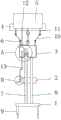
FIG. 1 is a schematic front view of the present invention;
FIG. 2 is a schematic cross-sectional view of the present invention;
FIG. 3 is an enlarged view of A in FIG. 2;
fig. 4 is an enlarged structural diagram of B in fig. 2.
In the figure: 1. a base; 2. a slider; 3. a box body; 4. an air-filled bag; 5. a monitoring box; 6. a connecting buckle A; 7. a screw rod; 8. a slide bar; 9. fixing a column; 10. an elastic cord; 11. a connecting buckle B; 12. a connecting pipe; 13. a sampling tube; 14. a seal ring; 15. a motor; 16. a circulation pump; 17. a fixing buckle; 18. and (3) a filter.
Detailed Description
The technical solutions in the embodiments of the present invention will be clearly and completely described below with reference to the drawings in the embodiments of the present invention, and it is obvious that the described embodiments are only a part of the embodiments of the present invention, and not all of the embodiments. All other embodiments, which can be derived by a person skilled in the art from the embodiments given herein without making any creative effort, shall fall within the protection scope of the present invention.
Referring to fig. 1 and 3, the technical solution of the stratified sampling apparatus for water quality monitoring provided by the present invention is: the utility model provides a layering sampling equipment for water quality monitoring, including base 1, box 3 and monitoring case 5, 1 top one side intermediate position department of base installs slide bar 8, 8 top positions of slide bar department install box 3, connector link A6 is all installed in four angular position departments on 3 tops of box, connector link A6 surface is connected with connector link B11 through elasticity rope 10, connector link B11 all connects in four angular position departments in monitoring case 5 bottoms, fixed column 9 is all installed in four angular position departments in 1 bottom of base.
The outer surface of the monitoring box 5 is provided with an inflatable bag 4 near the bottom end for floating the monitoring box 5.
Referring to fig. 2 and 3, the technical solution of the stratified sampling apparatus for water quality monitoring provided by the present invention is: the utility model provides a layering sampling equipment for water quality monitoring, includes base 1, box 3 and monitoring case 5, and box 3 and 1 intermediate position department slide bar 8 one side position department of base install lead screw 7, and lead screw 7 has cup jointed slider 2 with 8 surface intermediate position departments of slide bar, and lead screw 7 closes with slider 2 through the screw thread soon and is connected, and 3 inside lead screw 7 top positions departments that are located of box install motor 15.
The screw rod 7, the slide rod 8 and the slide block 2 are all made of nylon materials, so that the screw rod 7, the slide rod 8 and the slide block 2 are prevented from being rusted, and the service life of the utility model is prevented from being influenced.
The rest is the same as in example 1.
Referring to fig. 2 and 4, the technical solution of the stratified sampling apparatus for water quality monitoring provided by the present invention is: the utility model provides a layering sampling equipment for water quality monitoring, includes base 1, box 3 and monitoring box 5, and 3 inside one side position departments of box install circulating pump 16, and 16 bottom intermediate positions departments of circulating pump install sampling pipe 13, and 16 top intermediate positions departments of circulating pump pass through connecting pipe 12 and connect in monitoring box 5.
The rest is the same as in example 1.
The working principle is as follows: after the river channel water sampler is installed, the river channel water sampler is fixed in a river channel through the fixing columns 9, when layered sampling is needed, the motor 15 is started, the screw rod 7 is driven to rotate through the motor 15, the slide block 2 is driven to move through the screw rod 7, the tail end of the sampling pipe 13 is moved to a river channel sampling position, the circulating pump 16 is started again, river water in the river channel is pumped away through the circulating pump 16 and the sampling pipe 13 and is conveyed to the monitoring box 5 through the connecting pipe 12, and the river water is monitored through the monitoring box 5, so that the working process of the river channel water sampler is completed.
Although embodiments of the present invention have been shown and described, it will be appreciated by those skilled in the art that changes, modifications, substitutions and alterations can be made in these embodiments without departing from the principles and spirit of the utility model, the scope of which is defined in the appended claims and their equivalents.
Claims (7)
1. The utility model provides a stratified sampling equipment for water quality monitoring, includes base (1), box (3) and monitoring case (5), its characterized in that: base (1) top one side intermediate position department installs slide bar (8), slide bar (8) top position department installs box (3), four angular position departments in box (3) top all install connector link A (6), connector link A (6) surface is connected with connector link B (11) through elasticity rope (10), connector link B (11) all are connected in four angular position departments in monitoring case (5) bottom, fixed column (9) are all installed to four angular position departments in base (1) bottom.
2. The stratified sampling device for water quality monitoring according to claim 1, characterized in that: and an inflatable bag (4) is arranged on the outer surface of the monitoring box (5) close to the bottom end.
3. The stratified sampling device for water quality monitoring according to claim 1, characterized in that: the lead screw (7) is installed in box (3) and base (1) intermediate position department slide bar (8) one side position department, slider (2) have been cup jointed in lead screw (7) and slide bar (8) surface intermediate position department, lead screw (7) close with slider (2) soon through the screw thread and are connected, motor (15) are installed in box (3) inside lead screw (7) top position department that is located.
4. The stratified sampling device for water quality monitoring according to claim 1, characterized in that: the sampling box is characterized in that a circulating pump (16) is installed at one side of the inside of the box body (3), a sampling pipe (13) is installed at the middle position of the bottom end of the circulating pump (16), and the middle position of the top end of the circulating pump (16) is connected to the monitoring box (5) through a connecting pipe (12).
5. The stratified sampling device for water quality monitoring as claimed in claim 4, wherein: sampling pipe (13) end is connected in slider (2) one side intermediate position department through fixed knot (17), filter (18) are installed to sampling pipe (13) end position department.
6. The stratified sampling device for water quality monitoring as claimed in claim 3, wherein: the screw rod (7), the sliding rod (8) and the sliding block (2) are all made of nylon materials.
7. The stratified sampling device for water quality monitoring according to claim 1, characterized in that: and sealing rings (14) are arranged at the gap positions of the screw rod (7), the connecting pipe (12) and the sampling pipe (13) in the box body (3).
Priority Applications (1)
| Application Number | Priority Date | Filing Date | Title |
|---|---|---|---|
| CN202122412817.8U CN215865976U (en) | 2021-10-08 | 2021-10-08 | Layering sampling equipment for water quality monitoring |
Applications Claiming Priority (1)
| Application Number | Priority Date | Filing Date | Title |
|---|---|---|---|
| CN202122412817.8U CN215865976U (en) | 2021-10-08 | 2021-10-08 | Layering sampling equipment for water quality monitoring |
Publications (1)
| Publication Number | Publication Date |
|---|---|
| CN215865976U true CN215865976U (en) | 2022-02-18 |
Family
ID=80260519
Family Applications (1)
| Application Number | Title | Priority Date | Filing Date |
|---|---|---|---|
| CN202122412817.8U Active CN215865976U (en) | 2021-10-08 | 2021-10-08 | Layering sampling equipment for water quality monitoring |
Country Status (1)
| Country | Link |
|---|---|
| CN (1) | CN215865976U (en) |
Cited By (1)
| Publication number | Priority date | Publication date | Assignee | Title |
|---|---|---|---|---|
| CN117949516A (en) * | 2024-03-22 | 2024-04-30 | 山西天和盛环境检测股份有限公司 | Water body detection device |
-
2021
- 2021-10-08 CN CN202122412817.8U patent/CN215865976U/en active Active
Cited By (1)
| Publication number | Priority date | Publication date | Assignee | Title |
|---|---|---|---|---|
| CN117949516A (en) * | 2024-03-22 | 2024-04-30 | 山西天和盛环境检测股份有限公司 | Water body detection device |
Similar Documents
| Publication | Publication Date | Title |
|---|---|---|
| CN108692978A (en) | A kind of water body detection sampling apparatus | |
| CN106556598B (en) | Automatic in-situ nutritive salt analysis device for seawater monitoring | |
| CN212844495U (en) | Novel unmanned aerial vehicle water sampling device | |
| CN215492665U (en) | Ammonia nitrogen water quality automatic monitoring device | |
| CN215865976U (en) | Layering sampling equipment for water quality monitoring | |
| CN210742247U (en) | Offshore water quality environment monitoring device | |
| CN215263444U (en) | Anti unrestrained effectual sewage water quality monitoring device | |
| CN115078676A (en) | Water environment current situation monitoring system based on Internet of things and monitoring method thereof | |
| CN108680401B (en) | Water quality monitoring system based on unmanned ship | |
| CN110596031A (en) | A device for quantitative analysis of ammonia nitrogen in seawater | |
| CN203630124U (en) | Intelligent building water quality multi-parameter monitoring system | |
| CN108254367B (en) | Automatic detection and early warning device and method for ship-borne or shore-based water nutrient salt | |
| CN215375358U (en) | Floating water quality monitoring device | |
| CN222272289U (en) | Water quality monitoring buoy | |
| CN210487439U (en) | Water quality monitoring preliminary treatment sample thief | |
| JP2001318057A (en) | Residual chlorine measuring method and its device | |
| CN214408216U (en) | Water resource water quality testing sampling equipment | |
| CN213482213U (en) | Online monitored control system of quality of water | |
| CN211374209U (en) | Movable sampling device for lake water quality detection | |
| CN214889806U (en) | Online water quality monitoring system mounting structure | |
| CN209215360U (en) | A kind of paralic environment water monitoring device | |
| CN212844530U (en) | Water sample sampler for environmental monitoring | |
| CN111307793B (en) | An instrument and detection method for in-situ detection of deep-sea dissolved manganese | |
| CN211141560U (en) | Water sample pretreatment water tank of automatic environmental water quality monitoring station | |
| CN215894587U (en) | River course water quality testing device |
Legal Events
| Date | Code | Title | Description |
|---|---|---|---|
| GR01 | Patent grant | ||
| GR01 | Patent grant |