Pipe connecting structure with anti-falling blades
Technical Field
The utility model relates to the field of pipes, in particular to a pipe connecting structure with anti-falling blades.
Background
The corrugated pipe has the advantages of good pressure resistance, low construction cost, light weight, quick and convenient construction and the like, and is widely applied to the field of drainage. For convenient transportation, the length of each section of corrugated pipe cannot be too long, and the sections of corrugated pipe are transported to a construction site and then connected. The connection mode of the existing corrugated pipe is generally plug-in type or flange connection type. The plug-in type connection mode is as follows: and installing a rubber sealing ring at the second wave trough of the socket section, coating a lubricant, and then directly inserting the socket, wherein the socket needs to be in the reverse water flow direction and the socket section needs to be in the water flow direction. Only through sealing washer sealing connection, when meetting geology and sink the phenomenon such as, take place axial displacement easily between the sealing connection position of tubular product and tubular product. The flange connection mode requires more connecting parts such as flanges and bolt assemblies, and the operation of workers is very troublesome, and the construction cost is high.
SUMMERY OF THE UTILITY MODEL
The utility model aims to: overcome above shortcoming and provide a take tubular product connection structure of anti-drop blade, this structure is connected the first socket section and the second socket section of two tubular products through the tubulose connector, and carry out sealed anticreep through two sets of sealing washers and anti-drop blade and connect, not only the integral connection easy operation is quick, the cost is cheap, and can prevent effectively that the sealing washer from driving the relative tubulose connector axial of tubular product and kick-backing, sealed effect has been guaranteed, even later stage geology subsides also can not throw off, long service life. In addition, the anti-dropping blades are directly arranged on the inner wall of the tubular connector, so that the structure is greatly simplified, and the production and manufacturing cost is reduced.
The utility model is realized by the following technical scheme: the utility model provides a take tubular product connection structure of anti-drop blade which characterized in that: the connecting pipe comprises at least two pipes, wherein a tubular first socket section is fixedly connected to one end port of one pipe, and a tubular second socket section is also fixedly connected to one end port of the other pipe;
the pipe connecting structure with the anti-falling blades further comprises a tubular connector which can be sleeved on the peripheries of the first socket section and the second socket section and is used for connecting the first socket section and the second socket section, the inner hollow hole of the tubular connector extends to the openings at two axial ends, the middle position of the hole wall of the inner hollow hole of the tubular connector is also provided with a limiting inner flange which protrudes towards the direction close to the central axis of the inner hollow hole of the tubular connector, the inner cavity of the tubular connector forms a first matching groove from the axial end port to the position of the limiting inner flange, the inner cavity of the tubular connector forms a second matching groove from the other axial port to the position of the limiting inner flange, the first socket section and the second socket section are respectively matched and inserted into the first matching groove and the second matching groove, the axial outer end walls of the first socket section and the second socket section are respectively pressed against the two axial end walls of the limiting inner flange;
sealing rings and anti-drop blades which are sequentially arranged along the axial direction are arranged between the outer peripheral wall of the first socket section and the inner peripheral wall of the first matching groove and between the outer peripheral wall of the second socket section and the inner peripheral wall of the second matching groove, and the anti-drop blades are used for preventing the first socket section from dropping out along the axial direction relative to the first matching groove or the second socket section relative to the second matching groove;
the outer peripheral walls of the first socket section and the second socket section are respectively provided with a sealing ring groove which is arranged around the outer peripheral wall and used for installing a sealing ring and an anti-falling clamping groove used for clamping an anti-falling blade, the sealing ring groove is positioned at the position close to the outer port of the first socket section or the second socket section, and the anti-falling clamping groove is positioned at the position far away from the outer port of the first socket section or the second socket section;
the sealing rings are arranged in the corresponding sealing ring grooves in a tight fit manner, the outer peripheral parts of the sealing rings are exposed out of the sealing ring grooves, and the outer peripheral parts of the sealing rings are connected to the inner peripheral walls of the first matching grooves or the second matching grooves in a tight fit manner;
the fixed in-process that sets up on the internal perisporium in first cooperation groove or second cooperation groove of anticreep blade and from fixed connection position and extend to the direction of keeping away from first cooperation groove or the outer port of second cooperation groove gradually to the direction slope that is close to the tubulose connector the central axis and the joint is in the anticreep joint recess of the first socket section or the second socket section that correspond, and the quantity of the anticreep blade that each side of tubulose connector axial set up is a plurality of and sets up along the circumferencial direction interval distribution of the same axial position of the internal perisporium of its place tubulose connector.
In order to facilitate production and manufacture, the anti-dropping blades and the tubular connector are integrally injection-molded.
In order to facilitate the use and the installation, first socket section and second socket section are the wave crest and the wave trough bellows that set up in proper order in turn, sealing washer recess and anticreep joint recess are one of them wave trough of bellows and constitute.
Compared with the prior art, the utility model has the beneficial effects that:
1. the utility model provides a pipe connecting structure with anti-falling blades, which is characterized in that a first socket section and a second socket section of two pipes are connected through a tubular connector, and sealed anti-falling connection is carried out through two groups of sealing rings and the anti-falling blades. In addition, the anti-dropping blades are directly arranged on the inner wall of the tubular connector, so that the structure is greatly simplified, and the production and manufacturing cost is reduced.
2. According to the pipe connecting structure with the anti-falling blades, the anti-falling blades are fixedly arranged in the tubular connector and can be integrally injection-molded with the tubular connector, production and manufacturing are convenient, parts are fewer, and installation is convenient.
3. According to the pipe connecting structure with the anti-falling blades, the first socket section and the second socket section are corrugated pipes, the sealing ring groove and the anti-falling clamping groove are formed by one wave trough in the corrugated pipes, independent machining of the grooves is not needed, and production and manufacturing are convenient.
Drawings
FIG. 1 is an exploded view of an embodiment of the present invention;
FIG. 2 is a schematic diagram of the internal structure of the embodiment of the present invention;
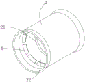
fig. 3 is a schematic structural diagram of a tubular connector according to an embodiment of the present invention.
Description of reference numerals: 1-pipe, 11-first socket section, 12-second socket section, 13-sealing ring groove, 14-anti-falling clamping groove, 2-tubular connector, 21-annular inner flange, 22-first matching groove, 23-second matching groove, 3-sealing ring and 4-anti-falling blade.
Detailed Description
The utility model is described in detail below with reference to the following description of the drawings:
as shown in fig. 1-3, a pipe connecting structure with anti-drop blades is characterized in that: the pipe fitting comprises at least two pipes 1, wherein a tubular first socket section 11 is fixedly connected to one end port of one pipe 1, and a tubular second socket section 12 is also fixedly connected to one end port of the other pipe 1;
the pipe connecting structure with the anti-falling blades further comprises a tubular connector 2 which can be sleeved on the peripheries of the first socket section 11 and the second socket section 12 and is used for connecting the first socket section and the second socket section, the inner hollow hole of the tubular connector 2 extends to the openings at two axial ends, the middle position of the hole wall of the inner hollow hole of the tubular connector 2 is also provided with a limiting inner flange 21 which protrudes towards the direction close to the central axis of the inner hollow hole, the inner cavity of the tubular connector 2 forms a first matching groove 22 from the axial end port to the position of the limiting inner flange 21, the inner cavity of the tubular connector 2 forms a second matching groove 23 from the other axial port to the position of the limiting inner flange 21, the first socket section 11 and the second socket section 12 are respectively inserted and connected in the first matching groove 22 and the second matching groove 23, the axial outer end walls of the first socket section 11 and the second socket section 12 are respectively pressed against the two axial end walls of the limiting inner flange 21;
sealing rings 3 and anti-dropping blades 4 which are sequentially arranged along the axial direction are arranged between the outer peripheral wall of the first socket section 11 and the inner peripheral wall of the first matching groove 22 and between the outer peripheral wall of the second socket section 12 and the inner peripheral wall of the second matching groove 23, and the anti-dropping blades 4 are used for preventing the first socket section 11 from dropping out along the axial direction relative to the first matching groove 22 or the second socket section 12 relative to the second matching groove 23;
the outer peripheral walls of the first socket section 11 and the second socket section 12 are respectively provided with a sealing ring groove 13 which is arranged around the outer peripheral wall and used for installing a sealing ring 3 and an anti-falling clamping groove 14 used for clamping an anti-falling blade 4, the sealing ring groove 13 is positioned at an outer port close to the first socket section 11 or the second socket section 12, and the anti-falling clamping groove 14 is positioned at an outer port far away from the first socket section 11 or the second socket section 12;
the seal rings 3 are tightly installed in the corresponding seal ring grooves 13 in a matching mode, the outer peripheral parts of the seal rings are exposed out of the seal ring grooves 13, and the outer peripheral parts of the seal rings are tightly connected to the inner peripheral walls of the first matching grooves 22 or the second matching grooves 23 in a matching mode;
the fixed in-process that sets up first cooperation groove 22 or the interior perisporium of second cooperation groove 23 on and from fixed connection position and extend to the direction of keeping away from first cooperation groove 22 or the outer port of second cooperation groove 23 gradually inclines and the joint is in the anticreep joint recess 14 of the first socket section 11 or the second socket section 12 that corresponds to the direction that is close to tubular connector 2 the central axis, the quantity of the anticreep blade 4 that tubular connector 2 axial every side set up is a plurality of and sets up along the circumferencial direction interval distribution of its place tubular connector 2's the same axial position of interior perisporium.
In order to facilitate production and manufacture, the anti-dropping blades 4 and the tubular connector 2 are integrally formed by injection molding.
In order to facilitate use and installation, the first socket section 11 and the second socket section 12 are corrugated pipes with wave crests and wave troughs alternately arranged in sequence, and the sealing ring groove 13 and the anti-falling clamping groove 14 are formed by one wave trough of the corrugated pipes.
While the utility model has been illustrated and described with respect to specific embodiments and alternatives thereof, it will be understood that various changes and modifications can be made without departing from the spirit and scope of the utility model. It is understood, therefore, that the utility model is not to be in any way limited except by the appended claims and their equivalents.