CN215845233U - Continuous blanking die for production of beam limiting clamp - Google Patents
Continuous blanking die for production of beam limiting clamp Download PDFInfo
- Publication number
- CN215845233U CN215845233U CN202121932404.6U CN202121932404U CN215845233U CN 215845233 U CN215845233 U CN 215845233U CN 202121932404 U CN202121932404 U CN 202121932404U CN 215845233 U CN215845233 U CN 215845233U
- Authority
- CN
- China
- Prior art keywords
- die
- blanking
- module
- hole
- blanking hole
- Prior art date
- Legal status (The legal status is an assumption and is not a legal conclusion. Google has not performed a legal analysis and makes no representation as to the accuracy of the status listed.)
- Active
Links
Images


Abstract
The utility model discloses a continuous blanking die for production of a limiting clamp, which integrates multiple functions of blanking, forming, punching, trimming, stamping number, texture and the like on one die, realizes a continuous blanking production mode, reduces the die testing time and improves the production efficiency. The key points of the technical scheme are as follows: a continuous blanking die for production of a limiting clamp comprises a die base body, and a blanking module, a forming module, a punching module, an embossing module and a trimming module which are integrated on the die base body, wherein the forming module comprises a first female die, a second female die, a third female die and a forming male die which are different in shape, the first female die, the second female die and the third female die are sequentially arranged at intervals, and the forming male die is formed by outwards protruding the surface of the die base body; the punching module comprises a plurality of blanking hole groups distinguished according to the hole diameter, and each blanking hole group comprises at least one blanking hole.
Description
Technical Field
The utility model relates to the technical field of blanking dies, in particular to a continuous blanking die for production of a beam limiting clamp.
Background
Some products or parts need to be produced by adopting a blanking mode, such as a limiting clamp, the limiting clamp is used for reasonably collecting and fixing a finished line in a bundling operation in an automobile, the line in the automobile is ordered and safe, when the limiting clamp is produced and manufactured on the existing production line, a plurality of dies are often adopted to be matched with the production mode, such as the processes of material forming, punching and the like need to be carried out by adopting independent dies, the production processes of the products are more, the die testing time is long, the production efficiency is low, and the production cost is higher.
Therefore, a mold capable of integrating multiple mold functions is designed, so that the production connection and the rapidity become problems to be solved in the field.
SUMMERY OF THE UTILITY MODEL
The utility model aims to solve the problems in the prior art, and provides a continuous blanking die for production of a limiting clamp, which integrates multiple functions of blanking, forming, punching, trimming, stamping, numbering, texture and the like on one die, realizes a continuous blanking production mode, reduces the die testing time and improves the production efficiency.
In order to achieve the purpose, the utility model adopts the following technical scheme:
a continuous blanking die for production of a limiting clamp comprises a die base body, and a blanking module, a forming module, a punching module, an embossing module and a trimming module which are integrated on the die base body, wherein the forming module comprises a first female die, a second female die, a third female die and a forming male die which are different in shape, the first female die, the second female die and the third female die are sequentially arranged at intervals, and the forming male die is formed by outwards protruding the surface of the die base body; the punching module comprises a plurality of blanking hole groups distinguished according to the hole diameter, and each blanking hole group comprises at least one blanking hole.
Preferably, the first concave die is composed of an arc concave surface a and a slope a, the second concave die is composed of an arc concave surface b, an arc concave surface c and a slope b, and the third concave die is composed of an arc concave surface d, a slope c and a slope d; the first female die is equipped with a first male die, the second female die is equipped with a second male die, and the third female die is equipped with a third male die.
Preferably, the arc angle of the arc concave surface a is 180 degrees, and the arc concave surface a is positioned at the bottom of the first female die and is in smooth transition connection with the slope a; the arc angle between the arc concave surface b and the arc concave surface c is 120 degrees, the arc concave surface b is positioned at the bottom of the second female die and is sequentially in smooth transition connection with the arc concave surface c and the slope b; the arc angle of the arc-shaped concave surface d is 180 degrees, the two ends of the arc-shaped concave surface d are respectively connected with the slope c and the slope d, and the inclination angle of the slope c is larger than that of the slope d.
Preferably, the trimming module is composed of a rectangular through hole and a circular through hole, and the end part of the rectangular through hole penetrates through the circular through hole.
Preferably, the number of the blanking hole groups is two in total, and the first blanking hole group and the second blanking hole group are respectively provided, the first blanking hole group comprises three first blanking holes, the second blanking hole group comprises three second blanking holes, and the aperture of the second blanking hole is larger than that of the first blanking hole.
Preferably, the punching module further comprises at least one third blanking hole, the diameter of the third blanking hole is larger than that of the second blanking hole, the second blanking hole and/or the third blanking hole are/is provided with a detachable cylindrical auxiliary die, and the cylindrical auxiliary die is provided with a central blanking hole.
Preferably, the diameter of the third blanking hole is not less than twice the diameter of the second blanking hole, the third blanking hole is provided with a cylindrical auxiliary die, and the end of the cylindrical auxiliary die corresponding to the third blanking hole is provided with a punching texture.
Preferably, the steel seal printing module, the blanking module, the forming male die, the first female die, the second female die, the third female die and the trimming module are sequentially arranged from one side of the die matrix to the other side of the die matrix.
Preferably, the three first blanking holes are distributed on two sides of the blanking module in a number relation of 2:1, the three first blanking holes are distributed in a triangular shape, the three second blanking holes are arranged at equal intervals, and the axes of the three second blanking holes are located on the same vertical plane.
Compared with the prior art, the continuous blanking die for the production of the beam limiting clamp adopting the technical scheme has the following beneficial effects:
the blanking of raw materials, the shaping of work piece, punch a hole, cut edge and multiple functions such as punching press serial number, punching press texture are integrated on a mould to realize the blanking production mode of serialization, need not to change the mould frequently, can reduce the examination mould time, improve production efficiency greatly.
Secondly, a plurality of female dies/male dies with different shapes are integrated in the forming module, so that punch forming of various shapes can be realized on one die; the punching module is integrated with a plurality of blanking holes with different apertures, so that the punching with various apertures can be realized on one die, the cost is saved, and the production efficiency is improved.
The detachable cylindrical auxiliary die can be used for punching a hole in a larger aperture when the cylindrical auxiliary die is detached, the cylindrical auxiliary die can be further installed for punching surface textures of workpieces, a central punching hole of the cylindrical auxiliary die can be further used for punching a hole in a smaller aperture, and the detachable cylindrical auxiliary die is more flexible and convenient to use.
Drawings
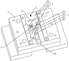
Fig. 1 is a schematic structural view of an embodiment of a continuous blanking die for manufacturing a restraining clamp according to the utility model.
Fig. 2 is a top view of the present embodiment.
Fig. 3 is a sectional view of the first female die in this embodiment.
Fig. 4 is a sectional view of the second female die in this embodiment.
Fig. 5 is a sectional view of a third concave die in this embodiment.
Reference numerals: 1. a mold base; 2. a blanking module; 3. forming a module; 30. a first female die; 300. an arc concave surface a; 301. a slope a; 31. a second female die; 310. an arc concave surface b; 311. an arc concave surface c; 312. A slope b; 32. a third female die; 320. an arc-shaped concave surface d; 321. a slope c; 322. a slope d; 33. forming a male die; 34. a first male die; 35. a second male die; 36. a third male die; 4. a punching module; 40. a first blanking hole; 41. a second blanking hole; 42. third blanking holes; 5. printing a steel seal module; 6. a trimming module; 7. and (5) a cylindrical auxiliary die.
Detailed Description
The utility model is further described below with reference to the accompanying drawings.
The continuous blanking die for the production of the restraint clip as shown in fig. 1 to 5 comprises a die base body 1, and a blanking module 2, a forming module 3, a punching module 4, a steel stamping module 5 and a trimming module 6 which are integrated on the die base body 1.
The blanking module 2 is a rectangular hole penetrating through the upper side and the lower side of the mold base body 1, the forming module 3 comprises a first female mold 30, a second female mold 31, a third female mold 32 and a forming male mold 33 which are different in shape, the first female mold 30, the second female mold 31 and the third female mold 32 are sequentially arranged at intervals, and the forming male mold 33 is formed by outwards protruding the surface of the mold base body 1.
The first concave die 30 is composed of an arc concave surface a300 and a slope a301, the second concave die 31 is composed of an arc concave surface b310, an arc concave surface c311 and a slope b312, and the third concave die 32 is composed of an arc concave surface d320, a slope c321 and a slope d 322; the first female die 30 is equipped with a first male die 34, the second female die 31 is equipped with a second male die 35, and the third female die 32 is equipped with a third male die 36.
The arc angle of the arc concave surface a300 is 180 degrees, and the arc concave surface a300 is positioned at the bottom of the first female die 30 and is in smooth transition connection with the slope a 301; the arc angle of the arc concave surface b310 and the arc concave surface c311 is 120 degrees, the arc concave surface b310 is positioned at the bottom of the second concave die 31 and is sequentially in smooth transition connection with the arc concave surface c311 and the slope b 312; the arc angle of the arc concave surface d320 is 180 degrees, the two ends of the arc concave surface d320 are respectively connected with the slope c321 and the slope d322, and the inclination angle of the slope c321 is larger than that of the slope d 322.
The punching module 4 comprises two punching hole groups distinguished according to the aperture, the number of the punching hole groups is two in total, the punching hole groups are respectively a first punching hole 40 group and a second punching hole 41 group, the first punching hole 40 group comprises three first punching holes 40, the second punching hole 41 group comprises three second punching holes 41, the aperture of the second punching hole 41 is larger than that of the first punching hole 40, the punching module 4 further comprises a third punching hole 42, the aperture of the third punching hole 42 is twice that of the second punching hole 41, the third punching hole 42 is provided with a detachable cylindrical auxiliary die 7, the cylindrical auxiliary die 7 is provided with a central punching hole, and the end part of the cylindrical auxiliary die 7 is provided with punching textures.
The three first blanking holes 40 are distributed on two sides of the blanking module 2 in a number relation of 2:1, the three first blanking holes 40 are distributed in a triangular shape, the three second blanking holes 41 are arranged at equal intervals, and the axes of the three second blanking holes are located on the same vertical plane.
The trimming module 6 is composed of a rectangular through hole and a circular through hole, the end part of the rectangular through hole penetrates through the circular through hole, and the steel seal punching module 5, the blanking module 2, the forming male die 33, the first female die 30, the second female die 31, the third female die 32 and the trimming module 6 are sequentially arranged from one side to the other side of the die base body 1.
The foregoing is a preferred embodiment of the present invention, and it will be apparent to those skilled in the art that various changes and modifications may be made without departing from the spirit of the utility model, and these should be considered to be within the scope of the utility model.
Claims (9)
1. The utility model provides a continuous blanking mould for restricting press from both sides production which characterized in that: the stamping die comprises a die base body (1), and a blanking module (2), a forming module (3), a punching module (4), a steel seal stamping module (5) and an edge cutting module (6) which are integrated on the die base body (1), wherein the forming module (3) comprises a first female die (30), a second female die (31), a third female die (32) and a forming male die (33) which are different in shape, the first female die (30), the second female die (31) and the third female die (32) are sequentially arranged at intervals, and the forming male die (33) is formed by outwards protruding the surface of the die base body (1); the punching module (4) comprises a plurality of blanking hole groups distinguished by the aperture, each blanking hole group comprising at least one blanking hole.
2. Continuous blanking die for the production of restraint clips according to claim 1, characterized in that: the first concave die (30) is composed of an arc concave surface a (300) and a slope a (301), the second concave die (31) is composed of an arc concave surface b (310), an arc concave surface c (311) and a slope b (312), and the third concave die (32) is composed of an arc concave surface d (320), a slope c (321) and a slope d (322); the first female die (30) is equipped with a first male die (34), the second female die (31) is equipped with a second male die (35), and the third female die (32) is equipped with a third male die (36).
3. The continuous blanking die for the production of a restraining clip according to claim 2, characterized in that: the arc angle of the arc concave surface a (300) is 180 degrees, and the arc concave surface a (300) is positioned at the bottom of the first female die (30) and is in smooth transition connection with the slope a (301); the arc angle between the arc concave surface b (310) and the arc concave surface c (311) is 120 degrees, the arc concave surface b (310) is positioned at the bottom of the second female die (31) and is sequentially in smooth transition connection with the arc concave surface c (311) and the slope b (312); the arc angle of the arc-shaped concave surface d (320) is 180 degrees, the two ends of the arc-shaped concave surface d (320) are respectively connected with the slope c (321) and the slope d (322), and the inclination angle of the slope c (321) is larger than that of the slope d (322).
4. Continuous blanking die for the production of restraint clips according to claim 1, characterized in that: the trimming module (6) is composed of a rectangular through hole and a circular through hole, and the end part of the rectangular through hole penetrates through the circular through hole.
5. Continuous blanking die for the production of restraint clips according to claim 1, characterized in that: the number of blanking hole groups is two in total, and is first blanking hole (40) group and second blanking hole (41) group respectively, and first blanking hole (40) group is including three first blanking hole (40), and second blanking hole (41) group is including three second blanking hole (41), the aperture of second blanking hole (41) is greater than first blanking hole (40).
6. Continuous blanking die for the production of restraint clips according to claim 5, characterized in that: the punching module (4) further comprises at least one third blanking hole (42), the diameter of the third blanking hole (42) is larger than that of the second blanking hole (41), the second blanking hole (41) and/or the third blanking hole (42) are/is provided with a detachable cylindrical auxiliary die (7), and the cylindrical auxiliary die (7) is provided with a central blanking hole.
7. Continuous blanking die for the production of restraint clips according to claim 6, characterized in that: the aperture of the third blanking hole (42) is not less than twice of the aperture of the second blanking hole (41), the third blanking hole (42) is provided with a cylindrical auxiliary die (7), and the end part of the cylindrical auxiliary die (7) corresponding to the third blanking hole (42) is provided with stamping grains.
8. Continuous blanking die for the production of restraint clips according to claim 5, characterized in that: the steel seal stamping die comprises a steel seal stamping module (5), a blanking module (2), a forming male die (33), a first female die (30), a second female die (31), a third female die (32) and an edge cutting module (6) which are sequentially arranged from one side to the other side of a die base body (1).
9. The continuous blanking die for the production of a restraining clip according to claim 8, characterized in that: the three first blanking holes (40) are distributed on two sides of the blanking module (2) in a number relation of 2:1, the three first blanking holes (40) are distributed in a triangular mode, the three second blanking holes (41) are arranged at equal intervals, and the axes of the three second blanking holes are located on the same vertical plane.
Priority Applications (1)
| Application Number | Priority Date | Filing Date | Title |
|---|---|---|---|
| CN202121932404.6U CN215845233U (en) | 2021-08-17 | 2021-08-17 | Continuous blanking die for production of beam limiting clamp |
Applications Claiming Priority (1)
| Application Number | Priority Date | Filing Date | Title |
|---|---|---|---|
| CN202121932404.6U CN215845233U (en) | 2021-08-17 | 2021-08-17 | Continuous blanking die for production of beam limiting clamp |
Publications (1)
| Publication Number | Publication Date |
|---|---|
| CN215845233U true CN215845233U (en) | 2022-02-18 |
Family
ID=80240067
Family Applications (1)
| Application Number | Title | Priority Date | Filing Date |
|---|---|---|---|
| CN202121932404.6U Active CN215845233U (en) | 2021-08-17 | 2021-08-17 | Continuous blanking die for production of beam limiting clamp |
Country Status (1)
| Country | Link |
|---|---|
| CN (1) | CN215845233U (en) |
-
2021
- 2021-08-17 CN CN202121932404.6U patent/CN215845233U/en active Active
Similar Documents
| Publication | Publication Date | Title |
|---|---|---|
| CN210547331U (en) | Multi-punch stamping structure, punch press and stamping system | |
| CN215845233U (en) | Continuous blanking die for production of beam limiting clamp | |
| CN209935629U (en) | Stamping device for automobile parts suitable for different size processing | |
| CN210412030U (en) | Bending die | |
| CN109513796A (en) | Escutcheon drawing work of shifting gears and mold | |
| CN107755536B (en) | Supporting plate forming die and method for processing supporting plate by using same | |
| CN114082840A (en) | Antenna support forming die and forming process thereof | |
| CN211707901U (en) | Combined type material pressing plate | |
| CN208247510U (en) | A kind of embossing punching die for box shell of travelling | |
| CN219443102U (en) | Stamping forming device | |
| CN216989502U (en) | Continuous forming die of automobile pipe clamp fixing support assembly | |
| CN220920655U (en) | Aviation spare part forming die | |
| CN218134436U (en) | Blank punching die for sheet metal part of front end bracket of automobile | |
| CN216989523U (en) | Novel punch and stamping die with same | |
| CN213591546U (en) | Male die with front face and back face mutually used | |
| CN214719939U (en) | Pressure plate groove adjusting base plate | |
| CN212792683U (en) | Automobile spare and accessory part multistation stamping die | |
| CN213728861U (en) | Stamping die of many processes unification | |
| CN214814010U (en) | Fine blanking die | |
| CN211386526U (en) | Be suitable for processing to have aperture blanking die of negative angle punching face | |
| CN215396419U (en) | Detachable tool for rubber air bag forming | |
| CN210614748U (en) | Baffle turn-ups trompil mould | |
| CN210333975U (en) | Continuous die for manufacturing connecting piece | |
| CN218946153U (en) | Distributed positioning type stamping forming structure | |
| CN212121349U (en) | Die set |
Legal Events
| Date | Code | Title | Description |
|---|---|---|---|
| GR01 | Patent grant | ||
| GR01 | Patent grant |