CN215844081U - Sand and stone screening device for dust fall type road and bridge engineering construction - Google Patents
Sand and stone screening device for dust fall type road and bridge engineering construction Download PDFInfo
- Publication number
- CN215844081U CN215844081U CN202023321315.6U CN202023321315U CN215844081U CN 215844081 U CN215844081 U CN 215844081U CN 202023321315 U CN202023321315 U CN 202023321315U CN 215844081 U CN215844081 U CN 215844081U
- Authority
- CN
- China
- Prior art keywords
- branch
- screening
- sand
- box
- sieve box
- Prior art date
- Legal status (The legal status is an assumption and is not a legal conclusion. Google has not performed a legal analysis and makes no representation as to the accuracy of the status listed.)
- Active
Links
Images


Abstract
The utility model relates to the technical field of wind driven generator components, in particular to a sand and stone screening device for dust-fall type road and bridge engineering construction, and solves the problems that in the prior art, the sand and stone screening device is single in function and causes dust pollution. The utility model provides a sand and stone screening plant is used in construction of dust fall type road and bridge engineering, including quick-witted case and cylinder, the inside of machine case is rotated through the bracing piece and is connected with a plurality of sieve box, all sieve boxes evenly distributed in vertical direction, the circular feed inlet has been seted up to the top center department of sieve box, the bottom of sieve box is provided with the collecting hopper, the collecting hopper passes the inside that the feed inlet extended to the sieve box with quick-witted case fixed connection and bottom discharging pipe, the both sides of sieve box all are provided with first branch, the one end that first branch is close to the sieve box is passed through the bearing housing and is rotated and be connected with the sliding sleeve. The utility model can effectively reduce the raised dust generated in the working process of the sand and stone screening device and can accelerate the processing efficiency through multi-stage screening.
Description
Technical Field
The utility model relates to the technical field of wind driven generator components, in particular to a sand and stone screening device for dust-settling road and bridge engineering construction.
Background
In road and bridge engineering work progress, often use the grit, because the particle size of grit is uneven when the grit is bought, and the particle size is very different, according to the construction demand of difference, need sieve the processing to former sand soil, at this moment sieve the grit through the building sieve, but the sieve commonly used on the building site, it is fairly simple, generally can only carry out the filtration of a grit, can't carry out multistage screening, speed is too slow, efficiency is influenced, and traditional screening plant often adopts the discharge gate of semi-open formula for the convenient ejection of compact, easily cause the raise dust pollution, to above problem, can propose a novel grit screening plant, improve screening efficiency, improve the processing environment.
SUMMERY OF THE UTILITY MODEL
The utility model aims to provide a sand and stone screening device for dust-fall type road and bridge engineering construction, and solves the problems that in the prior art, the sand and stone screening device is single in function and causes dust pollution.
In order to achieve the purpose, the utility model adopts the following technical scheme:
a sand and stone screening device for dust fall type road and bridge engineering construction comprises a machine case and an air cylinder, wherein the inside of the machine case is rotatably connected with a plurality of screen boxes through supporting rods, all the screen boxes are uniformly distributed in the vertical direction, a circular feed inlet is formed in the center of the top of each screen box, a material collecting hopper is arranged at the bottom of each screen box, the material collecting hopper is fixedly connected with the machine case, a discharging pipe at the bottom of each screen box penetrates through the feed inlet and extends to the inside of each screen box, first supporting rods are arranged on two sides of each screen box, one ends of the first supporting rods, which are close to the screen boxes, are rotatably connected with sliding sleeves through bearing sleeves, sliding chutes matched with the sliding sleeves are formed in the outer walls of the screen boxes, all the first supporting rods, which are positioned on the same side, are fixedly connected with the first supporting rods on the same side through second supporting rods, the second supporting rods are vertically arranged, the top ends and the bottom ends of the two second supporting rods are fixedly connected through third supporting rods, and the two third supporting rods are respectively fixedly connected with the two second supporting rods, one side that third branch is close to the sieve box is provided with two cylinders, the flexible end and the third branch fixed connection of cylinder and two cylinders all with quick-witted case fixed connection, the top of quick-witted case is provided with the feeder hopper, the discharging pipe of feeder hopper runs through quick-witted case and the inside that the feed inlet extended to bottom sieve box, the discharging pipe bottom that is located one of bottommost in all collecting hoppers runs through quick-witted case and extends to quick-witted outside of the case, the bottom fixedly connected with a plurality of quick-witted case is the support foot seat that the rectangular array distributes.
Preferably, one side that the bracing piece is close to the sieve box is provided with the mount pad, and the mount pad passes through the bearing housing to be connected with the bracing piece rotation, offers on the outer wall of sieve box with mount pad matched with mounting groove, sieve box passes through the cooperation realization demountable installation of mount pad and mounting groove.
Preferably, the bottom of the sieve box is of a net structure, meshes of the sieve box are sequentially increased from bottom to top, and the sieve box part is located inside the bottom aggregate bin.
Preferably, the two cylinders are arranged in an oblique line.
Preferably, the top of the pair of the feed hopper is provided with a flexible dustproof curtain in an annular structure, the inner side of the dustproof curtain is fixedly connected with an elastic ring and the outer side of the dustproof curtain is fixedly connected with a mounting ring, and the mounting ring and the feed hopper are connected in a screwed mode through threads.
The utility model has at least the following beneficial effects:
1. through the cooperation of quick-witted case, sieve box, collecting hopper, cylinder and a plurality of connecting elements, can realize the regular swing of a plurality of sieve boxes at quick-witted incasement to realize the effect of multistage screening, effectively improved screening efficiency.
2. Through realizing the demountable installation of sieve box and quick-witted case and add dustproof curtain for the screening process can be gone on by quick-witted incasement portion, takes out the sieve box after the screening is accomplished and collects the finished product, has effectively reduced the raise dust, has improved construction environment
Drawings
In order to more clearly illustrate the technical solutions of the embodiments of the present invention, the drawings needed to be used in the description of the embodiments are briefly introduced below, and it is obvious that the drawings in the following description are some embodiments of the present invention, and it is obvious for those skilled in the art to obtain other drawings based on these drawings without creative efforts.
FIG. 1 is a front cross-sectional view of the present invention;
FIG. 2 is a sectional view of the sieve box in cooperation with the hopper;
FIG. 3 is a schematic top view of the screen box connection;
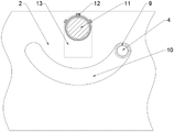
FIG. 4 is a schematic view of a chute and a mounting groove;
FIG. 5 is a schematic view of the dust curtain, mounting ring and elastic ring.
In the figure: 1. a chassis; 2. a screen box; 3. a collection hopper; 4. a first support bar; 5. a second support bar; 6. a cylinder; 7. a feed hopper; 8. a feed inlet; 9. a sliding sleeve; 10. a chute; 11. a support bar; 12. a mounting seat; 13. mounting grooves; 14. a third support bar; 15. a mounting ring; 16. a dust curtain; 17. an elastic ring.
Detailed Description
In order to make the objects, technical solutions and advantages of the present invention more apparent, the present invention is described in further detail below with reference to the accompanying drawings and embodiments. It should be understood that the specific embodiments described herein are merely illustrative of the utility model and are not intended to limit the utility model.
Referring to fig. 1-5, a sand and stone screening device for dust fall type road and bridge engineering construction comprises a machine case 1 and an air cylinder 6, wherein the inside of the machine case 1 is rotatably connected with a plurality of screen boxes 2 through a support rod 11, all the screen boxes 2 are uniformly distributed in the vertical direction, a circular feed port 8 is arranged at the center of the top of each screen box 2, a collecting hopper 3 is arranged at the bottom of each screen box 2, the collecting hopper 3 is fixedly connected with the machine case 1, a discharge pipe at the bottom of each collecting hopper penetrates through the feed port 8 and extends into the inside of each screen box 2, first support rods 4 are arranged on two sides of each screen box 2, one ends of the first support rods 4, which are close to the screen boxes 2, are rotatably connected with sliding sleeves 9 through bearing sleeves, sliding grooves 10 matched with the sliding sleeves 9 are arranged on the outer walls of the screen boxes 2, all the first support rods 4, which are positioned on the same side, are fixedly connected through second support rods 5, and are vertically arranged and fixedly connected with the first support rods 4 on the same side, the top and the bottom of two second branches 5 all are through third branch 14 fixed connection, two third branch 14 equally divide do not with two second branch 5 fixed connection, one side that third branch 14 is close to sieve box 2 is provided with two cylinders 6, the flexible end of cylinder 6 all with quick-witted case 1 fixed connection with three branch 14 fixed connection and two cylinders 6, the top of quick-witted case 1 is provided with feeder hopper 7, the discharging pipe of feeder hopper 7 runs through quick-witted case 1 and the inside that feed inlet 8 extended to bottom sieve box 2, the discharging pipe bottom that is located one of bottommost in all collection hopper 3 runs through quick-witted case 1 and extends to quick-witted case 1 outside, the bottom fixedly connected with a plurality of quick-witted case 1 is the support foot stool that the rectangular array distributes.
The scheme has the following working processes:
when using this screening plant, only need to drop into the raw materials from feeder hopper 7, the raw materials grit can get into the sieve box 2 of highest level, open the cylinder 6 after, cylinder 6 can drive first branch 4 with the help of second branch 5 and third branch 14 and be sharp reciprocating motion, this in-process sliding sleeve 9 is through sliding the regular horizontal hunting that drives sieve box 2 in spout 10, reach the purpose of screening grit, the small-size grit of being sieved passes through collecting hopper 3 and gets into in next layer sieve box 2 and continue to screen until being carried the department quick-witted case, at this moment, can directly collect the minimum grit in quick-witted case 1's bottom, the surplus grit can open quick-witted case 1 and take out each layer sieve box 2 and pour out can.
According to the working process, the following steps are known:
this grit screening plant can once only carry out multistage screening to mixing the grit, and easy and simple to handle, has effectively improved the efficiency of screening processing, and has improved the raise dust problem in the course of working through closed screening, has improved this screening plant's practicality.
Further, one side that bracing piece 11 is close to sieve box 2 is provided with mount pad 12, and mount pad 12 rotates with bracing piece 11 through the bearing housing to be connected, has seted up on the outer wall of sieve box 2 with mount pad 12 matched with mounting groove 13, and sieve box 2 realizes demountable installation through the cooperation of mount pad 12 with mounting groove 13, and detachable sieve box 2 takes out the finished product after being convenient for seal the screening, can improve the raise dust problem and be convenient for collect the grit of selecting.
Further, the bottom of sieve box 2 is network structure and increases in proper order from supreme single sieve box 2's mesh down, and sieve box 2 parts are located the inside of bottom aggregate bin 3, can avoid the grit to leak outward from this and ensure that all grit all pass through multistage screening.
Further, two cylinders 6 are the bevel angle line setting, and the bevel angle line setting can ensure that all first branch 4 atresss evenly to make sieve box 2 can steadily swing under the effect of the even external force of both sides.
Further, feeder hopper 7 to the top be provided with the flexible dustproof curtain 16 that is the loop configuration, the inboard fixedly connected with elasticity circle 17 and the outside fixedly connected with collar 15 of dustproof curtain 16, collar 15 and feeder hopper 7 close the connection soon through the screw thread, elasticity circle 17 cooperation dustproof curtain 16 can wrap up the feed cylinder export during the use, throw material and accomplish back elasticity circle 17 and can tighten up the entry, reduce the raise dust mouth, detachable connection convenient to detach dustproof curtain 16 between collar 15 and the feeder hopper 7.
To sum up, the cooperation of each part and structure not only can realize the multi-stage screening to the grit, has improved each part stability and cooperation degree in the screening process simultaneously to further improved dustproof effect, simplified operating procedure, synthesized the practicality that has improved this grit screening plant from a plurality of aspects.
The foregoing shows and describes the general principles, essential features, and advantages of the utility model. It will be understood by those skilled in the art that the present invention is not limited to the embodiments described above, which are merely illustrative of the principles of the utility model, but that various changes and modifications may be made without departing from the spirit and scope of the utility model, which fall within the scope of the utility model as claimed. The scope of the utility model is defined by the appended claims and equivalents thereof.
Claims (5)
1. The utility model provides a sand and stone screening plant is used in construction of dust fall type road and bridge engineering, includes quick-witted case (1) and cylinder (6), its characterized in that: the screening machine is characterized in that the inside of the machine case (1) is rotatably connected with a plurality of screening boxes (2) through a support rod (11), all the screening boxes (2) are uniformly distributed in the vertical direction, a circular feed inlet (8) is formed in the center of the top of each screening box (2), a collecting hopper (3) is arranged at the bottom of each screening box (2), the collecting hopper (3) is fixedly connected with the machine case (1), a discharge pipe at the bottom of each collecting hopper penetrates through the corresponding feed inlet (8) and extends into the corresponding screening box (2), first support rods (4) are arranged on two sides of each screening box (2), one ends, close to the screening boxes (2), of the first support rods (4) are rotatably connected with sliding sleeves (9) through bearing sleeves, sliding chutes (10) matched with the sliding sleeves (9) are formed in the outer walls of the screening boxes (2), and all the first support rods (4) positioned on the same side are fixedly connected through second support rods (5), the utility model discloses a screening machine, including second branch (5) and third branch (14), second branch (5) are vertical setting and the equal fixed connection of first branch (4) with one side, two the top and the bottom of second branch (5) all are through third branch (14) fixed connection, two third branch (14) are equallyd divide respectively with two second branch (5) fixed connection, one side that third branch (14) are close to sieve box (2) is provided with two cylinders (6), the flexible end and third branch (14) fixed connection and two cylinders (6) of cylinder (6) all with quick-witted case (1) fixed connection, the top of machine case (1) is provided with feeder hopper (7), the discharging pipe of feeder hopper (7) runs through quick-witted case (1) and feed inlet (8) and extends to the inside of bottom sieve box (2), all the bottom that is located the bottommost among collection hopper (3) discharging pipe runs through quick-witted case (1) and extends to quick-witted case (1) outside, the bottom of the case (1) is fixedly connected with a plurality of supporting foot seats distributed in a rectangular array.
2. The sand and stone screening device for dust-settling road and bridge engineering construction of claim 1, wherein: one side that bracing piece (11) are close to sieve box (2) is provided with mount pad (12), mount pad (12) are rotated with bracing piece (11) through the bearing housing and are connected, set up on the outer wall of sieve box (2) with mount pad (12) matched with mounting groove (13), sieve box (2) realize demountable installation through the cooperation of mount pad (12) with mounting groove (13).
3. The sand and stone screening device for dust fall type road and bridge engineering construction according to claim 2, characterized in that the bottom of the screen box (2) is of a net structure, meshes of the single screen box (2) are sequentially enlarged from bottom to top, and the screen box (2) is partially positioned in the bottom aggregate bin (3).
4. The sand and stone screening device for dust-settling road and bridge engineering construction of claim 1, wherein: the two cylinders (6) are arranged in an oblique angle line.
5. The sand and stone screening device for dust-settling road and bridge engineering construction of claim 1, wherein: the top of the pair of feeder hopper (7) is provided with flexible dustproof curtain (16) that is the loop configuration, the inboard fixedly connected with elasticity circle (17) and the outside fixedly connected with collar (15) of dustproof curtain (16), collar (15) and feeder hopper (7) close the connection soon through the screw thread.
Priority Applications (1)
| Application Number | Priority Date | Filing Date | Title |
|---|---|---|---|
| CN202023321315.6U CN215844081U (en) | 2020-12-31 | 2020-12-31 | Sand and stone screening device for dust fall type road and bridge engineering construction |
Applications Claiming Priority (1)
| Application Number | Priority Date | Filing Date | Title |
|---|---|---|---|
| CN202023321315.6U CN215844081U (en) | 2020-12-31 | 2020-12-31 | Sand and stone screening device for dust fall type road and bridge engineering construction |
Publications (1)
| Publication Number | Publication Date |
|---|---|
| CN215844081U true CN215844081U (en) | 2022-02-18 |
Family
ID=80237569
Family Applications (1)
| Application Number | Title | Priority Date | Filing Date |
|---|---|---|---|
| CN202023321315.6U Active CN215844081U (en) | 2020-12-31 | 2020-12-31 | Sand and stone screening device for dust fall type road and bridge engineering construction |
Country Status (1)
| Country | Link |
|---|---|
| CN (1) | CN215844081U (en) |
Cited By (1)
| Publication number | Priority date | Publication date | Assignee | Title |
|---|---|---|---|---|
| CN115193871A (en) * | 2022-07-15 | 2022-10-18 | 山东海林环保设备工程有限公司 | Multi-source coal-based solid waste multi-stage dehydration screening device |
-
2020
- 2020-12-31 CN CN202023321315.6U patent/CN215844081U/en active Active
Cited By (2)
| Publication number | Priority date | Publication date | Assignee | Title |
|---|---|---|---|---|
| CN115193871A (en) * | 2022-07-15 | 2022-10-18 | 山东海林环保设备工程有限公司 | Multi-source coal-based solid waste multi-stage dehydration screening device |
| CN115193871B (en) * | 2022-07-15 | 2024-04-19 | 山东海林环保设备工程有限公司 | Multi-source coal-based solid waste multistage dehydration screening device |
Similar Documents
| Publication | Publication Date | Title |
|---|---|---|
| CN208191207U (en) | A kind of seed size category filter device | |
| CN209549926U (en) | The dedicated sand of civil building dries classified screening device | |
| CN108787459A (en) | A kind of Sand screen of automatic collection stone for building | |
| CN208912484U (en) | A kind of mineralized waste vibrating screening machine | |
| CN215844081U (en) | Sand and stone screening device for dust fall type road and bridge engineering construction | |
| CN208600121U (en) | A kind of more granularity sand screening plants for building | |
| CN107837998A (en) | A kind of fine sand screening plant for being automatically drained out rough sand | |
| CN208695550U (en) | A kind of screening plant preparing premixing mortar | |
| CN207271397U (en) | Crushing material lapping device | |
| CN207138245U (en) | A kind of modified chemical industry just expects screening machine | |
| CN211306915U (en) | Aggregate transition bin with double discharge ports | |
| CN208879068U (en) | A kind of architectural engineering small vibrating sand sieving machine | |
| CN210253019U (en) | Rotary screen for superfine potassium sulfate | |
| CN208975956U (en) | A kind of mixed feed screening plant | |
| CN209403080U (en) | A kind of corn cell thresing machine | |
| CN208198870U (en) | A kind of quartz automatic charging device | |
| CN207519136U (en) | A kind of efficient agricultural fertilizer device | |
| CN216323325U (en) | Material screening device for injection molding equipment | |
| CN206168754U (en) | A sieving mechanism that is used for rice to process except that particle rice | |
| CN212524837U (en) | Sand screening machine for hydraulic engineering | |
| CN210701063U (en) | Novel building screening sand device | |
| CN209476662U (en) | A kind of product inspection sieve of high-efficiency feed | |
| CN203105251U (en) | Integrated production and equipment of plant seedling raising and cultivation media | |
| CN208449831U (en) | Sand sieving machine | |
| CN208032684U (en) | A kind of soil crushes and screens all-in-one machine |
Legal Events
| Date | Code | Title | Description |
|---|---|---|---|
| GR01 | Patent grant | ||
| GR01 | Patent grant |