CN215838852U - Base station and cleaning robot system - Google Patents
Base station and cleaning robot system Download PDFInfo
- Publication number
- CN215838852U CN215838852U CN202121975624.7U CN202121975624U CN215838852U CN 215838852 U CN215838852 U CN 215838852U CN 202121975624 U CN202121975624 U CN 202121975624U CN 215838852 U CN215838852 U CN 215838852U
- Authority
- CN
- China
- Prior art keywords
- cleaning
- base station
- track
- groove
- assembly
- Prior art date
- Legal status (The legal status is an assumption and is not a legal conclusion. Google has not performed a legal analysis and makes no representation as to the accuracy of the status listed.)
- Active
Links
- 238000004140 cleaning Methods 0.000 title claims abstract description 587
- 239000010865 sewage Substances 0.000 claims abstract description 37
- 239000007788 liquid Substances 0.000 claims description 92
- 238000005406 washing Methods 0.000 claims description 27
- 239000000463 material Substances 0.000 claims description 4
- 230000002829 reductive effect Effects 0.000 abstract description 9
- 230000002035 prolonged effect Effects 0.000 abstract description 2
- 230000009286 beneficial effect Effects 0.000 description 21
- 239000012535 impurity Substances 0.000 description 18
- 230000000694 effects Effects 0.000 description 14
- 238000010586 diagram Methods 0.000 description 13
- 238000000034 method Methods 0.000 description 11
- 230000008569 process Effects 0.000 description 10
- 230000033001 locomotion Effects 0.000 description 9
- XLYOFNOQVPJJNP-UHFFFAOYSA-N water Substances O XLYOFNOQVPJJNP-UHFFFAOYSA-N 0.000 description 8
- 239000000428 dust Substances 0.000 description 7
- 230000002349 favourable effect Effects 0.000 description 6
- 230000007246 mechanism Effects 0.000 description 6
- 230000006870 function Effects 0.000 description 5
- 238000012423 maintenance Methods 0.000 description 5
- 239000007921 spray Substances 0.000 description 5
- 230000009471 action Effects 0.000 description 4
- 238000005108 dry cleaning Methods 0.000 description 4
- 230000036961 partial effect Effects 0.000 description 4
- 238000003860 storage Methods 0.000 description 4
- 230000008859 change Effects 0.000 description 3
- 230000003993 interaction Effects 0.000 description 3
- 238000010009 beating Methods 0.000 description 2
- 238000001514 detection method Methods 0.000 description 2
- 238000009434 installation Methods 0.000 description 2
- 238000004519 manufacturing process Methods 0.000 description 2
- 238000012986 modification Methods 0.000 description 2
- 230000004048 modification Effects 0.000 description 2
- 238000012544 monitoring process Methods 0.000 description 2
- 238000012545 processing Methods 0.000 description 2
- 238000005096 rolling process Methods 0.000 description 2
- 239000000725 suspension Substances 0.000 description 2
- WHXSMMKQMYFTQS-UHFFFAOYSA-N Lithium Chemical compound [Li] WHXSMMKQMYFTQS-UHFFFAOYSA-N 0.000 description 1
- 230000008901 benefit Effects 0.000 description 1
- 230000005540 biological transmission Effects 0.000 description 1
- 230000003749 cleanliness Effects 0.000 description 1
- 238000004891 communication Methods 0.000 description 1
- 230000007797 corrosion Effects 0.000 description 1
- 238000005260 corrosion Methods 0.000 description 1
- 238000013461 design Methods 0.000 description 1
- 230000009977 dual effect Effects 0.000 description 1
- 230000005611 electricity Effects 0.000 description 1
- 238000004880 explosion Methods 0.000 description 1
- 239000004744 fabric Substances 0.000 description 1
- 238000011086 high cleaning Methods 0.000 description 1
- 230000006872 improvement Effects 0.000 description 1
- 230000002452 interceptive effect Effects 0.000 description 1
- 230000000670 limiting effect Effects 0.000 description 1
- 229910052744 lithium Inorganic materials 0.000 description 1
- 230000004807 localization Effects 0.000 description 1
- 238000013507 mapping Methods 0.000 description 1
- 229910052987 metal hydride Inorganic materials 0.000 description 1
- 229910052759 nickel Inorganic materials 0.000 description 1
- PXHVJJICTQNCMI-UHFFFAOYSA-N nickel Substances [Ni] PXHVJJICTQNCMI-UHFFFAOYSA-N 0.000 description 1
- -1 nickel metal hydride Chemical class 0.000 description 1
- 238000005086 pumping Methods 0.000 description 1
- 230000002441 reversible effect Effects 0.000 description 1
- 239000007787 solid Substances 0.000 description 1
- 230000007480 spreading Effects 0.000 description 1
- 238000003892 spreading Methods 0.000 description 1
- 238000010408 sweeping Methods 0.000 description 1
- 238000009736 wetting Methods 0.000 description 1
Images


Landscapes
- Cleaning In General (AREA)
Abstract
The utility model discloses a base station and a cleaning robot system. Wherein, the base station includes: the base station comprises a base station body and a cleaning assembly; the cleaning device comprises a base station body, a cleaning assembly and a cleaning piece, wherein a rail groove with a notch arranged laterally is formed in the base station body, the cleaning assembly is configured to run along the rail groove, the cleaning assembly is provided with the cleaning piece, and the cleaning piece is used for cleaning a cleaning system of the cleaning robot through interference with the cleaning system of the cleaning robot; the inner wall surface of the rail groove located below is inclined downward toward the outside of the rail groove. Therefore, the possibility that sewage and sundries are remained in the track groove is reduced, the service life of the track groove is prolonged, and the smoothness of the cleaning assembly relative to the base station body is improved.
Description
Technical Field
The utility model relates to the technical field of smart homes, in particular to a base station and a cleaning robot system.
Background
At present, the base station can set up mobilizable washing piece usually and wash the plane mop of sweeping and dragging integrative cleaning machines people, however, in the cleaning process, have sewage or debris to remain in the track groove of washing piece operation, influence the reliability of washing piece operation.
SUMMERY OF THE UTILITY MODEL
In the summary section a series of concepts in a simplified form is introduced, which will be described in further detail in the detailed description section. This section of the utility model is not intended to define key features or essential features of the claimed subject matter, nor is it intended to be used as an aid in determining the scope of the claimed subject matter.
An embodiment of the first aspect of the present invention provides a base station for a cleaning system for washing a cleaning robot, the base station comprising: the cleaning device comprises a base station body and a cleaning assembly, wherein a rail groove with a notch arranged laterally is formed in the base station body, the cleaning assembly is configured to run along the rail groove, a cleaning piece is arranged on the cleaning assembly, and the cleaning piece is used for cleaning a cleaning system of the cleaning robot through interference with the cleaning system of the cleaning robot.
Optionally, the base station body comprises a cleaning groove located below the cleaning assembly, and the track groove is arranged on the inner wall of the cleaning groove; wherein, the inner wall surface of the track groove at the lower part inclines downwards towards the inner part of the cleaning groove.
Optionally, the number of the track grooves is two, and the two track grooves are oppositely arranged along the transverse direction of the base station body.
Optionally, a rack is disposed in the track groove, and the cleaning assembly is moved along the track groove by the rack.
Optionally, the rack is disposed on an inner wall of the track groove located above.
Optionally, the cleaning assembly includes a driving part and a bracket, the bracket is provided with a first gear linked with the driving part, and the first gear is meshed with the rack to enable the bracket to move along the track groove.
Optionally, the support is provided with a support portion, the support portion and the first gear are distributed at intervals along the extending direction of the track groove, and the support portion includes a support wheel configured to run along the track groove.
Optionally, the base station further comprises a track detachably connected with the base station body, the track is provided with a track groove and a rack, and the rack and the track are of an integrated structure.
Optionally, the wash assembly is further provided with a track cleaner.
Optionally, the track cleaning member is disposed at a side portion of the washing assembly; the track cleaning member is disposed obliquely to the outside of the wash unit.
Optionally, the cleaning tank is provided with a drain outlet, the cleaning assembly further comprises a cleaning piece arranged towards the tank bottom of the cleaning tank, and the cleaning piece is used for drawing sundries in the cleaning tank towards the drain outlet.
Optionally, the cleaning member comprises a first cleaning member and a second cleaning member arranged on the bracket; wherein the first and second wash members remove foreign materials on the cleaning system by interference with the cleaning system of the cleaning robot.
Optionally, the driving part is also in driving connection with the second cleaning part to drive the second cleaning part to rotate relative to the bracket.
Optionally, the cleaning assembly further comprises: and the cleaning liquid discharged by the liquid outlet device is used for cleaning the cleaning system and then is contained in the cleaning tank.
An embodiment of a second aspect of the present invention provides a cleaning robot system, including: a cleaning robot including a cleaning system; and the base station of any of the first aspects, the washing assembly for cleaning the cleaning system.
According to the base station and the cleaning robot system provided by the embodiment of the utility model, the track groove is formed in the base station body, and the cleaning assembly is configured to run along the track groove, so that the cleaning assembly can move along the base station body, the automatic cleaning of the cleaning system is realized, the operation of manually cleaning the cleaning system or replacing a new cleaning system is omitted, the manual operation is simplified, and the manual cleaning experience is improved. Notch side direction through the track groove sets up, and the internal face and the notch intercommunication of track groove below are located, and the outside downward sloping towards the track groove, make the washing subassembly fall into the sewage and the impurity in the track groove at clean cleaning machines people's clean system in-process, can be outside of the guide outflow track groove of the internal face that the track groove that the slope set up is located the below, it is unsmooth for the operation of base station body to have reduced sewage and debris and remain and lead to washing the subassembly in the track groove, corrode the possibility in track groove, be favorable to improving the life in track groove, and improve the smooth and easy nature and the reliability of washing the subassembly for the operation of base station body.
The foregoing description is only an overview of the technical solutions of the present application, and the present application can be implemented according to the content of the description in order to make the technical means of the present application more clearly understood, and the following detailed description of the present application is given in order to make the above and other objects, features, and advantages of the present application more clearly understandable.
Drawings
The following drawings of the utility model are included to provide a further understanding of the utility model as a part of the examples. The drawings illustrate embodiments of the utility model and, together with the description, serve to explain the principles of the utility model.
In the drawings:
FIG. 1 is a schematic structural diagram of a cleaning robot system according to an alternative embodiment of the present invention;
FIG. 2 is a schematic structural view of a cleaning robot according to an alternative embodiment of the present invention;
FIG. 3 is a schematic diagram of a perspective view of the embodiment of FIG. 2;
FIG. 4 is a schematic diagram of a partial explosion of the embodiment of FIG. 3;
fig. 5 is a schematic structural diagram of a base station according to an alternative embodiment of the present invention;
FIG. 6 is a schematic diagram illustrating a perspective view of the embodiment of FIG. 5;
FIG. 7 is a partial schematic diagram of a further perspective view of the embodiment of FIG. 6;
fig. 8 is a partial structural diagram of a base station body according to an alternative embodiment of the present invention;
FIG. 9 is an enlarged partial schematic view of the embodiment of FIG. 8 at A;
FIG. 10 is a cross-sectional view from one perspective of the embodiment shown in FIG. 8;
FIG. 11 is a schematic diagram illustrating a further perspective of the embodiment of FIG. 8;
FIG. 12 is a schematic structural diagram of a track in accordance with an alternative embodiment of the present invention;
FIG. 13 is a schematic diagram illustrating a perspective view of the embodiment of FIG. 12;
FIG. 14 is a schematic structural view of a cleaning assembly according to an alternative embodiment of the present invention;
FIG. 15 is a schematic diagram illustrating a perspective view of the embodiment of FIG. 14;
FIG. 16 is a schematic diagram illustrating a further perspective of the embodiment of FIG. 14;
FIG. 17 is a schematic structural view of a cleaning assembly according to another alternative embodiment of the present invention;
FIG. 18 is a schematic structural view of a cleaning assembly according to yet another alternative embodiment of the present invention;
FIG. 19 is a schematic diagram of a cleaning assembly according to yet another alternative embodiment of the present invention.
Description of the reference numerals
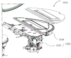
10 cleaning robot, 110 machine body, 111 forward part, 112 backward part, 120 sensing system, 121 determining device, 122 buffer, 130 control module, 140 driving system, 141 driving wheel module, 142 driven wheel, 150 cleaning system, 151 dry cleaning system, 152 side brush, 153 wet cleaning system, 1531 cleaning head, 1532 driving unit, 1533 driving platform, 1534 supporting platform, 160 energy system, 170 man-machine interaction system, 20 base station, 21 base station body, 211 sewage draining outlet, 212 cleaning groove, 22 track, 221 rack, 222 track groove, 223 first inner wall surface, 30 cleaning component, 31 first cleaning piece, 32 bracket, 33 second cleaning piece, 34 driving part, 341 first gear, 342 motor, 345 first rotating shaft, 35 liquid outlet device, 351, 36 cleaning piece, 37 supporting part, 38 track cleaning piece, 381 cleaning piece, 382 mounting part, 383 first track cleaning piece, 382 second orbital cleaning member, 40 liquid feed portion.
Detailed Description
In the following description, numerous specific details are set forth in order to provide a more thorough understanding of the present invention. It will be apparent, however, to one skilled in the art, that the present invention may be practiced without one or more of these specific details.
It should be noted that the terminology used herein is for the purpose of describing particular embodiments only and is not intended to be limiting of exemplary embodiments according to the utility model. As used herein, the singular is intended to include the plural unless the context clearly dictates otherwise. It will be further understood that the terms "comprises" and/or "comprising," when used in this specification, specify the presence of stated features, integers, steps, operations, elements, and/or components, but do not preclude the presence or addition of one or more other features, integers, steps, operations, elements, components, and/or groups thereof.
Exemplary embodiments according to the present invention will now be described in more detail with reference to the accompanying drawings. These exemplary embodiments may, however, be embodied in many different forms and should not be construed as limited to only the embodiments set forth herein. It is to be understood that these embodiments are provided so that this disclosure will be thorough and complete, and will fully convey the concept of these exemplary embodiments to those skilled in the art.
As shown in fig. 1 to 19, an embodiment of the present invention provides a base station 20 and a cleaning robot 10 system, wherein, as shown in fig. 1, the cleaning robot system includes a cleaning robot 10 and a base station 20, that is, the base station 20 is used in cooperation with the cleaning robot 10.
Further, as shown in fig. 2 and 3, the cleaning robot 10 may include a machine body 110, a sensing system 120, a control module 130, a driving system 140, a cleaning system 150, an energy system 160, and a human-machine interaction system 170. It will be appreciated that the cleaning robot 10 may be a self-moving cleaning robot or other cleaning robot that meets the requirements. A self-moving cleaning robot is an apparatus that automatically performs a cleaning operation in a certain area to be cleaned without a user's operation. Wherein when the self-moving cleaning robot starts working, the self-moving cleaning apparatus performs a cleaning task starting from the base station 20. When the self-moving cleaning robot 10 completes the cleaning task or other situations requiring suspension of the cleaning task, the self-moving cleaning robot 10 may return to the base station 20 for charging or other operations.
As shown in fig. 2, the machine body 110 includes a forward portion 111 and a rearward portion 112, and has an approximately circular shape (circular front and rear), but may have other shapes including, but not limited to, an approximately D-shape with a front and rear circle, and a rectangular or square shape with a front and rear.
As shown in fig. 2, the sensing system 120 includes a position determining device 121 disposed on the machine body 110, a collision sensor and a proximity sensor disposed on a bumper 122 of the forward portion 111 of the machine body 110, a cliff sensor disposed on a lower portion of the machine body 110, and a sensing device such as a magnetometer, an accelerometer, a gyroscope, and an odometer disposed inside the machine body 110 for providing various position information and motion state information of the machine to the control module 130. The position determining device 121 includes, but is not limited to, a camera, a Laser Distance Sensor (LDS).
As shown in fig. 2, the forward portion 111 of the machine body 110 may carry a bumper 122, the bumper 122 detects one or more events in the travel path of the cleaning robot 10 via a sensor system, such as an infrared sensor, provided thereon when the driving wheel module 141 propels the cleaning robot 10 to walk on the floor during cleaning, and the cleaning robot 10 may control the driving wheel module 141 to make the cleaning robot 10 respond to the event, such as to get away from an obstacle, by the event detected by the bumper 122, such as an obstacle, a wall.
The control module 130 is disposed on a circuit board in the machine body 110, And includes a non-transitory memory, such as a hard disk, a flash memory, And a random access memory, a communication computing processor, such as a central processing unit, And an application processor, And the application processor uses a positioning algorithm, such as a Simultaneous Localization And Mapping (SLAM), to map an environment in which the cleaning robot 10 is located according to the obstacle information fed back by the laser distance measuring device. And the distance information and speed information fed back by the sensors, cliff sensors, magnetometers, accelerometers, gyroscopes, odometers and other sensing devices arranged on the buffer 122 are combined to comprehensively judge which working state and position the cleaning robot 10 is currently in, and the current pose of the cleaning robot 10, such as passing a threshold, putting a carpet on the cliff, being blocked above or below the cleaning robot, being full of dust boxes, being taken up and the like, and specific next-step action strategies can be given according to different conditions, so that the cleaning robot 10 has better cleaning performance and user experience.
As shown in fig. 3, drive system 140 may steer machine body 110 across the ground based on drive commands having distance and angle information (e.g., x, y, and θ components). The drive system 140 includes a drive wheel module 141, and the drive wheel module 141 can control both the left and right wheels, and in order to more precisely control the motion of the machine, it is preferable that the drive wheel module 141 includes a left drive wheel module and a right drive wheel module, respectively. The left and right drive wheel modules are disposed along a transverse axis defined by the machine body 110. In order for the cleaning robot 10 to be able to move more stably or with greater mobility on the floor surface, the cleaning robot 10 may include one or more driven wheels 142, the driven wheels 142 including, but not limited to, universal wheels. The driving wheel module 141 includes a road wheel and a driving motor and a control circuit for controlling the driving motor, and the driving wheel module 141 may further be connected with a circuit for measuring a driving current and an odometer. The drive wheel may have a biased drop-type suspension system, be movably secured, such as rotatably attached to the machine body 110, and receive a spring bias that is biased downward and away from the machine body 110. The spring bias allows the drive wheels to maintain contact and traction with the floor with a certain landing force while the cleaning elements of the cleaning robot 10 also contact the floor with a certain pressure.
The human-computer interaction system 170 comprises keys on a panel of the host computer, and the keys are used for a user to select functions; the machine control system can further comprise a display screen and/or an indicator light and/or a loudspeaker, wherein the display screen, the indicator light and the loudspeaker show the current state or function selection item of the machine to a user; and a mobile phone client program can be further included. For the path navigation type automatic cleaning equipment, a map of the environment where the equipment is located and the position of a machine can be displayed to a user at a mobile phone client, and richer and more humanized function items can be provided for the user.
The cleaning system 150 may be a dry cleaning system 151 and/or a wet cleaning system 153.
As shown in fig. 3, the dry cleaning system 151 provided in the embodiment of the present invention may include a roller brush, a dust box, a blower, and an air outlet. The rolling brush with certain interference with the ground sweeps the garbage on the ground and winds the garbage to the front of a dust suction opening between the rolling brush and the dust box, and then the garbage is sucked into the dust box by air which is generated by the fan and passes through the dust box and has suction force. The dry cleaning system 151 may also include an edge brush 152 having an axis of rotation that is angled relative to the floor for moving debris into the roller brush area of the cleaning system 150.
As shown in fig. 3 and 4, a wet cleaning system 153 according to an embodiment of the present invention may include: a cleaning head 1531, a driving unit 1532, a water supply mechanism, a liquid storage tank, and the like. The cleaning head 1531 may be disposed below the liquid storage tank, and the cleaning liquid in the liquid storage tank is transferred to the cleaning head 1531 through the water delivery mechanism, so that the cleaning head 1531 performs wet cleaning on the surface to be cleaned. In other embodiments of the present invention, the cleaning liquid in the liquid storage tank can also be directly sprayed to the surface to be cleaned, and the cleaning head 1531 can clean the surface by uniformly spreading the cleaning liquid.
Among other things, the cleaning head 1531 is used to clean a surface to be cleaned, and the driving unit 1532 is used to drive the cleaning head 1531 to substantially reciprocate along a target surface, which is a part of the surface to be cleaned. The cleaning head 1531 reciprocates along the surface to be cleaned, and a cleaning cloth or a cleaning plate is disposed on a surface of the cleaning head 1531 contacting the surface to be cleaned, and generates high frequency friction with the surface to be cleaned by the reciprocating motion, thereby removing stains on the surface to be cleaned.
In the embodiment provided by the present invention, as shown in fig. 5, the base station 20 includes a base station body 21 and a cleaning assembly 30, wherein the cleaning assembly 30 is movably disposed on the base station body 21. Specifically, the wash unit 30 is movable relative to the base station body 21, for example, the wash unit 30 is capable of reciprocating in the left-right direction of the base station 20 as indicated by the solid arrow in fig. 5, and the direction indicated by the broken arrow in fig. 5 is the front-rear direction of the base station 20. The washing assembly 30 includes a washing member for removing foreign materials on the cleaning system 150 by interference with the cleaning of the cleaning robot 10 and the system 150 to accomplish the cleaning of the cleaning system 150.
Specifically, as shown in fig. 8, 9, 10 and 11, the washing assembly 30 is configured to run along the rail groove 222 by providing the rail groove 222 on the base station body 21, and it can be understood that the washing assembly 30 is configured to be capable of reciprocating along the rail groove 222, so that the washing assembly 30 can move along the base station body 21, thereby achieving automatic cleaning of the cleaning system 150 by interference of the washing assembly 30 with the cleaning system 150 of the cleaning robot 10. That is to say, cleaning robot 10 can realize self-cleaning on the washing subassembly 30 of basic station 20, and then has saved the operation of artifical clean cleaning system 150 or change new cleaning system 150, has simplified manual operation, has promoted artifical clean experience to be favorable to reducing clean cost, be suitable for popularization and application.
As shown in fig. 9, 12 and 13, the notch of the track groove 222 is laterally arranged, that is, the notch of the track groove 222 is located on the side surface of the base station body 21, an inner wall surface defining the lower side of the track groove 222 is a first inner wall surface 223, the wash water and impurities falling into the track groove 222 during cleaning of the cleaning system 150 of the cleaning robot 10, by the first inner wall surface 223 being inclined downward toward the outside of the track groove 222, will flow out of the outside of the track groove under the guidance of the first inner wall surface 223 being inclined, that is, the first inner wall surface 223 is inclined to provide a certain guiding function, so that the sewage and the impurities do not remain in the rail groove 222 for a long time to corrode or damage the rail groove 222, or the smoothness of the operation of the cleaning assembly 30 with respect to the base station body 21 is affected, thereby contributing to the improvement of the service life of the track groove 222 and the smoothness and reliability of the operation of the cleaning assembly 30 with respect to the base station body 21. Meanwhile, the inner wall surface of the lower portion of the track groove 222 is inclined downward toward the outer portion of the track groove 222, so that the track groove is convenient to process, easy to implement, simple in structure, low in cost and suitable for popularization and application.
In the above embodiment, as shown in fig. 8, 9, 10 and 11, the base station body 21 includes a cleaning tank 212 located below the cleaning assembly 30, and the cleaning tank 212 is used for accommodating the sundries removed by the cleaning assembly 30 from the cleaning system 150 of the cleaning robot 10 and/or collecting the sewage generated during the cleaning of the cleaning system 150, so as to facilitate the subsequent treatment of the sundries and the sewage and to improve the cleanliness of the environment near the base station 20. It is to be understood that the debris removed from the cleaning system 150 may include dirt, hair, debris, particulate dust, or other debris as desired, and the utility model is not limited in particular.
The rail groove 222 is arranged on the inner wall of the cleaning groove 212, so that the rail groove 222 is positioned inside the cleaning groove 212, that is, the cleaning assembly 30 can move above the cleaning groove 212 along the rail groove 222, and further, sewage and sundries in the process of cleaning the cleaning system 150 by the cleaning assembly 30 can reliably fall into the cleaning groove 212, thereby reducing the possibility of secondary pollution caused by the sewage and the sundries falling outside the cleaning groove 212 and being beneficial to improving the cleaning effect of the cleaning assembly 30.
As shown in fig. 10 and 13, the inner wall surface of the track groove 222 below is inclined downwards towards the inside of the cleaning groove 212, that is, the first inner wall surface 223 is inclined downwards towards the inside of the cleaning groove 212, so that during the cleaning process of the cleaning system 150 of the cleaning robot 10, sewage and sundries entering the track groove 222 are not easy to remain on the first inner wall surface 223, that is, the sewage and sundries can flow into the inside of the cleaning groove 212 under the guidance of the first inner wall surface 223 which is arranged obliquely, and further, the possibility that the sewage and sundries remaining in the track groove 222 cause the cleaning assembly 30 to run unsmoothly relative to the base station body 21 and corrode the track groove 222 is reduced, thereby being beneficial to improving the running smoothness and reliability of the cleaning assembly 30 relative to the base station 20 and prolonging the service life of the track 22. Meanwhile, the sundries and the sewage in the rail groove 222 flow into the cleaning groove under the guidance of the first inner wall surface 223, the possibility that the sewage and the sundries fall into the outside of the cleaning groove 212 to cause secondary pollution is reduced, and meanwhile, the sundries in the cleaning groove 212 are conveniently treated in a centralized manner, so that the treatment efficiency of the sundries is improved.
In the embodiment provided by the present invention, the number of the track grooves 222 is two, and the two track grooves 222 are oppositely disposed in the transverse direction of the base station body 21. Wherein, the transverse direction of the base station body 21 is as shown in the front-back direction in fig. 5, that is, two track grooves 222 are distributed at the front and back ends of the base station body, the extending direction of the track grooves 222 is parallel to the left-right direction of the base station body 21, and the cleaning assembly 30 runs along the two track grooves 222 to ensure the reliability and stability of the operation of the cleaning assembly 30 relative to the base station body 21. It will be appreciated that two track grooves 222 are located at either end of the cleaning assembly.
In this embodiment, as shown in fig. 9 and 11, a rack 221 is disposed in the track groove 222, and the cleaning assembly 30 runs along the track groove 222 through the rack 221, that is, the rack 221 is disposed inside the track groove 222, so that the size between the rack 221 and the track groove 222 is reduced, which is beneficial to reducing the volume of the base station body 21, and further, the requirement for disposing the base station 20 in a compact structure can be met, and the application range of the product is expanded.
Further, the rack 221 is disposed on the inner wall of the track groove 222 above, that is, the rack 221 for determining the operation direction and providing the operation power for the operation of the washing unit 30 relative to the base station body 21 is disposed on the upper wall surface of the track groove 222, and the lower wall surface of the track groove 222 disposed opposite to the upper wall surface can provide the supporting force for the operation of the washing unit 30 relative to the base station body 21, and due to the fact that the lower wall surface of the track groove 222 is a smooth wall surface compared to the rack 221, such an arrangement avoids the problem that the rack 221 is disposed on the lower wall surface of the track groove 222, so that the washing unit 30 is difficult to clean when falling on the rack 221 and affecting the operation smoothness of the washing unit 30 relative to the base station body 21 in the process of cleaning the cleaning system 150 of the cleaning robot 10.
That is, the rack 221 is disposed on the inner wall surface of the track groove 222 above the track groove 222, which is beneficial to reducing the difficulty of cleaning the track groove 222, so as to ensure that the cleaning groove 212 has high cleaning performance and improve the smoothness and reliability of the operation of the cleaning assembly 30 along the track groove 222. Meanwhile, noise generated in the operation process of the cleaning assembly 30 relative to the track groove 222 is reduced, and the use experience of a user is improved.
In an example of the present invention, as shown in fig. 12 and 13, the base station 20 further includes a rail 22 detachably connected to the base station body 21, the rail 22 is provided with a rail groove 222 and a rack 221, that is, the rack 221 for determining an operation direction and providing an operation power for the operation of the cleaning assembly 30 relative to the base station body 21 and the rail groove 222 for providing a supporting force for the operation of the cleaning assembly 30 relative to the base station body 21 are both disposed on the rail 22, which is beneficial to reducing the assembly difficulty of the base station 20, improving the production efficiency, reducing the noise generated by the operation of the cleaning assembly 30, and is suitable for popularization and application.
Further, track 22 can be dismantled with basic station body 21 and be connected for can dismantle track 22 from basic station body 21 and get off to maintain, clear up, change, and then be favorable to improving maintenance efficiency, promote the clearance and experience, and reduce and trade a cost, be suitable for popularization and application.
On one hand, the rack 221 and the rail 22 are of an integrated structure, so that the assembly operation of the rack 221 and the rail 22 is simplified, and the assembly difficulty of the rail 22 is further reduced.
On the other hand, rack 221 is split type structure with track 22, can install rack 221 in track 22's suitable position department promptly, and then be convenient for dismantle the unloading from track 22 with rack 221 and clear up and maintain rack 221, be convenient for clear up and maintain track groove 222 simultaneously, and easy operation is favorable to reducing cost of maintenance, improves clean experience.
In some possible embodiments provided by the present invention, the cleaning assembly 30 includes a driving portion 34 and a bracket 32, the bracket 32 is provided with a first gear 341 linked with the driving portion 34, and the driving portion 34 is configured to drive the first gear 341 to engage with the rack 221 so as to enable the bracket 32 to move along the track groove 222, wherein the driving portion 34 can drive the first gear 341 to move on the rack 221 in forward and backward directions, so as to drive the bracket 32 of the cleaning assembly 30 to move back and forth along the track groove 222, which is beneficial to improving the cleaning effect of the cleaning system 150 for cleaning the cleaning assembly 30.
Wherein, the driving part 34 drives the first gear 341 to move on the rack 221 in a predetermined direction by the engagement between the first gear 341 and the rack 221, and the cleaning assembly 30 moves along the track groove 222.
Specifically, as shown in fig. 14 and 15, the driving portion 34 includes a motor 342 and a first rotating shaft 345, the motor 342 is in driving connection with the first rotating shaft 345, that is, the motor 342 operates to drive the first rotating shaft 345 to rotate, the first rotating shaft 345 is disposed through the bracket 32, and first gears 341 engaged with the racks 221 are disposed at two ends of the first rotating shaft 345, so that the motor 342 drives the first rotating shaft 345 to rotate, the first gears 341 at two ends of the first rotating shaft 345 are engaged with the racks 221, and the bracket 32 is driven to move relative to the base station body 21 along the two track grooves 222, thereby cleaning the cleaning system 150 of the cleaning robot 10. Further, the motor 342 can drive the first rotating shaft 345 to rotate forward or backward, so that the bracket 32 can reciprocate along the track groove 222, thereby improving the cleaning effect of the cleaning assembly 30 on the cleaning system 150.
It can be understood that the first gear 341 and the first shaft 345 may be an integrated structure, which simplifies the assembly operation of the first gear 341 and the first shaft 345 and is beneficial to improving the production efficiency, or the first gear 341 and the first shaft 345 are a split structure, that is, the first gear 341 is detachably disposed on the first shaft 345, which facilitates the detachment of the first gear 341 from the first shaft 345 for maintenance and replacement, and is beneficial to reducing the maintenance and replacement cost. The present invention is not particularly limited with respect to the specific connection manner of the first gear 341 and the first rotation shaft 345.
In this embodiment, as shown in fig. 14 and 16, the support 32 is further provided with a support portion 37, the support portion 37 and the first gear 341 are distributed at intervals along the extending direction of the track groove 222, that is, the support portion 37 is distributed on two sides of the support 32 close to the track 22, the support portion 37 includes a support wheel arranged far from the support 32, and the support wheel is located in the track groove 222, so that the support wheel supports the cleaning assembly 30 by running along the track 22, which is beneficial to improving the running stability of the cleaning assembly 30 relative to the base station body 21, and meanwhile, the support portion 37 is arranged so that the support portion 37 and the first gear 341 simultaneously support the support 32, which is further beneficial to reducing the support force of the first gear 341, improving the service life of the first gear 341, and reducing the noise of the first gear 341 during running along the rack 221.
That is to say, in the base station 20 provided in the embodiment of the present invention, the driving portion 34 drives the first rotating shaft 345 to rotate, the first gear 341 is meshed with the rack 221 on the track 22 of the base station body 21 to drive the bracket 32 to move relative to the base station body 21, and meanwhile, the supporting wheel of the supporting portion 37 moves along the track groove 222, so that the reliability and the stability of the movement of the bracket 32 along the track groove 222 are greatly improved, and the base station is suitable for popularization and application.
In some possible embodiments provided by the present invention, as shown in fig. 14, 15 and 16, the cleaning assembly 30 further includes a rail cleaning member 38 for cleaning the rail groove 222, and as the sundries and the sewage adhere to and remain inside the rail groove 222, and corrode and damage the rail groove, and affect the smoothness of the cleaning assembly 30 running along the rail groove 222, the rail groove 222 is cleaned by the rail cleaning member 38, and the sundries and the sewage in the rail groove 222 are discharged in time, so that the possibility of the sundries and the sewage remaining and accumulating in the rail groove 222 can be reduced, and the smoothness and the reliability of the cleaning assembly 30 running in the rail groove 222 can be further improved, which is beneficial for improving the rail cleaning efficiency of the cleaning assembly 30, prolonging the service life of the rail groove 222, and improving the reliability of the base station 20.
That is, in the base station 20 according to the embodiment of the present invention, the inner wall surface of the track groove 222 located below guides the sewage and the impurities in the track groove 222 to easily flow out of the track groove 222, and the track cleaning member 38 cleans the track groove 222, so that the sewage and the impurities in the track groove 222 can quickly and completely flow out of the track groove 222, and further the cleanability of the track groove 222 is improved, that is, the present invention ensures that the track groove 222 has high cleanability through a dual structure, and further the service life of the track groove 222 is prolonged, and the operation reliability of the cleaning assembly 30 is improved.
On one hand, the rail cleaning piece 38 can be separated from the rail groove 222, for example, the rail cleaning piece 38 can be separately arranged, or detachably arranged on the cleaning assembly, when the rail groove 222 is dirty, or under the condition that sundries remain in the rail groove 222 after the base station body 21 is used for a period of time, an operator can hold the rail cleaning piece 38 to clean the rail groove 222, and remove the rail groove 222 from the rail cleaning piece 38 to store the rail cleaning piece after cleaning, so that the operation is simple and the use is convenient. It will be appreciated that the track cleaning member may be provided on other structures as desired.
On the other hand, the rail cleaning member 38 may be disposed on the cleaning assembly 30, specifically, the cleaning assembly 30 includes a support 32 running along the rail groove 222, and the rail cleaning member 38 is disposed on the support 32 of the cleaning assembly 30, that is, the rail cleaning member 38 moves along with the movement of the support 32 of the cleaning assembly 30, so that when the cleaning assembly 30 runs along the rail groove 222 to clean the cleaning system 150, the rail groove 222 is cleaned by the rail cleaning member 38, the operation of manually holding the rail cleaning member 38 to clean the rail groove 222 is simplified, the function of the cleaning assembly 30 is increased, and the cleaning assembly is suitable for popularization and application.
In the embodiment, the rail cleaning member 38 is disposed on the cleaning assembly 30 and includes the cleaning member 381 located in the rail groove 222, so that when the cleaning assembly 30 runs along the rail groove 222, the cleaning member 381 located inside the rail groove 222 of the rail cleaning member 38 also moves along the rail groove 222, so as to clean the rail groove 222, thereby preventing the occurrence of corrosion and rusting of the rail groove 222 due to the remaining of sewage or impurities in the rail groove 222 for a long time, which is beneficial to improving the service life of the rail groove 222, and simultaneously preventing the impurities and sewage from affecting the running smoothness of the cleaning assembly 30 relative to the rail groove 222, further being beneficial to improving the running smoothness and reliability of the cleaning assembly 30 relative to the rail groove 222, and being beneficial to ensuring higher cleaning efficiency of the cleaning assembly 30. It is understood that the cleaning elements 381 can be bristles, rubber blades, wiper strips or other cleaning structures as desired, and the present invention is not limited thereto.
In the above embodiment, the rail cleaning member 38 is disposed at the side portion of the cleaning assembly 30, and the end portion of the cleaning assembly 30 between the two side portions is used for movably connecting with the rail groove 222, so that during the movement of the cleaning assembly 30 relative to the rail groove 222, the rail cleaning member 38 disposed at the side portion of the cleaning assembly 30 is located in front of the end portion of the cleaning assembly 30 in the moving direction, that is, the rail cleaning member 38 can clean a portion of the rail groove 222 matching with the end portion of the cleaning assembly 30 in advance, which is beneficial to improving the smoothness and reliability of the movement of the cleaning assembly 30 along the rail groove 222.
In this embodiment, the rail cleaning member 38 is disposed obliquely to the outer side of the cleaning assembly 30, that is, the rail cleaning member 38 is disposed obliquely to the end of the rail groove 222 along the extending direction of the rail groove 222, which is beneficial to improve the thoroughness and effectiveness of the rail cleaning member 38 in cleaning the rail groove 222. If the rail cleaning member 38 is disposed on the cleaning assembly 30 perpendicular to the extending direction of the rail groove 222, that is, the rail cleaning member 38 is disposed perpendicular to the moving direction of the cleaning assembly 30, as the cleaning assembly 30 moves left and right along the rail groove 222, the rail cleaning member 38 pushes more impurities in the rail groove 222 to both ends of the rail groove 222, and the impurities cannot be removed from the rail groove 222 well. In this embodiment, the rail cleaning member 38 is disposed to be inclined toward the outer side of the cleaning assembly 30, that is, the rail cleaning member 38 is disposed to be inclined toward the end of the rail groove 222 along the extending direction of the rail groove 222, when the cleaning assembly 30 moves left and right along the rail groove 222, the rail cleaning member 38 can better clean impurities in the rail groove 222 to the outside of the rail groove 222, so as to improve the thoroughness and effectiveness of the rail cleaning member 38 in cleaning the rail groove 222, which is beneficial to prolonging the service life of the rail groove 222, and improve the smoothness and reliability of the cleaning assembly 30 moving along the rail groove 222.
In some possible embodiments provided by the present invention, since the number of the track grooves is two, the track cleaning members 38 may be distributed on any side of the bracket 32 facing the track grooves 222, and the track cleaning members 38 may also be disposed on both sides of the bracket 32 facing the track grooves 222, so that the two track grooves 222 can be cleaned by the track cleaning members 38, and the smoothness and reliability of the operation of the bracket 32 relative to the base station body 21 are further improved.
In one example of the present invention, the bracket 32 is provided with one rail cleaning member 38 at a side facing the same rail groove 222, that is, one rail groove 222 is cleaned by one rail cleaning member 38. Fig. 14 is a schematic structural view of the cleaning assembly 30 according to an embodiment of the present invention, in which the rail cleaning member 38 is inclined toward one end of the rail groove 222. In fig. 16, the rail cleaning member 38 is disposed at a position of the bracket 32 near the left end portion of the rail groove 222, and the rail cleaning member 38 is disposed obliquely toward the left end portion of the rail groove 222. In other embodiments of the present invention, if the rail cleaning member 38 is located at a position of the bracket 32 near the right end of the rail groove 222, the rail cleaning member 38 is disposed obliquely toward the right end of the rail groove 222.
When the rail cleaning member 38 is obliquely arranged at the left end of the bracket 32, and the bracket 32 drives the rail cleaning member 38 to move leftwards, the obliquely arranged rail cleaning member 38 can smoothly remove impurities in the rail groove 222.
On the other hand, as shown in fig. 17, the two rail cleaning members 38 are disposed on one side of the bracket 32 facing the same rail groove 222, that is, one rail groove 222 is cleaned by using the two rail cleaning members 38, which is beneficial to improving the cleaning efficiency and cleaning effect of the rail groove 222. Wherein the two rail cleaning members 38 include a first rail cleaning member 383 and a second rail cleaning member 384, the rail slot 222 includes a first end and a second end, the first rail cleaning member 383 is disposed obliquely toward the first end of the rail slot 222 and is located at a position of the bracket 32 near the first end, and the second rail cleaning member 384 is disposed obliquely toward the second end of the rail slot 222 and is located at a position of the bracket 32 near the second end. If the first end is the left end of the rail groove 222 and the second end is the right end of the rail groove 222, the first rail cleaning member 383 is located at a position of the bracket 32 near the left end of the rail groove 222, the second rail cleaning member 384 is located at a position of the bracket 32 near the right end of the rail groove 222, that is, the first rail cleaning member 383 is located at the left side of the second rail cleaning member 384, the first rail cleaning member 383 is inclined toward the left end of the rail groove 222, and the second rail cleaning member 384 is inclined toward the right end of the rail groove 222.
With this arrangement, the rail cleaning members 38 at both ends of the bracket 32 can better remove foreign materials from the rail 22 when the cleaning assembly 30 moves left and right along the rail groove 222. If the cleaning assembly 30 moves leftwards along the rail groove 222, under the action of the first rail cleaning member 383, the sundries and the sewage in the rail groove 222 can be drawn close to the left end portion of the rail groove 222, and the sundries and the sewage at the left end portion of the rail groove 222 can be cleaned out of the rail groove 222 due to the inclined arrangement of the first rail cleaning member 383 to the left end portion of the rail groove 222, so that the cleanness of the rail groove 222 is ensured. On the contrary, when the cleaning assembly 30 moves rightwards along the rail groove 222, the sundries and the sewage in the rail groove 222 can be drawn towards the right end portion of the rail groove 222 by the second rail cleaning member 384, and the sundries and the sewage at the right end portion of the rail groove 222 can be cleaned out of the rail groove 222 due to the inclined arrangement of the second rail cleaning member 384 towards the right end portion of the rail groove 222, so that the cleanness of the rail groove 222 is ensured.
That is, by arranging the first track cleaning member 383 and the second track cleaning member 384 on one side of the bracket 32 facing the same track groove 222, and positioning the first track cleaning member 383 and the second track cleaning member 384 at two sides of the bracket 32 and inclining towards the outside of the bracket, in the process that the cleaning assembly 30 reciprocates left and right along the track groove 222, the two track cleaning members 38 respectively clean sundries and sewage to the outside of the track groove 222 completely and reliably in the corresponding part of the track groove 222, so as to ensure that the track groove 222 has high cleanability, which is beneficial to prolonging the service life of the track groove 222, and improving the smoothness and reliability of the operation of the cleaning assembly 30 relative to the base station body 21, and is suitable for popularization and application.
It can be understood that, for the two track grooves 222, one track cleaning member 38 or two track cleaning members 38 may be respectively disposed on either side of the bracket 32 facing the two track grooves 222, for example, as shown in fig. 15, one track cleaning member 38 may be respectively disposed on both sides of the bracket 32, or, as shown in fig. 19, two track cleaning members 38 may be respectively disposed on both sides of the bracket 32, or, as shown in fig. 18, one track cleaning member 38 may be disposed on one side of the bracket 32, and two track cleaning members 38 may be disposed on the other side of the bracket 32, and the different number of the track cleaning members 38 may satisfy the requirements of different structures of the cleaning assembly 30 and different cleaning abilities of the track grooves 222, thereby expanding the application range of the product.
In some possible embodiments provided by the present invention, as shown in fig. 16, the rail cleaning member 38 includes a mounting portion 382 connected to the cleaning member 381, the mounting portion 382 is detachably connected to the cleaning assembly 30, that is, the mounting portion 382 connects the cleaning member 381 and the cleaning assembly 30, and since the cleaning member 381 is located in the rail groove 222, in the process that the cleaning assembly 30 moves along the rail groove 222, the mounting portion 382 drives the cleaning member 381 to move along the rail groove 222, so as to clean the rail groove 222, which is simple in structure and low in cost.
Can dismantle even with washing subassembly 30 through installation department 382, can dismantle the installation department 382 who is connected with cleaning member 381 from washing subassembly 30 and get off to maintain, clear up, change, easy operation is favorable to reducing maintenance, a cost of changing to promote the clean experience of track cleaning member 38. Specifically, the detachable connection may be realized by other connection structures that meet the requirements, such as a bolt threaded connection, a hook buckle, and the like, and the present invention is not particularly limited.
In some possible embodiments of the present invention, as shown in fig. 6, the cleaning tank 212 is provided with a drain outlet 211, the drain outlet 211 is located at least one side of the cleaning tank 212, and impurities and sewage in the cleaning tank 212 can be removed to the outside of the cleaning tank 212 through the drain outlet 211.
As shown in fig. 15, the cleaning assembly 30 further includes a cleaning member 36, the cleaning member 36 faces the bottom of the cleaning slot 212, the cleaning member 36 draws the impurities in the cleaning slot 212 toward the drain 211, for example, the cleaning member 36 abuts against the bottom of the cleaning slot 212, and when the cleaning assembly 30 runs along the track slot 222, the cleaning member 36 draws the impurities in the cleaning slot 212 toward the drain 211, so that the impurities can be concentrated, quickly and smoothly discharged through the drain 211, which is favorable for improving the drain efficiency and drain effect of the base station 20, and improving the satisfaction degree of the user.
It is understood that the base station 20 may further include a sewage draining mechanism, which is communicated with the sewage draining outlet 211 to convey the impurities in the cleaning tank 212 to the outside of the cleaning tank 212 through the sewage draining outlet 211 by a pumping action, etc. of the sewage draining mechanism, further improving the sewage draining effect of the base station 20. Specifically, the sewage draining mechanism may include a fan assembly or a pump body assembly, or a sewage draining assembly meeting the requirement, and the present invention is not particularly limited.
Further, the base station 20 further comprises a collecting box which is communicated with the cleaning groove 212 through a drain outlet 211, so that sundries in the cleaning groove 212 are conveyed to the collecting box through a drain mechanism, the cleaning effect of the cleaning piece is prevented from being influenced by the overflow of the sundries in the cleaning groove 212, the working environment is dirty, and the arrangement of the collecting box is beneficial to ensuring a good cleaning effect and beneficial to the centralized processing of the collected sundries.
In one example of the present invention, as shown in fig. 14 and 16, the cleaning assembly 30 further includes a first cleaning member 31 and a second cleaning member 33 disposed on the bracket 32, wherein the first cleaning member 31 and the second cleaning member 33 are different structures, and since the bracket 32 can move along the rail groove 222 disposed on the base station body 21 under the driving of the driving portion 34, the bracket 32 serves as a moving component which can drive the first cleaning member 31 and the second cleaning member 33 to move relative to the base station body 21, so that the first cleaning member 31 interferes with the cleaning system 150 of the cleaning robot 10, and the second cleaning member 33 interferes with the cleaning system 150 to remove the impurities on the cleaning system 150, that is, the cleaning robot 10 can automatically clean the cleaning assembly. It will be appreciated that after the first and second cleaning members 31 and 33 remove debris from the cleaning system 150, the debris will fall into the cleaning tank 212.
Wherein, the first cleaning member 31 includes a cleaning scraper, which interferes with the cleaning system 150 to remove the impurities on the cleaning system 150. The second wash member 33 comprises a wash roller rotatably disposed with respect to the frame 32, the wash roller interfering with the cleaning system 150 to remove debris from the cleaning system 150. Further, the outer surface of the cleaning roller is provided with brushes and/or blades, and the brushes and/or blades can go deep into the cleaning system 150 to take out the dirt stored in the cleaning system, so that the cleaning effect is further improved.
Wherein the second cleaning member 33 and the first cleaning member 31 are disposed in parallel on the bracket 32. The second cleaning members 33 may be disposed in parallel on any side of the first cleaning member 31, for example, if there are a plurality of second cleaning members 33, the second cleaning members 33 may also be disposed in parallel on any side or two sides of the first cleaning member 31, or, if there are a plurality of first cleaning members 31, the first cleaning members 31 may be disposed in parallel on any side or two sides of the second cleaning members 33.
In an example of the present invention, the second cleaning member 33 may be always in front of the first cleaning member 31 during the driving part 34 drives the bracket 32 to reciprocate along the track groove 222. With this arrangement, the second cleaning member 33 can firstly clean the portion to be cleaned of the cleaning system 150 (such as the cleaning head), that is, the bristles or blades of the second cleaning member 33 generate a beating effect on the cleaning head during the rotation of the second cleaning member 33, which causes the sundries stored in the cleaning head to be shaken out and scraped off in the vibration generated by the beating effect, and then the scraper of the first cleaning member 31 scrapes off the sundries carried out or shaken out of the cleaning head and the sewage on the cleaning head, thereby ensuring that the cleaning head can be cleaned more thoroughly.
In some possible embodiments provided by the present invention, the driving portion 34 is further connected to the second cleaning member 33 for driving the second cleaning member 33 to rotate relative to the bracket 32, that is, when the motor 342 of the driving portion 34 drives the first rotating shaft 345 to rotate, and drives the bracket 32 to move along the track groove 222, the motor 342 drives the second cleaning member 33 to rotate relative to the bracket 32. Therefore, the movement of the bracket 32 relative to the base station body 21 can be simultaneously driven by one motor 342, and the second cleaning member 33 is driven to rotate relative to the bracket 32, such as the rotation movement of the second cleaning member 33, so that the arrangement of one driving part 34 is simplified, the design requirement of compact product structure can be met, the cost is reduced, and the device is suitable for popularization and application.
In this embodiment, the driving part 34 drives the cleaning assembly 30 to move left and right along the track groove 222 and drives the second cleaning member 33 to rotate by the motor 342 in cooperation with the multi-stage gears. If the driving part 34 includes a motor 342 and a gear assembly, the motor 342 drives the bracket 32 to move through the gear assembly and simultaneously the second cleaning member 33 rotates, i.e. the driving gear assembly and the second cleaning member 33 rotate synchronously.
In this embodiment, the motor 342 can rotate in the forward and reverse directions, so that the bracket 32 can be driven to move in two opposite directions, and the second cleaning member 33 can be driven to rotate in two directions (i.e. clockwise rotation and counterclockwise rotation). For example, the motor 342 may drive the second cleaning member 33 to rotate clockwise while driving the carriage 32 to move leftward with respect to the base station body 21; the motor 342 can also drive the second cleaning member 33 to rotate counterclockwise while driving the carriage 32 to move rightward relative to the base station body 21. It should be noted that the type and size of each gear are not limited herein, and can be selected accordingly according to actual requirements.
In some possible implementation embodiments provided by the present invention, as shown in fig. 14, the cleaning assembly 30 further includes a liquid outlet device 35, during the cleaning process of the cleaning system 150 of the cleaning robot 10 by the cleaning assembly 30, the liquid outlet device 35 of the cleaning assembly 30 may work simultaneously, the liquid outlet device 35 sprays the cleaning liquid onto the cleaning system 150, the cleaning system 150 is cleaned by the impact force of the cleaning liquid, or the cleaning system 150 is soaked by the cleaning liquid, so that the cleaning effect is improved during the cleaning process of the cleaning system 150 by the cleaning member.
Further, the liquid outlet device 35 can spray the cleaning liquid on the second cleaning member 33, and since the second cleaning member 33 is in contact with the cleaning system 150 of the cleaning robot 10 by rotation, the cleaning liquid sprayed on the second cleaning member 33 by the liquid outlet device 35 can be uniformly applied to the cleaning system 150 by the rotation of the second cleaning member 33, thereby ensuring good cleaning effect. It is understood that the liquid outlet device 35 can also spray the cleaning liquid onto the cleaning system 150 and the second cleaning member 33 simultaneously, so as to further improve the wetting efficiency of the cleaning system 150.
It will be appreciated that, because the cleaning assembly 30 is positioned above the cleaning tank 212, the cleaning solution is received in the cleaning tank 212 and drained through the drain of the cleaning tank 212 after cleaning the cleaning system 150.
In the above embodiment, the liquid outlet device 35 of the base station 20 is movably disposed, for example, the liquid outlet device 35 moves along the track groove 222 along the support frame 32, so that the cleaning liquid can be more uniformly sprayed or smeared on the cleaning system 150 of the cleaning robot 10 and/or the second cleaning member 33, and the cleaning assembly 30 can improve the cleaning effect and the cleaning efficiency when cleaning the cleaning system 150 of the cleaning robot 10. It will be appreciated that in order to ensure the safety of the cleaning robot 10 and the base station 20 from electricity usage, spillage of cleaning liquid into the external environment, or onto associated electrical components of the cleaning robot 10, should be avoided.
Further, the base station 20 further includes a liquid supply portion 40 and a liquid feeding channel, one end of the liquid feeding channel is used for communicating the liquid supply portion 40, and the other end of the liquid feeding channel is communicated with the liquid outlet device 35, so that the liquid supply portion 40 feeds the cleaning liquid into the liquid outlet device 35 through the liquid feeding channel; wherein at least a part of the liquid feeding passage is movably provided with the holder 32. The liquid supply part 40 stores the cleaning liquid, and the liquid feeding channel is a transmission part and transmits the cleaning liquid to the liquid outlet device 35.
Further, the liquid sending channel is a liquid sending pipe, the liquid sending pipe is connected with the bracket 32, namely, the bracket 32 is provided with a liquid outlet device 35, and two ends of the liquid sending pipe are respectively communicated with the liquid supply part 40 and the liquid outlet device 35, so that liquid supply is realized. The liquid feeding channel is provided with a pump body, and the cleaning liquid in the liquid supply part 40 is conveyed to the liquid outlet device 35 under the action of the pump body, so that the cleaning liquid can be ensured to have certain impact force, and the cleaning capacity is improved.
In the embodiment of the present invention, as shown in fig. 14, the liquid outlet device 35 is provided with a plurality of liquid outlets 351 at intervals, the cleaning liquid is discharged through the liquid outlets 351, liquid outlet at a plurality of positions can be realized, and the cleaning efficiency is improved.
On one hand, the liquid outlet device 35 is a part of the support 32, and the plurality of liquid outlets 351 are arranged on the support 32 at intervals, so that liquid can be discharged from a plurality of positions. On the other hand, the liquid outlet device 35 may be fixedly disposed on the base station body 21, for example, the liquid outlet device 35 may include a plurality of liquid outlets 351, and the liquid outlets 351 are arranged from left to right along the base station body 21. When the cleaning assembly 30 moves left and right relative to the base station body 21, the liquid outlet sequence and the liquid outlet frequency of the liquid outlet 351 can be set according to the moving direction and the moving speed of the cleaning assembly, so as to ensure that the part to be cleaned can be soaked in advance when the cleaning assembly is used for cleaning the wet cleaning system 153 of the cleaning robot 10, thereby improving the cleaning efficiency. In addition, a water pressure adjusting device and/or a water temperature adjusting device can be arranged on the liquid outlet 351, and the water pressure and/or the water temperature of the liquid outlet 351 can be adjusted according to factors such as the dirt degree of an object to be cleaned, so that the cleaning efficiency can be further improved.
In the above-mentioned embodiment, the liquid outlet 351 of the liquid outlet device 35 may face at least one of the first cleaning member 31 and the second cleaning member 33, and the cleaning liquid discharged from the liquid outlet 351 can impact at least one of the first cleaning member 31 and the second cleaning member 33 to clean it. That is, not only does liquid outlet 351 serve as a passage for the washing liquid to enter cleaning tank 212, but liquid outlet 351 also enables the water flow to impinge on at least one of first washing member 31, second washing member 33 and the cleaning head of wet cleaning system 153 of cleaning robot 10, thereby achieving the corresponding cleaning thereof.
In the embodiment of the present invention, as shown in fig. 14, the first cleaning member 31 and the second cleaning member 33 are arranged in parallel, the liquid outlet 351 of the liquid outlet device 35 is located below the first cleaning member 31 and faces the second cleaning member 33, the liquid outlet 351 sprays the cleaning liquid in the liquid supply portion 40 to the second cleaning member 33, and the cleaning liquid is applied to the cleaning head by interference of the rotation of the second cleaning member 33 and the cleaning head of the wet type cleaning system 153 of the cleaning robot 10. It can be understood that the liquid outlet 351 of the liquid outlet device 35 can be oriented to the cleaning head to directly spray the cleaning liquid to the cleaning head, and the cleaning liquid can impact the cleaning head and cooperate with the first cleaning part 31 and the second cleaning part 33 to clean the cleaning head.
The present invention has been illustrated by the above embodiments, but it should be understood that the above embodiments are for illustrative and descriptive purposes only and are not intended to limit the utility model to the scope of the described embodiments. Furthermore, it will be understood by those skilled in the art that the present invention is not limited to the embodiments described above, and that many variations and modifications may be made in accordance with the teachings of the present invention, which variations and modifications are within the scope of the present invention as claimed. The scope of the utility model is defined by the appended claims and equivalents thereof.
Claims (15)
1. A base station for a cleaning system for washing a cleaning robot, the base station comprising:
the base station comprises a base station body and a cleaning assembly; wherein,
the base station body is provided with a track groove with a notch arranged laterally, the cleaning assembly is configured to run along the track groove, and a cleaning piece is arranged on the cleaning assembly and is used for cleaning a cleaning system of the cleaning robot through interference with the cleaning system of the cleaning robot;
the inner wall surface of the track groove located below is inclined downward toward the outside of the track groove.
2. The base station of claim 1,
the base station body comprises a cleaning groove positioned below the cleaning assembly, and the track groove is arranged on the inner wall of the cleaning groove;
wherein an inner wall surface of the rail groove located below is inclined downward toward an inside of the cleaning groove.
3. The base station according to claim 1 or 2,
the number of the track grooves is two, and the two track grooves are oppositely arranged along the transverse direction of the base station body.
4. The base station of claim 3, wherein a rack is disposed in the track groove, and the cleaning assembly runs along the track groove via the rack.
5. The base station of claim 4, wherein the rack is disposed on an inner wall of the track groove located above.
6. The base station of claim 5,
the cleaning assembly comprises a driving portion and a support, a first gear linked with the driving portion is arranged on the support, and the first gear is meshed with the rack so that the support can move along the track groove.
7. The base station of claim 6,
the support is provided with a support portion, the support portion and the first gear are distributed at intervals along the extending direction of the track groove, and the support portion comprises a support wheel configured to run along the track groove.
8. The base station according to any of claims 4 to 7,
the base station further comprises a track detachably connected with the base station body, the track is provided with the track groove and the rack, and the rack and the track are of an integrated structure.
9. The base station of claim 1, wherein the wash assembly is further provided with a track cleaner.
10. The base station of claim 9,
the track cleaning piece is arranged on the side part of the cleaning assembly, and the track cleaning piece is obliquely arranged towards the outer side of the cleaning assembly.
11. The base station of claim 2,
the cleaning assembly further comprises a cleaning piece facing the bottom of the cleaning groove, and the cleaning piece is used for enabling sundries in the cleaning groove to be drawn close to the sewage draining outlet.
12. The base station of claim 6,
the cleaning member comprises
The first cleaning piece and the second cleaning piece are arranged on the bracket;
wherein the first and second washers remove foreign materials on a cleaning system of the cleaning robot by interference with the cleaning system.
13. The base station of claim 12,
the driving part is also in driving connection with the second cleaning piece so as to drive the second cleaning piece to rotate relative to the support.
14. The base station of claim 2, wherein the cleaning assembly further comprises:
and the cleaning liquid discharged by the liquid outlet device is used for cleaning the cleaning system and then is contained in the cleaning groove.
15. A cleaning robot system, comprising:
a cleaning robot including a cleaning system; and
the base station of any one of claims 1 to 14, the washing assembly to wash the cleaning system.
Priority Applications (1)
| Application Number | Priority Date | Filing Date | Title |
|---|---|---|---|
| CN202121975624.7U CN215838852U (en) | 2021-08-20 | 2021-08-20 | Base station and cleaning robot system |
Applications Claiming Priority (1)
| Application Number | Priority Date | Filing Date | Title |
|---|---|---|---|
| CN202121975624.7U CN215838852U (en) | 2021-08-20 | 2021-08-20 | Base station and cleaning robot system |
Publications (1)
| Publication Number | Publication Date |
|---|---|
| CN215838852U true CN215838852U (en) | 2022-02-18 |
Family
ID=80241227
Family Applications (1)
| Application Number | Title | Priority Date | Filing Date |
|---|---|---|---|
| CN202121975624.7U Active CN215838852U (en) | 2021-08-20 | 2021-08-20 | Base station and cleaning robot system |
Country Status (1)
| Country | Link |
|---|---|
| CN (1) | CN215838852U (en) |
Cited By (1)
| Publication number | Priority date | Publication date | Assignee | Title |
|---|---|---|---|---|
| WO2023019975A1 (en) * | 2021-08-20 | 2023-02-23 | 北京石头世纪科技股份有限公司 | Base station and cleaning robot system |
-
2021
- 2021-08-20 CN CN202121975624.7U patent/CN215838852U/en active Active
Cited By (1)
| Publication number | Priority date | Publication date | Assignee | Title |
|---|---|---|---|---|
| WO2023019975A1 (en) * | 2021-08-20 | 2023-02-23 | 北京石头世纪科技股份有限公司 | Base station and cleaning robot system |
Similar Documents
| Publication | Publication Date | Title |
|---|---|---|
| CN215838853U (en) | Base station and cleaning robot system | |
| CN213883079U (en) | Wet-type cleaning assembly and automatic cleaning equipment | |
| EP3542695B1 (en) | Base station and cleaning robot system | |
| CN107510417B (en) | Automatic cleaning machine | |
| CN215993841U (en) | Base station and cleaning robot system | |
| CN112690713B (en) | Automatic cleaning equipment | |
| CN218044978U (en) | Cleaning robot | |
| CN217365718U (en) | Cleaning robot | |
| CN217365717U (en) | Cleaning robot | |
| CN217365716U (en) | Cleaning robot | |
| CN217338454U (en) | Cleaning robot | |
| CN215838852U (en) | Base station and cleaning robot system | |
| CN215838851U (en) | Base station and cleaning robot system | |
| CN216317428U (en) | Base station and cleaning robot system | |
| CN217365730U (en) | Base station and cleaning robot system | |
| CN116919259A (en) | Cleaning robot | |
| EP4368088A1 (en) | Base station and cleaning robot system | |
| CN216135813U (en) | Base station and cleaning robot system | |
| CN215959618U (en) | Automatic cleaning equipment | |
| CN114617482A (en) | Automatic cleaning equipment | |
| CN117958674A (en) | Cleaning robot | |
| CN116919260A (en) | Cleaning robot | |
| CN116919257A (en) | Cleaning robot | |
| CN214760900U (en) | Mop structure and cleaning robot | |
| CN116919258A (en) | Cleaning robot |
Legal Events
| Date | Code | Title | Description |
|---|---|---|---|
| GR01 | Patent grant | ||
| GR01 | Patent grant |