CN215835776U - Elevator control box easy to radiate heat - Google Patents
Elevator control box easy to radiate heat Download PDFInfo
- Publication number
- CN215835776U CN215835776U CN202122478000.0U CN202122478000U CN215835776U CN 215835776 U CN215835776 U CN 215835776U CN 202122478000 U CN202122478000 U CN 202122478000U CN 215835776 U CN215835776 U CN 215835776U
- Authority
- CN
- China
- Prior art keywords
- elevator control
- control box
- filter screen
- easy
- arc
- Prior art date
- Legal status (The legal status is an assumption and is not a legal conclusion. Google has not performed a legal analysis and makes no representation as to the accuracy of the status listed.)
- Active
Links
Images


Abstract
The utility model discloses an elevator control box easy to radiate heat, which belongs to the technical field of elevator control boxes, wherein one side of the elevator control box is hinged with a panel, and one adjacent side of the elevator control box is provided with a plurality of groups of filtering components, and each filtering component comprises: at least two be equipped with opening cowl down and set up filter screen two on the cowl opening, be equipped with the eiderdown that is used for clearing up adjacent filter screen two on the cowl, and be close to the cowl below of elevator control box bottom portion and still be equipped with a backup pad, be equipped with the eiderdown that is used for clearing up backup pad top filter screen two in the backup pad, elevator control box 4 is connected with the curb plate through the rotation axis with the relative one side of filter assembly, the curb plate is equipped with logical groove, it is equipped with a plurality of mountings to lead to the inslot, install radiator fan on the mounting, the last filter screen three of installing of radiator fan, the problem in the poor and external dust easy access box of heat dissipation of having solved current elevator control box.
Description
Technical Field
The utility model belongs to the technical field of elevator control boxes, and particularly relates to an elevator control box easy to radiate heat.
Background
An elevator control box is a device for controlling the operation of an elevator and is generally placed in an elevator machine room, and a control cabinet of an elevator without machine room is placed in a hoistway. However, the operation environment of the elevator control box basically operates at normal temperature, electronic components can generate heat when operating, performance indexes of the electronic components are influenced when the elevator control box is in a high-temperature environment, heat dissipation is needed, heat dissipation holes are formed in the side wall of the box body for heat dissipation of the elevator control box in the prior art, the heat dissipation is natural, the heat dissipation effect is not large, external dust easily enters the box body, corrosion or circuit breaking is caused to the components, and the failure rate of the whole equipment is improved.
SUMMERY OF THE UTILITY MODEL
To solve the problems set forth in the background art described above. The utility model provides an elevator control box easy to radiate heat, which has the characteristics of convenience in radiating heat and capability of isolating most of dust.
In order to achieve the purpose, the utility model provides the following technical scheme: the utility model provides an easy radiating elevator control box, includes the elevator control box, and elevator control box one side articulates there is the panel, and multiunit filtering component is installed to its adjacent one side, and filtering component includes: at least two be equipped with opening cowl down and set up filter screen two on the cowl opening, be equipped with the eiderdown that is used for clearing up adjacent filter screen two on the cowl, and be close to the cowl below of elevator control box bottom portion and still be equipped with a backup pad, be equipped with the eiderdown that is used for clearing up backup pad top filter screen two in the backup pad, elevator control box 4 is connected with the curb plate through the rotation axis with the relative one side of filter assembly, the curb plate is equipped with logical groove, it is equipped with a plurality of mountings to lead to the groove, install radiator fan on the mounting, the last filter screen three of installing of radiator fan.
Preferably, one side of the panel close to the elevator control box is provided with a rubber sealing ring, and the other side of the panel is provided with a pin hook.
Preferably, a temperature sensor is also arranged in the elevator control box.
Preferably, a vent is further arranged below the support plate, and a first filter screen is arranged on the vent.
Preferably, one side of the side plate close to the elevator control box is provided with a convex block, and the elevator control box is provided with a groove matched with the convex block.
Preferably, the side wall of the second filter screen is further provided with a rotating shaft, a clamping block is arranged on the rotating shaft, the side wall of the clamping block is connected with the second filter screen through a spring, and a clamping groove matched with the clamping block is formed in the arc-shaped baffle.
Compared with the prior art, the utility model has the beneficial effects that:
1. the utility model describes an elevator control box easy to dissipate heat, which enables outside air to enter the elevator control box through a vent on the elevator control box and an opening on an arc-shaped baffle plate to dissipate heat naturally, accelerates the air flow around electronic components in the elevator control box through a plurality of cooling fans to take away heat, and further dissipates heat, wherein through a first filter screen on the vent, a second filter screen on the opening of the arc-shaped baffle plate and a third filter screen on the cooling fans, outside dust is ensured not to enter the elevator control box easily, meanwhile, through the circulation of air through the opening of the arc-shaped baffle plate, the dust attached to the surfaces of the two filter screens can be swept down, the second filter screen is ensured not to be blocked by the dust, meanwhile, the structure of the arc-shaped baffle plate can also block most of the dust falling from the top and enable the dust to slide on the ground, wherein the second filter screen supports against a clamping block through a spring, the second filter screen can be arranged on the opening of the arc-shaped baffle, and subsequent cleaning or replacement is facilitated.
2. According to the elevator control box easy to dissipate heat, the temperature sensor is arranged in the elevator control box, so that the temperature in the elevator control box can be monitored in real time, when the temperature is higher than a preset threshold value, the temperature sensor sends a signal to the PLC, the PLC sends a heat dissipation fan to enable the heat dissipation fan to start working, air flow around electronic components in the elevator control box is accelerated, heat is taken away, the temperature is always kept in a region suitable for the electronic components in the elevator control box to work, and performance indexes of the electronic components are enabled to be more stable.
Drawings
FIG. 1 is a schematic front perspective view of the present invention;
FIG. 2 is a schematic view of the reverse side of the present invention;
FIG. 3 is an exploded view of the filter assembly;
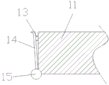
FIG. 4 is a sectional view of a part of the filter screen II;
in the figure: 1. a first filter screen; 2. a support plate; 3. an arc-shaped baffle plate; 4. an elevator control box; 5. a panel; 6. a pin hook; 7. a rotating shaft; 8. a heat radiation fan; 9. a fixing member; 10. a side plate; 11. a second filter screen; 12. down; 13. a spring; 14. a clamping block; 15. a rotating shaft; 101. a filter assembly.
Detailed Description
The technical solutions in the embodiments of the present invention will be clearly and completely described below with reference to the drawings in the embodiments of the present invention, and it is obvious that the described embodiments are only a part of the embodiments of the present invention, and not all of the embodiments. All other embodiments, which can be derived by a person skilled in the art from the embodiments given herein without making any creative effort, shall fall within the protection scope of the present invention.
Referring to fig. 1-4, the present invention provides the following technical solutions: the utility model provides an easy radiating elevator control box, includes elevator control box 4, and 4 one sides of elevator control box are articulated to have panel 5, and multiunit filtering component 101 is installed to its adjacent one side, and filtering component 101 includes: at least two arc baffle 3 that are equipped with opening down and the filter screen two 11 of setting on arc baffle 3 opening, be equipped with the eiderdown 12 that is used for clearing up adjacent filter screen two 11 on one arc baffle 3, and be close to 3 below of arc baffle of elevator control box 4 bottom and still be equipped with a backup pad 2, be equipped with the eiderdown 12 that is used for clearing up 2 top filter screens two 11 of backup pad on the backup pad 2, elevator control box 4 is connected with curb plate 10 through rotation axis 7 with the relative one side of filter assembly 101, guaranteed when radiator fan 8 need overhaul, more convenient and also be difficult for mistake touching the interior electronic components of elevator control box 4, better protection electronic components, curb plate 10 is equipped with logical groove, be equipped with a plurality of mounting 9 on the logical groove, install radiator fan 8 on the mounting 9, install filter screen three on radiator fan 8.
Specifically, one side of the panel 5 close to the elevator control box 4 is provided with a rubber sealing ring, and the other side is provided with a pin hook 6, so that external dust is prevented from entering the elevator control box 4 easily, and electronic components are protected well.
Specifically, still be equipped with temperature sensor in the elevator control box 4, further assurance can the inside temperature of real-time supervision elevator control box 4, when the temperature is higher than preset threshold value, temperature sensor signals gives the PLC controller, radiator fan 8 is given to the PLC controller, make it begin to work, accelerate the peripheral air flow of electronic components in elevator control box 4, take away the heat, keep the temperature throughout the interval of electronic components work in suitable elevator control box 4, make electronic components's performance index more stable, it is also more energy-conserving to start radiator fan 8 according to the temperature simultaneously.
Specifically, 2 belows in backup pad still are equipped with a vent, are equipped with filter screen 1 on the vent, have guaranteed to have carried out the nature heat dissipation in can making outside air get into elevator control box 4, and filter screen 1 has also guaranteed that outside dust is difficult to get into in elevator control box 4.
Specifically, one side of the side plate 10 close to the elevator control box 4 is provided with a convex block, and the elevator control box 4 is provided with a groove matched with the convex block, so that the side plate 10 is ensured to be more tightly attached to the side wall of the elevator control box 4, and external dust is ensured to be not easy to enter the elevator control box 4.
Specifically, two 11 lateral walls of filter screen still are equipped with axis of rotation 15, are equipped with fixture block 14 in the axis of rotation 15, and the fixture block 14 lateral wall passes through spring 13 and two 11 connections of filter screen, and be equipped with on cowl 3 with the draw-in groove of 14 looks adaptations of fixture block, support fixture block 14 through spring 13 for two 11 can be installed on cowl 3 openings, have also made things convenient for subsequent clearance or change, have guaranteed to carry out the quick change with two 11 filter screens.
Through adopting above-mentioned technical scheme, make the outside air get into in the elevator control box 4 through the vent on the elevator control box 4 and the opening on cowl 3, carry out the natural heat dissipation, accelerate the peripheral air flow of electronic components in the elevator control box 4 through a plurality of radiator fan 8 simultaneously, take away the heat, further heat dissipation, wherein through filter screen 1 on the vent and filter screen two 11 on cowl 3 openings and the filter screen three on radiator fan 8, also guaranteed that the outside dust is difficult to get into in the elevator control box 4, drive eiderdown 12 swing through 3 opening circulation of air of cowl simultaneously, also can sweep the attached dust in filter screen two 11 surfaces, it is difficult to blockked up by the dust to have guaranteed that filter screen two 11 are difficult to.
The working principle and the using process of the utility model are as follows: according to the elevator control box easy to dissipate heat, the temperature sensor is arranged in the elevator control box 4, so that the temperature in the elevator control box 4 can be monitored in real time, when the temperature is higher than a preset threshold value, the temperature sensor sends a signal to the PLC, the PLC sends a heat dissipation fan 8 to enable the PLC to start working, air flow around electronic components in the elevator control box 4 is accelerated, heat is taken away, meanwhile, the down feather 12 is driven to swing through air circulation of the opening of the arc-shaped baffle 3, dust attached to the surface of the filter screen II 11 can be swept down, and the filter screen II 11 is guaranteed to be not easily blocked by the dust, so that the operation is completed.
Although embodiments of the present invention have been shown and described, it will be appreciated by those skilled in the art that changes, modifications, substitutions and alterations can be made in these embodiments without departing from the principles and spirit of the utility model, the scope of which is defined in the appended claims and their equivalents.
Claims (6)
1. The utility model provides an easy radiating elevator control box, includes elevator control box (4), its characterized in that: elevator control case (4) one side articulates there is panel (5), and multiunit filtering component (101) are installed to its adjacent one side, filtering component (101) include: at least two arc baffles (3) with downward openings and second filter screens (11) arranged on the openings of the arc baffles (3), wherein one arc baffle (3) is provided with down feather (12) used for cleaning the adjacent second filter screens (11), a supporting plate (2) is arranged below the arc-shaped baffle (3) close to the bottom of the elevator control box (4), the support plate (2) is provided with down feather (12) used for cleaning the second filter screen (11) above the support plate (2), one side of the elevator control box (4) opposite to the filtering component (101) is connected with a side plate (10) through a rotating shaft (7), the side plate (10) is provided with a through groove, the through groove is provided with a plurality of fixing pieces (9), and a heat radiation fan (8) is installed on the fixing piece (9), and a third filter screen is installed on the heat radiation fan (8).
2. The elevator control box easy to dissipate heat according to claim 1, characterized in that: and one side of the panel (5) close to the elevator control box (4) is provided with a rubber sealing ring, and the other side is provided with a pin hook (6).
3. The elevator control box easy to dissipate heat according to claim 1, characterized in that: and a temperature sensor is also arranged in the elevator control box (4).
4. The elevator control box easy to dissipate heat according to claim 1, characterized in that: a ventilation opening is further formed below the supporting plate (2), and a first filter screen (1) is arranged on the ventilation opening.
5. The elevator control box easy to dissipate heat according to claim 1, characterized in that: a convex block is arranged on one side, close to the elevator control box (4), of the side plate (10), and a groove matched with the convex block is formed in the elevator control box (4).
6. The elevator control box easy to dissipate heat according to claim 1, characterized in that: the side wall of the second filter screen (11) is further provided with a rotating shaft (15), a clamping block (14) is arranged on the rotating shaft (15), the side wall of the clamping block (14) is connected with the second filter screen (11) through a spring (13), and a clamping groove matched with the clamping block (14) is formed in the arc-shaped baffle (3).
Priority Applications (1)
| Application Number | Priority Date | Filing Date | Title |
|---|---|---|---|
| CN202122478000.0U CN215835776U (en) | 2021-10-14 | 2021-10-14 | Elevator control box easy to radiate heat |
Applications Claiming Priority (1)
| Application Number | Priority Date | Filing Date | Title |
|---|---|---|---|
| CN202122478000.0U CN215835776U (en) | 2021-10-14 | 2021-10-14 | Elevator control box easy to radiate heat |
Publications (1)
| Publication Number | Publication Date |
|---|---|
| CN215835776U true CN215835776U (en) | 2022-02-15 |
Family
ID=80202715
Family Applications (1)
| Application Number | Title | Priority Date | Filing Date |
|---|---|---|---|
| CN202122478000.0U Active CN215835776U (en) | 2021-10-14 | 2021-10-14 | Elevator control box easy to radiate heat |
Country Status (1)
| Country | Link |
|---|---|
| CN (1) | CN215835776U (en) |
-
2021
- 2021-10-14 CN CN202122478000.0U patent/CN215835776U/en active Active
Similar Documents
| Publication | Publication Date | Title |
|---|---|---|
| CN111542208A (en) | Circulating air-draft type dust removal and heat dissipation device for electromechanical equipment | |
| CN114498396A (en) | Electric power cabinet with heat dissipation function | |
| CN215835776U (en) | Elevator control box easy to radiate heat | |
| CN210298281U (en) | Heat dissipation dust-protection type electrical control cabinet | |
| CN112350197A (en) | Power distribution cabinet capable of automatically radiating heat | |
| CN211930056U (en) | Block terminal with protective structure | |
| CN210007476U (en) | high-efficient heat dissipation type distribution automation monitor terminal | |
| CN114968896A (en) | Server cabinet based on computer information security | |
| CN113382622A (en) | Electromagnetic shielding cabinet with shockproof function | |
| CN114487489A (en) | Safety monitoring device that electrical engineering used | |
| CN209016920U (en) | A kind of radiator structure of frequency converter | |
| CN219304287U (en) | Outdoor electric control cabinet of installation integrates | |
| CN207201216U (en) | Communication cabinet heat abstractor | |
| CN220326098U (en) | Heat dissipation mechanism for frequency converter case | |
| CN219961172U (en) | Heat abstractor for be used for relay protection test equipment | |
| CN219477279U (en) | Dustproof heat dissipation block terminal | |
| CN212096710U (en) | Temperature control protection device for water cutting | |
| CN213338540U (en) | Waterproof host computer is used in network security | |
| CN217642323U (en) | Power distribution cabinet with good heat dissipation | |
| CN218070610U (en) | Control cabinet for power grid power control system | |
| CN212751443U (en) | Internet of things-based outdoor power control cabinet with built-in heat dissipation protection structure | |
| CN213638673U (en) | Automatic control cooling device for coal mine electromechanical equipment | |
| CN219536508U (en) | Data acquisition module | |
| CN217113178U (en) | Protective case for computer control | |
| CN214122896U (en) | Computer network safety control device |
Legal Events
| Date | Code | Title | Description |
|---|---|---|---|
| GR01 | Patent grant | ||
| GR01 | Patent grant |