CN215835363U - Take cup joint formula pivot of solar rack - Google Patents
Take cup joint formula pivot of solar rack Download PDFInfo
- Publication number
- CN215835363U CN215835363U CN202121933010.2U CN202121933010U CN215835363U CN 215835363 U CN215835363 U CN 215835363U CN 202121933010 U CN202121933010 U CN 202121933010U CN 215835363 U CN215835363 U CN 215835363U
- Authority
- CN
- China
- Prior art keywords
- mounting
- fixed
- solar
- plate
- threaded rod
- Prior art date
- Legal status (The legal status is an assumption and is not a legal conclusion. Google has not performed a legal analysis and makes no representation as to the accuracy of the status listed.)
- Active
Links
Images


Classifications
-
- Y—GENERAL TAGGING OF NEW TECHNOLOGICAL DEVELOPMENTS; GENERAL TAGGING OF CROSS-SECTIONAL TECHNOLOGIES SPANNING OVER SEVERAL SECTIONS OF THE IPC; TECHNICAL SUBJECTS COVERED BY FORMER USPC CROSS-REFERENCE ART COLLECTIONS [XRACs] AND DIGESTS
- Y02—TECHNOLOGIES OR APPLICATIONS FOR MITIGATION OR ADAPTATION AGAINST CLIMATE CHANGE
- Y02E—REDUCTION OF GREENHOUSE GAS [GHG] EMISSIONS, RELATED TO ENERGY GENERATION, TRANSMISSION OR DISTRIBUTION
- Y02E10/00—Energy generation through renewable energy sources
- Y02E10/50—Photovoltaic [PV] energy
Landscapes
- Photovoltaic Devices (AREA)
Abstract
The utility model discloses a sleeved rotary shaft with a solar bracket, which comprises a supporting plate, wherein a transmission assembly is movably arranged at the top of the supporting plate, a limiting assembly is fixedly arranged at the top of the transmission assembly, a solar photovoltaic panel is movably arranged in the limiting assembly, an installation assembly is movably arranged at the bottom of the supporting plate, and supporting frames are fixedly arranged on two sides of the installation assembly. According to the solar photovoltaic panel installation structure, the installation assembly is movably installed at the bottom of the support plate, the raised lines on the surface of the sliding rod can be utilized, the raised lines are in limit fit with different limit grooves of the installation cavity, the rotation angle of the sliding rod can be adjusted, the orientation of the solar photovoltaic panel can be adjusted conveniently, meanwhile, the bottom end of the solar support is connected with the first shaft body through the second threaded rod, the nut is screwed after the second threaded rod is in threaded connection with the threaded hole, the position of the solar support can be fixed, and the solar support can be fixed firmly and is convenient to disassemble at a later stage.
Description
Technical Field
The utility model relates to the technical field of solar power supply, in particular to a sleeved rotary shaft with a solar support.
Background
Solar cell panel is through absorbing the sunlight, directly or indirectly convert solar radiation energy into the device of electric energy through photoelectric effect or photochemical effect, most solar cell panel's main material is silicon, for ordinary battery and rechargeable battery that can circulate, solar cell belongs to the green product of more energy-concerving and environment-protective, it needs the support to bear solar cell, need use the pivot between the support, and in the use, there are many problems or defects in the current formula pivot of cup jointing of taking solar support:
traditional take solar rack's cup joint formula pivot in the in-service use, generally all be fixed, inconvenient dismantlement and maintenance, it is very inconvenient to use, and the angle of solar photovoltaic board can't be adjusted simultaneously, can't reasonable improvement resource utilization.
SUMMERY OF THE UTILITY MODEL
The utility model aims to provide a sleeved rotary shaft with a solar bracket to solve the problems in the background technology.
In order to achieve the purpose, the utility model provides the following technical scheme: the utility model provides a take solar rack's cup joint formula pivot, includes the backup pad, the top movable mounting of backup pad has drive assembly, drive assembly's top fixed mounting has spacing subassembly, the inside movable mounting of spacing subassembly has the solar photovoltaic board, the bottom movable mounting of backup pad has the installation component, the equal fixed mounting in both sides of installation component has the support frame, the bottom fixed mounting of installation component has fixed subassembly.
As a further scheme of the utility model: the installation component comprises a first shaft body, a threaded hole is fixedly formed in the top of the first shaft body, a second threaded rod is movably installed inside the threaded hole, a sliding rod is fixedly installed at the bottom of the first shaft body, and a raised line is fixedly installed on the surface of the sliding rod.
As a further scheme of the utility model: the bottom movable mounting of first axis body has the second axis body, it fills up to be fixed being provided with between first axis body and the second axis body fills up, the inside fixed installation cavity that is provided with of the second axis body, the inside fixed spacing groove that is provided with of installation cavity.
As a further scheme of the utility model: the transmission assembly comprises a movable plate, fixed fixing rods are fixedly mounted on two sides of the bottom of the movable plate, a threaded sleeve is fixedly arranged between the fixing rods, a first threaded rod is movably mounted inside the threaded sleeve, a bearing is fixedly mounted at the top of the first threaded rod, a fixed plate is fixedly mounted on one side of the first threaded rod, and a movable shaft is movably mounted at the top of the fixed plate.
As a further scheme of the utility model: the limiting assembly comprises a mounting groove, a limiting plate is mounted on the surface of the mounting groove, a limiting hole is formed in the surface of the limiting plate in a fixed mode, and a pulling plate is fixedly mounted on one side of the limiting plate.
As a further scheme of the utility model: the fixed subassembly includes the fixed slot, the both sides of fixed slot are all fixed mounting have the mounting panel, the fixed sawtooth that is provided with in bottom of mounting panel, the both sides of mounting panel are all fixed mounting have the bolt.
Compared with the prior art, the utility model has the beneficial effects that: this take solar rack's cup joint formula pivot has following advantage:
(1) the installation assembly is movably installed at the bottom of the supporting plate, the raised lines on the surfaces of the sliding rods can be utilized, the raised lines are enabled to be in limit adaptation with different limit grooves of the installation cavity, the rotating angle of the sliding rods can be adjusted, the orientation of a solar photovoltaic panel is convenient to adjust, meanwhile, the bottom end of the solar support is connected with the first shaft body through the second threaded rod, after the second threaded rod is in threaded connection with the threaded hole, the nut is screwed, the position of the solar support can be fixed, the solar support is convenient to disassemble at the later stage after being fixed firmly, and the problems that the traditional solar support is generally fixed, the disassembly and the maintenance are inconvenient and inconvenient to use are solved;
(2) the transmission assembly is movably mounted at the top of the supporting plate, the first threaded rod in the rotary threaded sleeve can be utilized, the first threaded rod rotates to drive the bearing to move, and the angle adjustment of the solar photovoltaic panel is realized by matching with the movable shaft at the top of the fixed plate, so that the problems that the angle of the traditional solar photovoltaic panel cannot be adjusted and the resource utilization rate cannot be reasonably improved are solved;
(3) through the top fixed mounting at drive assembly there is spacing subassembly, through installing the solar photovoltaic board in the mounting groove, pass spacing hole on spacing board surface through external screw and fix, prevent at angle regulation's in-process, the normal work of solar photovoltaic board is influenced to the one end roll-off of solar photovoltaic board from the mounting groove.
Drawings
FIG. 1 is a schematic structural view of the present invention;
FIG. 2 is a top view of a partial structure of the mounting assembly of the present invention;
FIG. 3 is a partial schematic view of the transmission assembly of the present invention;
FIG. 4 is a schematic top view of a portion of the spacing assembly of the present invention;
fig. 5 is a partial structural view of the fixing assembly of the present invention.
In the figure: 1. a transmission assembly; 101. a movable shaft; 102. a fixing plate; 103. moving the plate; 104. fixing the rod; 105. supporting; 106. a first threaded rod; 107. a threaded sleeve; 2. a support plate; 3. mounting the component; 301. a first shaft body; 302. a gasket; 303. a second shaft body; 304. a second threaded rod; 305. a threaded hole; 306. a slide bar; 307. a convex strip; 308. a mounting cavity; 309. a limiting groove; 4. a fixing assembly; 401. mounting a plate; 402. saw teeth; 403. fixing grooves; 404. a bolt; 5. a limiting component; 501. mounting grooves; 502. a limiting hole; 503. lifting the plate; 504. a limiting plate; 6. a support frame; 7. a solar photovoltaic panel.
Detailed Description
The technical solutions in the embodiments of the present invention will be clearly and completely described below with reference to the drawings in the embodiments of the present invention, and it is obvious that the described embodiments are only a part of the embodiments of the present invention, and not all of the embodiments. All other embodiments, which can be derived by a person skilled in the art from the embodiments given herein without making any creative effort, shall fall within the protection scope of the present invention.
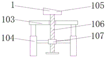
Referring to fig. 1-5, an embodiment of the present invention is shown: a sleeved rotary shaft with a solar bracket comprises a supporting plate 2, a transmission assembly 1 is movably mounted at the top of the supporting plate 2, the transmission assembly 1 comprises a moving plate 103, fixing rods 104 are fixedly mounted on two sides of the bottom of the moving plate 103, threaded sleeves 107 are fixedly arranged between the fixing rods 104, a first threaded rod 106 is movably mounted in each threaded sleeve 107, a bearing 105 is fixedly mounted at the top of each first threaded rod 106, a fixing plate 102 is fixedly mounted on one side of each first threaded rod 106, and a movable shaft 101 is movably mounted at the top of each fixing plate 102;
specifically, as shown in fig. 1 and 3, when the solar photovoltaic panel is used, the transmission assembly 1 is movably mounted at the top of the support plate 2, the first threaded rod 106 inside the rotary threaded sleeve 107 can be utilized, the first threaded rod 106 rotates to drive the bearing 105 to move, and the angle of the solar photovoltaic panel 7 is adjusted by matching with the movable shaft 101 at the top of the fixed plate 102, so that the problems that the angle of the traditional solar photovoltaic panel 7 cannot be adjusted and the resource utilization rate cannot be reasonably improved are solved;
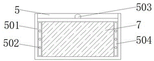
the top of the transmission component 1 is fixedly provided with a limiting component 5, the limiting component 5 comprises an installation groove 501, a limiting plate 504 is installed on the surface of the installation groove 501, a limiting hole 502 is fixedly arranged on the surface of the limiting plate 504, a pulling plate 503 is fixedly installed on one side of the limiting plate 504, and a solar photovoltaic plate 7 is movably installed in the limiting component 5;
specifically, as shown in fig. 1 and 4, when the solar photovoltaic panel adjusting device is used, the limiting assembly 5 is fixedly mounted at the top of the transmission assembly 1, the solar photovoltaic panel 7 is mounted in the mounting groove 501, and the external screw penetrates through the limiting hole 502 on the surface of the limiting plate 504 to be fixed, so that the solar photovoltaic panel 7 is prevented from sliding out of one end of the mounting groove 501 in the angle adjusting process, and the normal work of the solar photovoltaic panel 7 is prevented from being influenced;
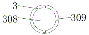
the bottom of the supporting plate 2 is movably provided with a mounting component 3, the mounting component 3 comprises a first shaft body 301, the top of the first shaft body 301 is fixedly provided with a threaded hole 305, the inside of the threaded hole 305 is movably provided with a second threaded rod 304, the bottom of the first shaft body 301 is fixedly provided with a sliding rod 306, the surface of the sliding rod 306 is fixedly provided with a convex strip 307, the bottom of the first shaft body 301 is movably provided with a second shaft body 303, a sealing gasket 302 is fixedly arranged between the first shaft body 301 and the second shaft body 303, the inside of the second shaft body 303 is fixedly provided with a mounting cavity 308, the inside of the mounting cavity 308 is fixedly provided with a limiting groove 309, two sides of the mounting component 3 are both fixedly provided with supporting frames 6, the bottom of the mounting component 3 is fixedly provided with a fixing component 4, the fixing component 4 comprises a fixing groove 403, two sides of the fixing groove 403 are both fixedly provided with a mounting plate 401, the bottom of the mounting plate 401 is fixedly provided with sawteeth 402, bolts 404 are fixedly mounted on both sides of the mounting plate 401;
specifically, as shown in fig. 1, 2 and 5, when in use, the installation component 3 is movably installed at the bottom of the support plate 2, the raised strip 307 on the surface of the sliding rod 306 can be utilized to enable the raised strip 307 to be in limit fit with the different limit grooves 309 of the installation cavity 308, the rotation angle of the sliding rod 306 can be adjusted, the orientation of the solar photovoltaic panel 7 can be conveniently adjusted, meanwhile, the bottom end of the solar bracket is connected with the first shaft body 301 through the second threaded rod 304, the nut is screwed after the second threaded rod 304 is in threaded connection with the threaded hole 305, the position of the solar bracket can be fixed, the solar bracket is convenient to disassemble at the later stage after being fixed firmly, the problems that the traditional solar bracket is generally fixed, inconvenient to disassemble and maintain and inconvenient to use are solved, the fixing component 4 is installed, the fixing groove 403 is arranged to protect the bottom of the second shaft body 303, the solar bracket is fixed through the rotary bolt 404, a plurality of serrations 402 are provided to make the fixing effect better.
The working principle is as follows: when the solar photovoltaic panel fixing device is used, firstly, the mounting assembly 3 is movably mounted at the bottom of the supporting plate 2, the convex strips 307 on the surfaces of the sliding rods 306 can be utilized, the convex strips 307 are in limit fit with different limit grooves 309 of the mounting cavity 308, the rotating angle of the sliding rods 306 can be adjusted, the orientation of the solar photovoltaic panel 7 is convenient to adjust, meanwhile, the bottom end of the solar support is connected with the first shaft body 301 through the second threaded rod 304, the nut is screwed after the second threaded rod 304 is in threaded connection with the threaded hole 305, the position of the solar support can be fixed, and the solar support is convenient to dismount in the later period after being fixed firmly;
secondly, the transmission component 1 is movably mounted at the top of the supporting plate 2, the first threaded rod 106 in the rotary threaded sleeve 107 can be utilized, the first threaded rod 106 rotates to drive the bearing 105 to move, and the angle adjustment of the solar photovoltaic panel 7 is realized by matching with the movable shaft 101 at the top of the fixed plate 102;
finally, there is spacing subassembly 5 through the top fixed mounting at transmission assembly 1, through installing solar photovoltaic board 7 in mounting groove 501, pass limiting hole 502 on limiting plate 504 surface through external screw and fix, prevent at angle regulation's in-process, solar photovoltaic board 7 from the one end roll-off of mounting groove 501, influence the normal work of solar photovoltaic board 7.
It will be evident to those skilled in the art that the utility model is not limited to the details of the foregoing illustrative embodiments, and that the present invention may be embodied in other specific forms without departing from the spirit or essential attributes thereof. The present embodiments are therefore to be considered in all respects as illustrative and not restrictive, the scope of the utility model being indicated by the appended claims rather than by the foregoing description, and all changes which come within the meaning and range of equivalency of the claims are therefore intended to be embraced therein, and any reference signs in the claims are not intended to be construed as limiting the claim concerned.
Claims (6)
1. The utility model provides a take solar rack's cup joint formula pivot, includes backup pad (2), its characterized in that: the top movable mounting of backup pad (2) has drive assembly (1), the top fixed mounting of drive assembly (1) has spacing subassembly (5), the inside movable mounting of spacing subassembly (5) has solar photovoltaic board (7), the bottom movable mounting of backup pad (2) has installation component (3), the both sides of installation component (3) are all fixed mounting have support frame (6), the bottom fixed mounting of installation component (3) has fixed subassembly (4).
2. The sleeved rotary shaft with the solar bracket according to claim 1, wherein: the mounting assembly (3) comprises a first shaft body (301), a threaded hole (305) is fixedly formed in the top of the first shaft body (301), a second threaded rod (304) is movably mounted inside the threaded hole (305), a sliding rod (306) is fixedly mounted at the bottom of the first shaft body (301), and a convex strip (307) is fixedly mounted on the surface of the sliding rod (306).
3. The sleeved rotary shaft with the solar bracket according to claim 2, wherein: the bottom movable mounting of first axis body (301) has second axis body (303), it fills up (302) to fix being provided with between first axis body (301) and the second axis body (303), the inside fixed installation cavity (308) that is provided with of the second axis body (303), the inside fixed spacing groove (309) that is provided with of installation cavity (308).
4. The sleeved rotary shaft with the solar bracket according to claim 1, wherein: drive assembly (1) is including movable plate (103), the both sides of movable plate (103) bottom all fixed mounting have dead lever (104), the fixed thread bush (107) that is provided with between dead lever (104), the inside movable mounting of thread bush (107) has first threaded rod (106), the top fixed mounting of first threaded rod (106) has bearing (105), one side fixed mounting of first threaded rod (106) has fixed plate (102), the top movable mounting of fixed plate (102) has loose axle (101).
5. The sleeved rotary shaft with the solar bracket according to claim 1, wherein: spacing subassembly (5) include mounting groove (501), the surface mounting of mounting groove (501) has limiting plate (504), the fixed surface of limiting plate (504) is provided with spacing hole (502), one side fixed mounting of limiting plate (504) has lifting plate (503).
6. The sleeved rotary shaft with the solar bracket according to claim 1, wherein: fixed subassembly (4) include fixed slot (403), the both sides of fixed slot (403) are all fixed mounting have mounting panel (401), the fixed sawtooth (402) that is provided with in bottom of mounting panel (401), the both sides of mounting panel (401) are all fixed mounting have bolt (404).
Priority Applications (1)
| Application Number | Priority Date | Filing Date | Title |
|---|---|---|---|
| CN202121933010.2U CN215835363U (en) | 2021-08-18 | 2021-08-18 | Take cup joint formula pivot of solar rack |
Applications Claiming Priority (1)
| Application Number | Priority Date | Filing Date | Title |
|---|---|---|---|
| CN202121933010.2U CN215835363U (en) | 2021-08-18 | 2021-08-18 | Take cup joint formula pivot of solar rack |
Publications (1)
| Publication Number | Publication Date |
|---|---|
| CN215835363U true CN215835363U (en) | 2022-02-15 |
Family
ID=80195354
Family Applications (1)
| Application Number | Title | Priority Date | Filing Date |
|---|---|---|---|
| CN202121933010.2U Active CN215835363U (en) | 2021-08-18 | 2021-08-18 | Take cup joint formula pivot of solar rack |
Country Status (1)
| Country | Link |
|---|---|
| CN (1) | CN215835363U (en) |
-
2021
- 2021-08-18 CN CN202121933010.2U patent/CN215835363U/en active Active
Similar Documents
| Publication | Publication Date | Title |
|---|---|---|
| CN213402897U (en) | Fixing and supporting device for solar photovoltaic panel | |
| CN215835363U (en) | Take cup joint formula pivot of solar rack | |
| CN209805733U (en) | photovoltaic power generation solar panel adjusts seat | |
| CN216904759U (en) | Solar panel mounting rack | |
| CN216959751U (en) | Photovoltaic support convenient to angle of adjustment | |
| CN215734152U (en) | Photovoltaic board installing support with adjustable equipment | |
| CN210273921U (en) | Adjustable solar panel's outer wall connecting mechanism | |
| CN213367691U (en) | Base is adjusted to photovoltaic equipment modularization | |
| CN207069977U (en) | A kind of solar panel fixed mount easy to use | |
| CN213879730U (en) | Environment-friendly new energy photovoltaic panel power generation device | |
| CN217159602U (en) | Solar photovoltaic is with installation regulation support | |
| CN216490333U (en) | A solar cell panel fixing device for new forms of energy electricity generation | |
| CN220456991U (en) | Photovoltaic power station grid-connected box convenient to installation | |
| CN210839462U (en) | Composite glass photovoltaic module | |
| CN218940993U (en) | Monocrystalline silicon photovoltaic power generation plate with serially connected crystal elements | |
| CN221597798U (en) | Photovoltaic power generation device convenient to detach | |
| CN211321283U (en) | Photovoltaic aluminum alloy frame easy and convenient to install | |
| CN210120518U (en) | Solar panel support frame for photovoltaic power generation system | |
| CN221103224U (en) | Waterproof type solar panel installation mechanism | |
| CN221648777U (en) | Fixing device of solar flat plate collector | |
| CN220798182U (en) | Adjustable medium voltage device of photovoltaic module | |
| CN219287417U (en) | Photovoltaic board convenient to installation is fixed | |
| CN221467607U (en) | Photovoltaic solar panel convenient to installation | |
| CN219018727U (en) | Photovoltaic cell support frame | |
| CN218006167U (en) | Light energy support of high light energy absorptivity |
Legal Events
| Date | Code | Title | Description |
|---|---|---|---|
| GR01 | Patent grant | ||
| GR01 | Patent grant |