CN215828586U - Bury formula SCBR sewage treatment plant integratedly - Google Patents
Bury formula SCBR sewage treatment plant integratedly Download PDFInfo
- Publication number
- CN215828586U CN215828586U CN202122182343.2U CN202122182343U CN215828586U CN 215828586 U CN215828586 U CN 215828586U CN 202122182343 U CN202122182343 U CN 202122182343U CN 215828586 U CN215828586 U CN 215828586U
- Authority
- CN
- China
- Prior art keywords
- sewage
- threaded rod
- scbr
- sewage treatment
- guide wheel
- Prior art date
- Legal status (The legal status is an assumption and is not a legal conclusion. Google has not performed a legal analysis and makes no representation as to the accuracy of the status listed.)
- Active
Links
Images


Landscapes
- Filtration Of Liquid (AREA)
Abstract
The utility model discloses an integrated buried SCBR sewage treatment device, and belongs to the technical field of sewage treatment equipment. Bury formula SCBR sewage treatment plant integratedly, including handling the case, handle and be equipped with filter chamber, anaerobism chamber, oxidation chamber and clear water chamber in proper order along sewage flow direction in the case, still include: the filtering clapboard is arranged between the filtering cavity and the anaerobic cavity; the sliding block is arranged in the filtering cavity; the roller is arranged in the anaerobic cavity; the first motor is fixedly connected to the treatment box; the sewage containing box is fixedly connected to one side of the treatment box; according to the utility model, sundry sludge attached to the surface of the filtering partition plate and in the through hole can be synchronously cleaned and collected through the scraper arranged on the sliding block in the filtering cavity and the jacking block arranged on the roller in the anaerobic cavity, and the sundry sludge is pushed into the dirt containing box through the cleaning block, so that the problem that the filtering component of the integrated buried SCBR sewage treatment device is blocked and needs to be cleaned manually frequently is avoided, and the sewage treatment efficiency of the integrated buried SCBR sewage treatment device is improved.
Description
Technical Field
The utility model relates to the technical field of sewage treatment equipment, in particular to an integrated buried SCBR sewage treatment device.
Background
The domestic sewage treatment method is characterized in that a large amount of sewage is frequently generated in life, the sewage needs to be treated, if the sewage is not treated, the environment is easily polluted, sewage treatment equipment is often buried underground in a city, the sewage can be treated under the condition that the urban surface is not influenced, the sewage treatment mode is to separately treat industrial sewage, domestic sewage and the like, the domestic sewage is usually treated in modes of precipitation, filtration, disinfection and the like, and the treated sewage is discharged.
The ubiquitous shortcoming of current formula SCBR sewage treatment plant is buried to integration is the problem of blockking up filter assembly easily, needs the manual work often to sewage treatment plant's filter assembly clear up, otherwise can influence formula SCBR sewage treatment plant's that buries to integration sewage treatment efficiency, and the artifical waste a large amount of manpowers of often clearing up.
SUMMERY OF THE UTILITY MODEL
The utility model aims to solve the problem that a filtering component of an integrally buried SCBR sewage treatment device in the prior art is easy to block.
In order to achieve the purpose, the utility model adopts the following technical scheme:
bury formula SCBR sewage treatment plant integratedly, including handling the case, it is equipped with filter chamber, anaerobism chamber, oxidation chamber and clear water chamber in proper order along sewage flow direction in the case to handle, still includes: the filtering partition plate is arranged between the filtering cavity and the anaerobic cavity, and a plurality of through holes are formed in the filtering partition plate; the sliding block is arranged in the filtering cavity, a scraping plate is rotatably connected to the sliding block, and one end, far away from the sliding block, of the scraping plate is attached to the filtering partition plate; the roller is arranged in the anaerobic cavity, wherein a plurality of groups of jacking blocks are fixedly connected to the roller, and the jacking blocks correspond to the through holes; the first motor is fixedly connected to the treatment box and drives the sliding block and the roller to slide up and down in the treatment box through the transmission assembly; the sewage containing box is fixedly connected to one side of the treatment box and is communicated with the treatment box through a sewage inlet hole; the second motor, fixed connection holds dirty case one side, clears up the scraper blade upper surface through clearance subassembly.
In order to drive slider and cylinder displacement about handling the incasement, preferably, drive assembly includes first threaded rod and second threaded rod, first threaded rod rotates to be connected in filtering the intracavity, on the first threaded rod of slider threaded connection, the second threaded rod rotates to be connected in the anaerobism intracavity, threaded connection has the back shaft on the second threaded rod, the cylinder rotates to be connected on the back shaft, first motor passes through interlock mechanism and drives first threaded rod and second threaded rod synchronous revolution.
In order to drive the first threaded rod and the second threaded rod to rotate, the linkage mechanism further comprises a third guide wheel, the third guide wheel is fixedly connected to the output end of the first motor, the top end of the first threaded rod extends to the first guide wheel fixedly connected outside the treatment box, the top end of the second threaded rod extends to the second guide wheel fixedly connected outside the treatment box, and the third guide wheel drives the first guide wheel and the second guide wheel to synchronously rotate through a transmission belt.
In order to ensure that the sliding block and the roller synchronously move up and down in the treatment box, the first threaded rod is provided with two threaded rods, the second threaded rod is provided with two threaded rods, the first threaded rod and the second threaded rod have the same specification, and the first guide wheel and the second guide wheel have the same specification.
Remove about in order to drive the clearance piece, preferably, the clearance subassembly includes reciprocal lead screw, reciprocal lead screw rotates to be connected in the filter chamber, reciprocal lead screw one end extends to flourishing dirty incasement outside with second motor output fixed connection, threaded connection has the clearance piece on the reciprocal lead screw, the clearance piece is corresponding with scraper blade upper surface.
In order to facilitate the cleaning block to push sundry soil to a dirt containing box, the inner wall of the filtering cavity is provided with a through groove, the through groove is communicated with a dirt inlet hole, one side of the filtering cavity corresponding to the through groove is provided with a placing groove, and the cleaning block is positioned in the placing groove.
In order to facilitate the manual cleaning of the sludge in the dirt containing box at regular intervals, preferably, a box cover is rotatably connected to the dirt containing box.
In order to facilitate the introduction of sewage and the discharge of clean water, preferably, two ends of the sewage containing box are respectively and fixedly connected with a water inlet and a water outlet, the water outlet is communicated with the clean water cavity, and the water inlet is communicated with the filter cavity
Compared with the prior art, the utility model provides an integrated buried SCBR sewage treatment device, which has the following beneficial effects:
1. this formula SCBR sewage treatment plant buries integratedly rotates through the positive and negative clearance of first motor and drives slider and cylinder clearance reciprocating motion about handling the incasement orientation to drive scraper blade and kicking block and carry out clearance to filtering baffle and through-hole, thereby what last to filtering baffle on adnexed debris mud clear up and collect.
2. This bury formula SCBR sewage treatment plant integratedly, the rotation groove of seting up on through the slider is to the spacing rotation of scraper blade to make the scraper blade rebound in-process can clear up filtering baffle surface, and the in-process of lapse, scraper blade and filtering baffle surface phase separation, thereby avoid having partial debris mud to be scraped by the scraper blade and collect to the filter chamber bottom.
3. This bury formula SCBR sewage treatment plant integratedly, through the clearance syntropy of second motor drive clearance piece reciprocating motion on reciprocating screw to in clearing up the debris mud that moves to the scraper blade of highest point and promoting to containing thing incasement, so can keep the cleanness on scraper blade surface, thereby guarantee the clean efficiency of scraper blade clearance filtration baffle.
The parts which are not involved in the device are the same as the parts in the prior art or can be realized by adopting the prior art, the utility model can synchronously clean and collect sundry sludge attached to the surface of the filtering partition plate and in the through hole through the scraping plate arranged on the sliding block in the filtering cavity and the jacking block arranged on the roller in the anaerobic cavity, and the sundry sludge is pushed into the dirt containing box through the cleaning block, thereby avoiding the problem that the filtering component of the integrated buried SCBR sewage treatment device is blocked and needs to be cleaned frequently by manpower, and improving the sewage treatment efficiency of the integrated buried SCBR sewage treatment device.
Drawings
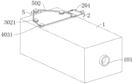
FIG. 1 is a first structural schematic diagram of an integrated buried SCBR sewage treatment plant according to the present invention;
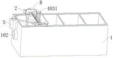
FIG. 2 is a schematic structural diagram II of the integrated buried SCBR sewage treatment plant provided by the utility model;
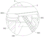
FIG. 3 is a schematic structural view of part A in FIG. 2 of the integrated buried SCBR sewage treatment plant according to the present invention;
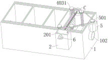
FIG. 4 is a schematic structural view III of the integrated buried SCBR sewage treatment plant provided by the present invention;
FIG. 5 is a schematic structural view of part B of the integrated buried SCBR sewage treatment plant of the present invention shown in FIG. 4;
FIG. 6 is a fourth schematic structural view of the integrated buried SCBR sewage treatment plant provided by the present invention;
FIG. 7 is a schematic structural view of part C in FIG. 6 of the integrated buried SCBR sewage treatment plant according to the present invention;
FIG. 8 is a schematic structural view of the integrated buried SCBR sewage treatment plant slide block according to the present invention.
In the figure: 1. a treatment tank; 101. a water outlet; 102. a water inlet; 103. a filter chamber; 104. an anaerobic chamber; 105. an oxidation chamber; 106. a clear water cavity; 107. a filtering baffle plate; 1071. a through hole; 108. a placement groove; 109. a through groove; 2. a dirt containing box; 201. a box cover; 202. a sewage inlet hole; 3. a slider; 301. a squeegee; 302. a first threaded rod; 3021. a first guide wheel; 4. a drum; 401. a support shaft; 402. a top block; 403. a second threaded rod; 4031. a second guide wheel; 5. a first motor; 501. a third guide wheel; 502. a transmission belt; 6. a second motor; 601. a reciprocating screw rod; 602. and (6) cleaning the blocks.
Detailed Description
The technical solutions in the embodiments of the present invention will be clearly and completely described below with reference to the drawings in the embodiments of the present invention, and it is obvious that the described embodiments are only a part of the embodiments of the present invention, and not all of the embodiments.
In the description of the present invention, it is to be understood that the terms "upper", "lower", "front", "rear", "left", "right", "top", "bottom", "inner", "outer", and the like, indicate orientations or positional relationships based on the orientations or positional relationships shown in the drawings, are merely for convenience in describing the present invention and simplifying the description, and do not indicate or imply that the device or element being referred to must have a particular orientation, be constructed and operated in a particular orientation, and thus, should not be construed as limiting the present invention.
Example 1:
referring to fig. 1-8, formula SCBR sewage treatment plant is buried to integration, including handling case 1, is equipped with filter chamber 103, anaerobism chamber 104, oxidation chamber 105 and clear water chamber 106 along sewage flow direction in proper order in handling case 1, still includes: the filtering partition plate 107 is arranged between the filtering cavity 103 and the anaerobic cavity 104, and a plurality of through holes 1071 are formed in the filtering partition plate 107; the sliding block 3 is arranged in the filtering cavity 103, wherein the sliding block 3 is rotatably connected with a scraping plate 301, and one end of the scraping plate 301, which is far away from the sliding block 3, is attached to the filtering partition plate 107; the roller 4 is arranged in the anaerobic cavity 104, wherein a plurality of groups of top blocks 402 are fixedly connected to the roller 4, and the top blocks 402 correspond to the through holes 1071; the first motor 5 is fixedly connected to the treatment box 1 and drives the sliding block 3 and the roller 4 to slide up and down in the treatment box 1 through the transmission assembly; the sewage containing box 2 is fixedly connected to one side of the treatment box 1, and the sewage containing box 2 is communicated with the treatment box 1 through a sewage inlet hole 202; second motor 6, fixed connection is in flourishing dirty case 2 one side, clears up scraper blade 301 upper surface through the clearance subassembly.
The clearance subassembly includes reciprocal lead screw 601, reciprocal lead screw 601 rotates to be connected in filter chamber 103, reciprocal lead screw 601 one end extends to flourishing dirty case 2 outer with 6 output end fixed connection of second motor, threaded connection has clearance piece 602 on reciprocal lead screw 601, logical groove 109 has been seted up on clearance piece 602 and the corresponding filter chamber 103 inner wall of scraper 301 upper surface, logical groove 109 with advance dirty hole 202 and be linked together, filter chamber 103 is interior to have seted up standing groove 108 with logical groove 109 corresponding one side, clearance piece 602 is located standing groove 108, it is connected with case lid 201 to rotate on the flourishing dirty case 2, flourishing dirty case 2 both ends are fixedly connected with water inlet 102 and delivery port 101 respectively, delivery port 101 is linked together with clear water cavity 106, water inlet 102 is linked together with filter chamber 103.
In order to prevent the related mechanisms such as the first motor 5, the second motor 6, the belt 502, etc. from being easily covered by mud or dust and affecting the operation of the device during the burying process, dust covers may be additionally installed on the processing box 1 and the dirt containing box 2 to protect the related mechanisms such as the first motor 5, the second motor 6, the belt 502, etc. from dust.
In this equipment use, through water inlet 102 with sewage leading-in processing case 1 in, sewage passes through filter chamber 103 filter assembly filtration treatment, through 104 anaerobic bacteria in the anaerobism intracavity with organic matter decomposition in sewage, the aeration equipment further carries out oxidative decomposition to organic matter in the sewage in oxidation chamber 105, flows into clear water chamber 106 at last, through the clear water after delivery port 101 discharge treatment accomplishes.
In the process that the sewage passes through the filtering partition plate 107 in the filtering cavity 103 to filter impurity sludge in the sewage, a large amount of impurity sludge is attached to the surface of the filtering partition plate 107, the first motor 5 and the second motor 6 can be controlled to work by external control equipment, the first motor 5 rotates in a positive and negative clearance manner, and the second motor 6 rotates in a clearance and same direction;
it is to be noted that the control device is specifically a control device that controls processing by a PLC.
When the first motor 5 rotates forwards, the sliding block 3 and the roller 4 can be driven by the transmission assembly to synchronously slide upwards, the scraper 301 can be driven to move upwards in the process that the sliding block 3 slides upwards, the scraper 301 is connected to the rotating groove on the sliding block 3 in a rotating manner, the inner wall of the rotating groove limits the downward rotating angle of the scraper 301, so that the scraper 301 is perpendicular to the surface of the filtering partition plate 107, in the process that the scraper 301 moves upwards, one end of the scraper 301, which is far away from the sliding block 3, can hang down impurity sludge attached to the surface of the filtering partition plate 107 and then attach to the upper surface of the scraper 301 to take away the impurity sludge, in the process that the roller 4 moves upwards, the top block 402 and the through hole 1071 are blocked due to mutual clamping, so that the roller 4 rotates upwards in the process, the top block 402 on the roller 4 is continuously clamped with the through hole 1071 on the filtering partition plate 107, and the impurity sludge in the filtering process in the through hole 1071 is ejected to the left side of the filtering partition plate 107, the scrapers 301 which are synchronously moved scrape and are attached to the surfaces of the scrapers 301, so that the roller 4 and the sliding block 3 are matched with each other in the synchronous upward movement process, and sundries and sludge attached to the surfaces of the filtering partition plates 107 and in the through holes 1071 can be fully removed and scraped.
When the first motor 5 drives the sliding block 3 and the roller 4 to move to the top end of the filtering partition 107, the first motor 5 stops rotating, at the same time, the second motor 6 starts rotating, the second motor 6 drives the reciprocating screw rod 601 to rotate, because the cleaning block 602 is in threaded connection with the reciprocating screw rod 601 and one side of the cleaning block 602 is in fit limit with the surface of the filtering partition 107, during the rotation process of the reciprocating screw rod 601, the cleaning block 602 is driven to move on the reciprocating screw rod 601, at the same time, after the cleaning block 602 slides out of the placing groove 108, the bottom of the cleaning block is in fit with the upper surface of the scraping plate 301 and slides to the direction close to the dirt containing box 2, so that the sludge sundries attached to the upper surface of the scraping plate 301 can be scraped and pushed into the through groove 109 and pushed into the dirt containing box 2 through the through groove 109 and the dirt inlet hole 202, because the reciprocating screw rod 601 is located inside the dirt containing box 2 and is not provided with threads, during the continuous rotation process of the second motor 6, flourishing dirty case 2 can move back, spacing through straining baffle 107 surface, slide to the standing groove 108 in, second motor 6 stall, send next rotation signal until external control equipment, clearance piece 602 can reciprocating motion on reciprocal lead screw 601 under the drive of second motor 6, thereby clear up and collect to flourishing dirty case 2 to scraper blade 301 surface adnexed debris mud in, artifical regular opening case lid 201 to flourishing dirty case 2 in debris mud clear up can, further assurance scraper blade 301 surperficial cleanliness, thereby be convenient for scraper blade 301 to filter baffle 107 and through-hole 1071 in adnexed debris mud clear up, the efficiency of clearance filtering baffle 107 and through-hole 1071 has been improved.
When the cleaning block 602 starts to move back under the driving of the second motor 6, the first motor 5 is started again under the control of the external control device to start to rotate reversely, so as to drive the slide block 3 and the roller 4 to move downwards through the transmission assembly, the roller 4 continues to clean the through hole 1071, and the slide block 3 drives the scraper 301 to move downwards in the downward movement process, at this time, the rotating groove in the slide block 3 does not limit the scraper 301, and the scraper 301 rotates upwards in the rotating groove under the obstruction of the sewage in the filter cavity 103, so that one end of the scraper 301 far away from the slide block 3 is separated from the surface of the filter partition plate 107, and thus, the new attached impurities and sludge on the surface of the filter partition plate 107 can be prevented from being scraped and pushed to the bottom of the filter cavity 103 in the downward movement process of the scraper 301, the filter cavity 103 is inconvenient to clean and scrape when moving upwards, and one end of the scraper 301 far away from the slide block 3 is arc-shaped, so can be convenient for scraper blade 301 upwards rotates at the rotation inslot, and the rotation groove of seting up on the slider 3 is the acute angle opening that makes progress, so when scraper blade 301 upwards rotates the in-process under the hindrance of sewage, can not rotate and reach 90 degrees, can prevent that scraper blade 301 from rotating to when filtering baffle 107 parallel state, can not be quick when scraping filtering baffle 107 surface next time with filtering baffle 107 place face vertical and with filtering baffle 107 surface laminating mutually, thereby lead to the effect variation to filtering baffle 107 surface cleaning, influence the efficiency of clearance filtering baffle 107 and through-hole 1071 interior debris mud, thereby the efficiency of this device treatment sewage has been reduced.
Example 2:
referring to fig. 1 to 8, an integrated buried SCBR sewage treatment apparatus, substantially the same as in example 1, further comprising: the transmission component comprises a first threaded rod 302 and a second threaded rod 403, the first threaded rod 302 is rotatably connected in the filter cavity 103, the sliding block 3 is connected on the first threaded rod 302 in a threaded manner, the second threaded rod 403 is rotatably connected in the anaerobic cavity 104, a supporting shaft 401 is connected on the second threaded rod 403 in a threaded manner, the roller 4 is rotatably connected on the supporting shaft 401, the first motor 5 drives the first threaded rod 302 and the second threaded rod 403 to rotate synchronously through a linkage mechanism, the linkage mechanism comprises a third guide wheel 501, the third guide wheel 501 is fixedly connected at the output end of the first motor 5, the top end of the first threaded rod 302 extends to the outside of the treatment box 1 and is fixedly connected with a first guide wheel 3021, the top end of the second threaded rod extends to the outside of the treatment box 1 and is fixedly connected with a second guide wheel 4031, the third guide wheel 501 drives the first guide wheel 3021 and the second guide wheel 4031 to rotate synchronously through a transmission belt 502, the first threaded rod 302 is provided with two, the second threaded rod 403 is provided with two, the first threaded rod 302 and the second threaded rod 403 are of the same size, and the first guide wheel 3021 and the second guide wheel 4031 are of the same size.
When the first motor 5 rotates, the third guide wheel 501 can be driven to rotate, the third guide wheel 501 drives the first guide wheel 3021 and the second guide wheel 4031 to rotate through the transmission belt 502, the first guide wheel 3021 drives the first threaded rod 302 to rotate, the second guide wheel 4031 drives the second threaded rod 403 to rotate, because two first threaded rods 302 are arranged in parallel and are simultaneously in threaded connection with the sliding block 3, the sliding block 3 can be driven to move up and down along the direction of the first threaded rod 302 during the rotation of the first threaded rod 302, so that the scraping plate 301 can be driven to scrape the surface of the filtering partition 107, two second threaded rods 403 are also arranged in parallel and are simultaneously in threaded connection with the support shaft 401, so that the support shaft 401 can be driven to move up and down along the direction of the second threaded rod 403 during the rotation of the second threaded rod 403, the roller 4 is rotationally connected to the support shaft 401, so that the roller 4 can also move up and down, meanwhile, the top block 402 fixedly connected to the roller 4 is clamped with the through hole 1071, so that the roller 4 can rotate in the vertical displacement process under the combined action of the support shaft 401 and the top block 402, thereby continuously cleaning and ejecting impurity sludge attached to the inside of the through hole 1071, and meanwhile, because the first threaded rod 302 and the second threaded rod 403 have the same specification and size, and the first guide wheel 3021 and the second guide wheel 4031 have the same specification and size, when the driving belt 502 drives the first guide wheel 3021 and the second guide wheel 4031 to rotate simultaneously, the sliding block 3 on the first threaded rod 302 and the roller 4 on the second threaded rod 403 can synchronously move up and down, thereby enabling the scraping plate 301 and the top block 402 to synchronously clean the filtering partition plate 107 and the through hole 1071, and effectively cooperating to clean and collect the impurity sludge attached to the inside the filtering partition plate 107 and the through hole 1071.
According to the utility model, the scraper 301 arranged on the sliding block 3 in the filtering cavity 103 and the jacking block 402 arranged on the roller 4 in the anaerobic cavity 104 can be used for synchronously cleaning and collecting the impurity sludge attached to the surface of the filtering partition plate 107 and the through hole 1071, and the impurity sludge is pushed into the dirt containing box 2 through the cleaning block 602, so that the problem that the filtering component of the integrated buried SCBR sewage treatment device is blocked and needs to be cleaned frequently by manpower is avoided, and the sewage treatment efficiency of the integrated buried SCBR sewage treatment device is improved.
The above description is only for the preferred embodiment of the present invention, but the scope of the present invention is not limited thereto, and any person skilled in the art should be considered to be within the technical scope of the present invention, and equivalent alternatives or modifications according to the technical solution of the present invention and the inventive concept thereof should be covered by the scope of the present invention.
Claims (8)
1. Bury formula SCBR sewage treatment plant integratedly, including handling case (1), it is equipped with filter chamber (103), anaerobism chamber (104), oxidation chamber (105) and clear water chamber (106) along sewage flow direction in proper order to handle in case (1), its characterized in that still includes:
the filtering partition plate (107) is arranged between the filtering cavity (103) and the anaerobic cavity (104), and a plurality of through holes (1071) are formed in the filtering partition plate (107);
a slide block (3) arranged in the filter cavity (103),
the sliding block (3) is rotatably connected with a scraping plate (301), and one end, far away from the sliding block (3), of the scraping plate (301) is attached to the filtering partition plate (107);
a drum (4) arranged in the anaerobic chamber (104),
wherein, a plurality of groups of top blocks (402) are fixedly connected on the roller (4), and the top blocks (402) correspond to the through holes (1071);
the first motor (5) is fixedly connected to the treatment box (1) and drives the sliding block (3) and the roller (4) to move up and down in the treatment box (1) through the transmission assembly;
the sewage containing box (2) is fixedly connected to one side of the treatment box (1), and the sewage containing box (2) is communicated with the treatment box (1) through a sewage inlet hole (202);
and the second motor (6) is fixedly connected to one side of the dirt containing box (2) and is used for cleaning the upper surface of the scraper (301) through a cleaning assembly.
2. The integrally buried SCBR sewage treatment plant according to claim 1, wherein said transmission component comprises a first threaded rod (302) and a second threaded rod (403), said first threaded rod (302) is rotationally connected in the filter chamber (103), said slider (3) is threadedly connected to the first threaded rod (302), said second threaded rod (403) is rotationally connected in the anaerobic chamber (104), said second threaded rod (403) is threadedly connected to the support shaft (401), said drum (4) is rotationally connected to the support shaft (401), said first motor (5) drives the first threaded rod (302) and the second threaded rod (403) to synchronously rotate through the linkage mechanism.
3. The integrally buried SCBR sewage treatment plant according to claim 2, wherein said linkage mechanism comprises a third guide wheel (501), said third guide wheel (501) is fixedly connected to the output end of the first motor (5), the top end of said first threaded rod (302) extends to the outside of the treatment tank (1) and is fixedly connected with a first guide wheel (3021), the top end of said second threaded rod (403) extends to the outside of the treatment tank (1) and is fixedly connected with a second guide wheel (4031), said third guide wheel (501) drives the first guide wheel (3021) and the second guide wheel (4031) to synchronously rotate through the driving belt (502).
4. The integrally buried SCBR sewage treatment plant according to claim 3, wherein said first threaded rod (302) is provided with two, said second threaded rod (403) is provided with two, said first threaded rod (302) and second threaded rod (403) are of the same size, and said first guide wheel (3021) and second guide wheel (4031) are of the same size.
5. The integrally buried SCBR sewage treatment plant according to claim 1, wherein said cleaning assembly comprises a reciprocating screw rod (601), said reciprocating screw rod (601) is rotatably connected in the filter chamber (103), one end of said reciprocating screw rod (601) extends to the outside of the sewage containing tank (2) and is fixedly connected with the output end of the second motor (6), said reciprocating screw rod (601) is connected with a cleaning block (602) by screw thread, said cleaning block (602) corresponds to the upper surface of the scraper (301).
6. The integrally buried SCBR sewage treatment plant according to claim 5, wherein a through slot (109) is opened on the inner wall of said filter chamber (103), said through slot (109) is communicated with said sewage inlet hole (202), a placing slot (108) is opened on the side of said filter chamber (103) corresponding to said through slot (109), and said cleaning block (602) is positioned in said placing slot (108).
7. The integrated buried SCBR sewage treatment plant according to claim 1, wherein a tank cover (201) is rotatably connected to said sewage tank (2).
8. The integrated buried SCBR sewage treatment plant according to claim 1, wherein both ends of said sewage tank (2) are fixedly connected with a water inlet (102) and a water outlet (101) respectively, said water outlet (101) is communicated with a clean water chamber (106), said water inlet (102) is communicated with a filter chamber (103).
Priority Applications (1)
| Application Number | Priority Date | Filing Date | Title |
|---|---|---|---|
| CN202122182343.2U CN215828586U (en) | 2021-09-10 | 2021-09-10 | Bury formula SCBR sewage treatment plant integratedly |
Applications Claiming Priority (1)
| Application Number | Priority Date | Filing Date | Title |
|---|---|---|---|
| CN202122182343.2U CN215828586U (en) | 2021-09-10 | 2021-09-10 | Bury formula SCBR sewage treatment plant integratedly |
Publications (1)
| Publication Number | Publication Date |
|---|---|
| CN215828586U true CN215828586U (en) | 2022-02-15 |
Family
ID=80199121
Family Applications (1)
| Application Number | Title | Priority Date | Filing Date |
|---|---|---|---|
| CN202122182343.2U Active CN215828586U (en) | 2021-09-10 | 2021-09-10 | Bury formula SCBR sewage treatment plant integratedly |
Country Status (1)
| Country | Link |
|---|---|
| CN (1) | CN215828586U (en) |
Cited By (2)
| Publication number | Priority date | Publication date | Assignee | Title |
|---|---|---|---|---|
| CN115212611A (en) * | 2022-09-20 | 2022-10-21 | 山东润泽冷链物流有限公司 | Marine aquaculture sludge sewage treatment equipment |
| CN116061056A (en) * | 2023-01-30 | 2023-05-05 | 广东鸿图(南通)模具有限公司 | Support cut-out press bed die polisher |
-
2021
- 2021-09-10 CN CN202122182343.2U patent/CN215828586U/en active Active
Cited By (4)
| Publication number | Priority date | Publication date | Assignee | Title |
|---|---|---|---|---|
| CN115212611A (en) * | 2022-09-20 | 2022-10-21 | 山东润泽冷链物流有限公司 | Marine aquaculture sludge sewage treatment equipment |
| CN115212611B (en) * | 2022-09-20 | 2023-02-14 | 山东润泽冷链物流有限公司 | Marine aquaculture sludge sewage treatment equipment |
| CN116061056A (en) * | 2023-01-30 | 2023-05-05 | 广东鸿图(南通)模具有限公司 | Support cut-out press bed die polisher |
| CN116061056B (en) * | 2023-01-30 | 2023-12-22 | 广东鸿图(南通)模具有限公司 | Support cut-out press bed die polisher |
Similar Documents
| Publication | Publication Date | Title |
|---|---|---|
| CN215828586U (en) | Bury formula SCBR sewage treatment plant integratedly | |
| CN112978975B (en) | Chemical sewage degradation treatment equipment and method thereof | |
| CN216997916U (en) | Municipal sewage circulation treatment equipment convenient to clearance sewage isolate | |
| CN113248048A (en) | A recycle device for white spirit waste water treatment | |
| CN113830923A (en) | Underground environment-friendly water treatment equipment and using method | |
| CN210786393U (en) | Sludge discharge device for industrial sewage treatment | |
| CN213475548U (en) | Sediment cleaning device for wastewater treatment | |
| CN114772778B (en) | Building construction drainage device | |
| CN214936494U (en) | Sewage purification treatment device | |
| CN213668244U (en) | Waste water detection device with solid-liquid separation mechanism | |
| CN112931394A (en) | Aquaculture bottom of pool dirt suction devic | |
| CN216026859U (en) | Effluent water sump cleaning device | |
| CN217567847U (en) | Sewage treatment device with silt clearance structure | |
| CN217733950U (en) | Small-spacing grid trash remover | |
| CN217231746U (en) | Grab bucket type trash remover for river channel | |
| CN221627175U (en) | Hydraulic engineering dredging device | |
| CN215250092U (en) | Integrated sewage treatment equipment capable of removing sediments | |
| CN221319686U (en) | Oil dirt recovery unit in waste water | |
| CN214808676U (en) | Sewage treatment auxiliary device | |
| CN221131137U (en) | Distributed sewage advanced treatment equipment | |
| CN221014819U (en) | Wastewater utilization device based on urban living discharge | |
| CN221420722U (en) | Sewage treatment pond convenient to inner wall clearance | |
| CN215785477U (en) | Sludge discharge device for treating domestic sewage | |
| CN210885570U (en) | Sewage treatment plant for environmental protection convenient to use | |
| CN220056411U (en) | Industrial water treatment device |
Legal Events
| Date | Code | Title | Description |
|---|---|---|---|
| GR01 | Patent grant | ||
| GR01 | Patent grant |