CN215828076U - Water conservancy hose winding and unwinding device convenient to use - Google Patents
Water conservancy hose winding and unwinding device convenient to use Download PDFInfo
- Publication number
- CN215828076U CN215828076U CN202122034894.4U CN202122034894U CN215828076U CN 215828076 U CN215828076 U CN 215828076U CN 202122034894 U CN202122034894 U CN 202122034894U CN 215828076 U CN215828076 U CN 215828076U
- Authority
- CN
- China
- Prior art keywords
- fixedly connected
- plate
- rotating shaft
- driving rotating
- water conservancy
- Prior art date
- Legal status (The legal status is an assumption and is not a legal conclusion. Google has not performed a legal analysis and makes no representation as to the accuracy of the status listed.)
- Active
Links
Images


Abstract
The utility model discloses a water conservancy hose winding and unwinding device convenient to use, which comprises a working assembly and a limiting assembly, wherein the limiting assembly is fixedly arranged on the right side of the working assembly; the working assembly comprises a bottom plate, a vertical plate is fixedly connected to the left side of the top of the bottom plate, a driving motor is fixedly mounted on the left side of the vertical plate, a driving rotating shaft is fixedly connected to the right end of the driving rotating shaft, the vertical plate is penetrated through the right end of the driving rotating shaft, the right end of the driving rotating shaft extends to the outside of the driving rotating shaft, and a winding drum is sleeved on the surface of the driving rotating shaft. According to the water conservancy hose winding and unwinding device, the working assembly and the limiting assembly are matched with each other, so that the water conservancy hose winding and unwinding device is convenient to use, workers can complete the replacement process of the winding drum with little time and effort, the work burden of the workers is greatly reduced, the work progress of water conservancy construction is accelerated, the practicability is high, and the water conservancy hose winding and unwinding device is suitable for popularization and use.
Description
Technical Field
The utility model relates to the technical field of water conservancy, in particular to a water conservancy hose winding and unwinding device convenient to use.
Background
Various hoses are frequently required to be used in hydraulic engineering, the conventional hydraulic hose winding and unwinding device is inconvenient to use, the work of replacing the whole hose winding drum needs to spend more time and energy of workers, the workload of the workers is greatly increased, the construction process of the hydraulic engineering is slowed, and the practicability is low.
SUMMERY OF THE UTILITY MODEL
The utility model aims to provide a water conservancy hose winding and unwinding device convenient to use, and aims to solve the problems in the background art.
In order to achieve the purpose, the utility model provides the following technical scheme: a water conservancy hose winding and unwinding device convenient to use comprises a working assembly and a limiting assembly, wherein the limiting assembly is fixedly arranged on the right side of the working assembly;
the working assembly comprises a bottom plate, a vertical plate is fixedly connected to the left side of the top of the bottom plate, a driving motor is fixedly mounted on the left side of the vertical plate, a driving rotating shaft is fixedly connected to the right end of the driving motor, the right end of the driving rotating shaft penetrates through the vertical plate and extends to the outside of the vertical plate, a winding drum is sleeved on the surface of the driving rotating shaft, a stop block is fixedly connected to the top and the bottom of the driving rotating shaft and located on the left side of the winding drum, and the right side of the stop block is in contact with the left side of the winding drum;
the limiting component comprises a stabilizing rod movably inserted at the right end of the driving rotating shaft, the right end of the stabilizing rod is fixedly connected with a side plate, the top of the left side of the side plate is fixedly connected with a driving block, the left side of the driving block penetrates through the winding drum and extends to the interior of the winding drum to be movably connected with the winding drum, a first telescopic rod is fixedly connected in the groove at the bottom of the right side of the side plate, a moving plate is fixedly connected at the right end of the first telescopic rod, the surface of the first telescopic rod is sleeved with a spring, the bottom of the left side of the movable plate is fixedly connected with a limiting rod, a second telescopic rod is arranged in the groove at the bottom of the side plate, the bottom end of the second telescopic rod is fixedly connected with a connecting plate, the left end of the limiting rod penetrates through the connecting plate and extends into the connecting plate to be movably connected with the connecting plate, the left side of the top of the connecting plate is fixedly connected with an inserted rod, the top end of the inserted bar penetrates through the driving rotating shaft and the stabilizing rod in sequence and extends to the inside of the stabilizing rod to be movably connected with the stabilizing rod.
Preferably, the bottom fixedly connected with reinforcing block on riser right side, the bottom of reinforcing block and the top fixed connection of bottom plate.
Preferably, the driving rotating shaft is movably connected with the vertical plate.
Preferably, the left end of the spring is fixedly connected with the side plate, and the right end of the spring is fixedly connected with the left side of the moving plate.
Compared with the prior art, the utility model has the following beneficial effects:
1. according to the water conservancy hose winding and unwinding device, the working assembly and the limiting assembly are matched with each other, so that the water conservancy hose winding and unwinding device is convenient to use, workers can complete the replacement process of the winding drum with little time and effort, the work burden of the workers is greatly reduced, the work progress of water conservancy construction is accelerated, the practicability is high, and the water conservancy hose winding and unwinding device is suitable for popularization and use.
2. According to the utility model, the reinforcing blocks are arranged, so that the vertical plate is reinforced, and the vertical plate is prevented from inclining due to bearing more weight.
Drawings
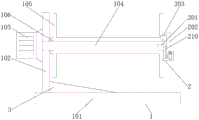
FIG. 1 is a structural cross-sectional view in elevation of the present invention;
FIG. 2 is a structural cross-sectional view of a front view of the spacing assembly of the present invention;
FIG. 3 is a right side view of the stabilizing rod of the present invention.
In the figure: 1 working component, 101 bottom plate, 102 vertical plate, 103 driving motor, 104 driving rotating shaft, 105 winding drum, 106 stop block, 2 limiting component, 201 stabilizing rod, 202 side plate, 203 driving block, 204 first telescopic rod, 205 moving plate, 206 spring, 207 limiting rod, 208 second telescopic rod, 209 connecting plate, 210 inserting rod and 3 reinforcing block.
Detailed Description
The technical solutions in the embodiments of the present invention will be clearly and completely described below with reference to the drawings in the embodiments of the present invention, and it is obvious that the described embodiments are only a part of the embodiments of the present invention, and not all of the embodiments. All other embodiments, which can be derived by a person skilled in the art from the embodiments given herein without making any creative effort, shall fall within the protection scope of the present invention.
Referring to fig. 1-3, a water conservancy hose winding and unwinding device convenient to use includes a working assembly 1 and a limiting assembly 2, wherein the limiting assembly 2 is fixedly installed on the right side of the working assembly 1.
Work assembly 1 includes bottom plate 101, the left side fixedly connected with riser 102 at bottom plate 101 top, the bottom fixedly connected with reinforcement piece 3 on riser 102 right side, the bottom of reinforcement piece 3 and the top fixed connection of bottom plate 101, through setting up reinforcement piece 3, the effect of reinforcing riser 102 has been played, avoid riser 102 to take place to incline because of bearing more weight, the left side fixed mounting of riser 102 has driving motor 103, driving motor 103's right-hand member fixedly connected with drive pivot 104, the right-hand member of drive pivot 104 runs through riser 102 and extends to its outside, swing joint between drive pivot 104 and the riser 102, the surface cover of drive pivot 104 is equipped with winding section of thick bamboo 105, the top and the bottom of drive pivot 104 just are located the equal fixedly connected with dog 106 in winding section of thick bamboo 105's left side, the right side of dog 106 and the left side of winding section of thick bamboo 105 contact each other.
The limiting component 2 comprises a stabilizing rod 201 movably inserted at the right end of the driving rotating shaft 104, a side plate 202 is fixedly connected at the right end of the stabilizing rod 201, a driving block 203 is fixedly connected at the top of the left side of the side plate 202, the left side of the driving block 203 penetrates through the winding drum 105 and extends to the interior of the winding drum to be movably connected with the winding drum, a first telescopic rod 204 is fixedly connected in a groove at the bottom of the right side of the side plate 202, a moving plate 205 is fixedly connected at the right end of the first telescopic rod 204, a spring 206 is sleeved on the surface of the first telescopic rod 204, the left end of the spring 206 is fixedly connected with the side plate 202, the right end of the spring 206 is fixedly connected with the left side of the moving plate 205, a limiting rod 207 is fixedly connected at the bottom of the left side of the moving plate 205, a second telescopic rod 208 is arranged in a groove at the bottom of the side plate 202, a connecting plate 209 is fixedly connected at the bottom end of the second telescopic rod 208, and the left end of the limiting rod 207 penetrates through the connecting plate 209 and extends to the interior of the connecting plate 209 and is movably connected with the connecting plate, left side fixedly connected with inserted bar 210 at connecting plate 209 top, the inside rather than swing joint that drive pivot 104 and firm pole 201 just extended to firm pole 201 is run through in proper order on inserted bar 210's top, through mutually supporting of working component 1 and spacing subassembly 2, water conservancy hose that has realized a facilitate use receives and unreels device, make water conservancy hose receive and releases the rolling device facilitate the use, the change in-process of winding section of thick bamboo 105 just can be accomplished to the staff cost time and energy very few, staff's work burden has greatly been alleviateed, water conservancy construction's work progress has been accelerated, high practicability, and is suitable for being generalized to use.
When the winding device is used, a worker pulls the moving plate 205 rightwards, the moving plate 205 moves to stretch the first telescopic rod 204 and the spring 206, the moving plate 205 drives the limiting rod 207 to be separated from the connecting plate 209, then the connecting plate 209 falls due to weight, the connecting plate 209 drives the inserting rod 210 to be separated from the stabilizing rod 201 and the driving rotating shaft 104, in this way, the side plate 202 is pulled rightwards, the side plate 202 can drive the stabilizing rod 201 to be separated from the driving rotating shaft 104, the driving block 203 is separated from the winding drum 105, finally, the winding drum 105 is pulled rightwards, the winding drum 105 can be taken down from the driving rotating shaft 104, and the whole winding drum 105 is time-saving and labor-saving in the dismounting process.
In summary, the following steps: this water conservancy hose that facilitates use receive and releases coiling mechanism through mutually supporting of working component 1 and spacing subassembly 2, has solved the problem that proposes in the background art.
Although embodiments of the present invention have been shown and described, it will be appreciated by those skilled in the art that changes, modifications, substitutions and alterations can be made in these embodiments without departing from the principles and spirit of the utility model, the scope of which is defined in the appended claims and their equivalents.
Claims (4)
1. The utility model provides a water conservancy hose winding and unwinding device who facilitates use, includes work subassembly (1) and spacing subassembly (2), its characterized in that: the limiting assembly (2) is fixedly arranged on the right side of the working assembly (1);
the working assembly (1) comprises a bottom plate (101), a vertical plate (102) is fixedly connected to the left side of the top of the bottom plate (101), a driving motor (103) is fixedly mounted on the left side of the vertical plate (102), a driving rotating shaft (104) is fixedly connected to the right end of the driving motor (103), the right end of the driving rotating shaft (104) penetrates through the vertical plate (102) and extends to the outside of the driving rotating shaft, a winding drum (105) is sleeved on the surface of the driving rotating shaft (104), a stop block (106) is fixedly connected to the top and the bottom of the driving rotating shaft (104) and is located on the left side of the winding drum (105), and the right side of the stop block (106) is in contact with the left side of the winding drum (105);
the limiting component (2) comprises a stabilizing rod (201) movably inserted at the right end of the driving rotating shaft (104), a side plate (202) is fixedly connected at the right end of the stabilizing rod (201), a driving block (203) is fixedly connected at the top of the left side of the side plate (202), the left side of the driving block (203) penetrates through the winding drum (105) and extends to the interior of the winding drum and is movably connected with the winding drum, a first telescopic rod (204) is fixedly connected in a groove at the bottom of the right side of the side plate (202), a moving plate (205) is fixedly connected at the right end of the first telescopic rod (204), a spring (206) is sleeved on the surface of the first telescopic rod (204), a limiting rod (207) is fixedly connected at the bottom of the left side of the moving plate (205), a second telescopic rod (208) is arranged in a groove at the bottom of the side plate (202), and a connecting plate (209) is fixedly connected at the bottom end of the second telescopic rod (208), the left end of gag lever post (207) runs through connecting plate (209) and extends to its inside rather than swing joint, the left side fixedly connected with inserted bar (210) at connecting plate (209) top, the top of inserted bar (210) runs through drive pivot (104) and stabilizing rod (201) in proper order and extends to the inside rather than swing joint of stabilizing rod (201).
2. The water conservancy hose receive and releases coiling apparatus that facilitates use of claim 1, its characterized in that: the bottom fixedly connected with reinforcing block (3) on riser (102) right side, the bottom of reinforcing block (3) and the top fixed connection of bottom plate (101).
3. The water conservancy hose receive and releases coiling apparatus that facilitates use of claim 1, its characterized in that: the driving rotating shaft (104) is movably connected with the vertical plate (102).
4. The water conservancy hose receive and releases coiling apparatus that facilitates use of claim 1, its characterized in that: the left end of the spring (206) is fixedly connected with the side plate (202), and the right end of the spring (206) is fixedly connected with the left side of the moving plate (205).
Priority Applications (1)
| Application Number | Priority Date | Filing Date | Title |
|---|---|---|---|
| CN202122034894.4U CN215828076U (en) | 2021-08-26 | 2021-08-26 | Water conservancy hose winding and unwinding device convenient to use |
Applications Claiming Priority (1)
| Application Number | Priority Date | Filing Date | Title |
|---|---|---|---|
| CN202122034894.4U CN215828076U (en) | 2021-08-26 | 2021-08-26 | Water conservancy hose winding and unwinding device convenient to use |
Publications (1)
| Publication Number | Publication Date |
|---|---|
| CN215828076U true CN215828076U (en) | 2022-02-15 |
Family
ID=80197551
Family Applications (1)
| Application Number | Title | Priority Date | Filing Date |
|---|---|---|---|
| CN202122034894.4U Active CN215828076U (en) | 2021-08-26 | 2021-08-26 | Water conservancy hose winding and unwinding device convenient to use |
Country Status (1)
| Country | Link |
|---|---|
| CN (1) | CN215828076U (en) |
-
2021
- 2021-08-26 CN CN202122034894.4U patent/CN215828076U/en active Active
Similar Documents
| Publication | Publication Date | Title |
|---|---|---|
| CN111346781A (en) | Device is paintd to release agent for building templates | |
| CN110644791A (en) | Concrete pouring platform is built in room | |
| CN215828076U (en) | Water conservancy hose winding and unwinding device convenient to use | |
| CN214925398U (en) | Prefabricated reinforced concrete wallboard mould | |
| CN211393540U (en) | Steel member hoist and mount auxiliary device | |
| CN114427200A (en) | Suspension device for bridge engineering construction | |
| CN213143057U (en) | Rope saw for cutting CFG pile head | |
| CN210131923U (en) | Concrete pipe pile wire drawing machine | |
| CN210439695U (en) | Aluminum template reinforcing apparatus | |
| CN211247778U (en) | Wire rewinding mechanism for cable drawing machine | |
| CN213836651U (en) | Bridge construction is with pile device | |
| CN207476517U (en) | A kind of Water saving type watering arrangement based on agricultural development | |
| CN220684437U (en) | Brake disc conveying device | |
| CN220351562U (en) | Cable-stayed device of tower crane | |
| CN219259392U (en) | Hoisting structure | |
| CN215366752U (en) | Afforestation construction marking device | |
| CN214543341U (en) | Device for laying communication pole line suspension wire in long distance | |
| CN219929228U (en) | Tractor convenient to overhaul | |
| CN215159538U (en) | But winder of quick replacement winding roller | |
| CN215406244U (en) | Water supply and drainage dredging device | |
| CN210457375U (en) | Hanging basket convenient for adjusting station | |
| CN219098346U (en) | Combined pipe coiling machine | |
| CN215716975U (en) | Wall whitewashing machine | |
| CN219060920U (en) | Concrete conveying device | |
| CN220804011U (en) | Maintenance equipment |
Legal Events
| Date | Code | Title | Description |
|---|---|---|---|
| GR01 | Patent grant | ||
| GR01 | Patent grant |