CN215802715U - Roof waterproof construction is used in construction in room - Google Patents
Roof waterproof construction is used in construction in room Download PDFInfo
- Publication number
- CN215802715U CN215802715U CN202120654915.XU CN202120654915U CN215802715U CN 215802715 U CN215802715 U CN 215802715U CN 202120654915 U CN202120654915 U CN 202120654915U CN 215802715 U CN215802715 U CN 215802715U
- Authority
- CN
- China
- Prior art keywords
- roof
- shaped
- bases
- waterproofing membrane
- waterproof
- Prior art date
- Legal status (The legal status is an assumption and is not a legal conclusion. Google has not performed a legal analysis and makes no representation as to the accuracy of the status listed.)
- Active
Links
Images



Landscapes
- Building Environments (AREA)
Abstract
The utility model provides a roof waterproof structure for building construction, which relates to the technical field of roof construction and comprises a plurality of rows of parallel bases and clamping pieces clamped in the bases, wherein the bases are fixed in a roof, U-shaped grooves with upward openings are arranged on the bases, and the top and the roofing parallel and level of base, waterproofing membrane lays between adjacent base, adjacent waterproofing membrane's side alternately lays in the U type recess of base, joint spare include T type main part and with T type main part sliding connection's slider, the spout has been seted up respectively to the vertical part's of T type main part both sides, be provided with the spring on the spout cell wall, the slider sets up in the spout and with spring coupling, T type main part is inserted and is located in U type recess, spring extrusion slider presss from both sides waterproofing membrane in locating U type spout, the horizontal part extrusion waterproofing membrane of T type main part supports and leans on in the roofing, the waterproofing membrane overlap joint department on roof among the solution prior art easily splits the problem that the gap leads to the roof seepage.
Description
Technical Field
The utility model belongs to the technical field of roof construction, and particularly provides a roof waterproof structure for building construction.
Background
The roof is used as a component of the uppermost layer of the building, waterproof and drainage measures are required to be taken, which is a difficult problem in building engineering, and the whole service life of the house is influenced due to the fact that the waterproof measures of the roof are not well treated. In order to prevent water leakage from the roof, a waterproof roll is usually laid on the surface of the roof to enhance the waterproof performance of the roof.
But the roof area is great, and waterproofing membrane is when laying, and a slice piece bonds or the overlap joint is in the same place usually, and the junction of adjacent coiled material splits easily in the long-term use, appears the gap, and the leakproofness between the adjacent waterproofing membrane reduces, and in the rainy day, the rainwater can flow in waterproofing membrane's below and infiltration wall body through the gap, waterproofing membrane's leakproofness greatly reduced.
Accordingly, there is a need in the art for a roof waterproofing structure for building construction to solve the above problems.
SUMMERY OF THE UTILITY MODEL
The utility model provides a roof waterproof structure for building construction, which solves the problem that in the prior art, a lap joint of a waterproof coiled material of a roof is easy to crack, and cracks are generated to cause roof leakage.
The technical scheme of the utility model is realized as follows: a roof waterproof structure for building construction comprises a plurality of rows of parallel bases and clamping pieces, wherein the bases are perpendicular to a roof and arranged along the water direction, the clamping pieces are clamped in the bases, the bases are fixed in the roof, U-shaped grooves with upward openings are formed in the bases, the top ends of the bases are flush with the roof, waterproof coiled materials are laid between the adjacent bases, the side edges of the adjacent waterproof coiled materials are alternately laid in the U-shaped grooves of the bases, each clamping piece comprises a T-shaped main body and a sliding block which is in sliding connection with the T-shaped main body, sliding grooves with openings facing the side walls of the U-shaped grooves are formed in two sides of the vertical part of the T-shaped main body respectively, springs are arranged on the groove walls of the sliding grooves opposite to the side walls of the U-shaped grooves, the sliding blocks are arranged in the sliding grooves and connected with the springs, and the T-shaped main bodies are inserted in the U-shaped grooves, spring extrusion in the slider is located U type spout with waterproofing membrane clamp, the horizontal part extrusion waterproofing membrane of T type main part supports and leans on in the roofing.
The technical effect of the scheme is as follows: the T-shaped main body of the clamping piece is inserted into the U-shaped groove of the base, the fixing of the side edges of adjacent waterproof coiled materials is achieved, the waterproof coiled materials are paved in the U-shaped groove of the base in a crossed mode, the crossed portion of the adjacent waterproof coiled materials is extruded by the bottom of the vertical portion of the T-shaped main body, the waterproof coiled materials are clamped between the bottom of the vertical portion and the bottom of the U-shaped groove, the waterproof coiled materials located on the side wall of the U-shaped groove are extruded by a spring extrusion sliding block in the T-shaped main body, the waterproof coiled materials are clamped between the sliding block and the side wall of the U-shaped groove, the transverse portion of the T-shaped main body abuts against the portion, located on a roof, of the waterproof coiled materials, and the waterproof coiled materials are extruded between the transverse portion and the roof; the waterproof structure has the advantages that gaps can not be formed between adjacent waterproof rolls, rainwater is prevented from entering the lower portions of the waterproof rolls, and the waterproof performance of a roof is enhanced.
In the above-mentioned roof waterproof construction's for building construction preferred technical scheme, the slider comprises isosceles trapezoid structure and cuboid structure, and when the spring was in under the natural state, the cuboid structure was located in the spout, isosceles trapezoid structure exposes in external environment, the base angle of the vertical part of T type main part sets up to the chamfer.
The technical effect of the scheme is as follows: when the waterproof coiled material is laid in the U-shaped groove of the base, a bent part is formed in the notch of the U-shaped groove, and when the clamping piece is inserted into the base, the inclined plane of the isosceles trapezoid structure of the sliding block is firstly contacted with the bent part of the waterproof coiled material, so that the sliding blocks on two sides of the T-shaped main body can smoothly enter the U-shaped groove, and the damage of the sliding blocks to the waterproof coiled material is avoided; in a similar way, the bottom of the T-shaped main body is provided with the chamfer, so that the damage to the waterproof coiled material caused by the sharp corner is avoided, and the waterproof performance of the waterproof coiled material is ensured.
In the above preferable technical scheme of the roof waterproof structure for building construction, the base comprises a bottom plate and two limiting plates arranged on the bottom plate, the two limiting plates are arranged in parallel and integrally formed with the base, and the U-shaped groove is formed between the two limiting plates.
The technical effect of the scheme is as follows: the arrangement of the bottom plate facilitates the fixed connection between the base and the roof, and the stability of the base is ensured; the limiting plate and the base are integrally formed, so that the manufacturing is convenient, and the strength of the base is guaranteed.
In the preferred technical scheme of building construction roof waterproof construction in above-mentioned room, waterproofing membrane lays to parapet top and extends to parapet back from roofing one side, the roof waterproof construction for the building construction still includes the transition scute, the transition scute is used for placing in the corner that roofing and parapet link up, one side that the scute deviates from the corner is provided with the arcwall face towards the turning concave yield, just the both sides limit of arcwall face extends to parapet and roofing respectively, the scute passes through the screw and is connected with the parapet, just the arcwall face is seted up the hidden groove that holds the spiral shell head of screw, and waterproofing membrane pastes and locates the arcwall face.
The technical effect of the scheme is as follows: because the parapet drenches after soaking the erosion for a long time through the rainwater and can be unstable, lay waterproofing membrane to the parapet one side of roofing back of the body, can form water protection to the parapet, but waterproofing membrane buckles for a long time at the corner that roofing and parapet link up, waterproofing membrane fracture can take place, lead to the rainwater to get into waterproofing membrane below and parapet root, form the erosion to roofing and parapet bottom, through setting up the transition scute, form the arcwall at the corner, avoid waterproofing membrane transition to buckle, guarantee waterproofing membrane's integrality and waterproof performance.
In the preferred technical scheme of roof waterproof construction for the construction is built in above-mentioned room, still include the reinforcement, the reinforcement includes first L template and second L template, the movable slot has been seted up in the transverse part of first L template, the transverse part of second L template is inserted and is located in the movable slot, with movable slot sliding connection, the transverse part of second L template with be provided with the spring between the movable slot, when the vertical part of first L template and second L template pressed from both sides and locates the both sides of parapet, the spring was in tensile state.
The technical effect of the scheme is as follows: waterproofing membrane on the parapet experiences after the long-term wind blows the sun, easily drops from the parapet on the wall, through setting up the reinforcement, press from both sides the vertical part of first L template and second L template and establish in the parapet both sides, it is fixed to form the extrusion to the waterproofing membrane of parapet both sides, the horizontal part of first L template and second L template simultaneously shelters from and protects the top formation of parapet, avoids the erosion of rainwater, improves the waterproof performance of parapet.
Drawings
In order to more clearly illustrate the embodiments of the present invention or the technical solutions in the prior art, the drawings used in the description of the embodiments or the prior art will be briefly described below, and it is obvious that the drawings in the following description are only some embodiments of the present invention, and for those skilled in the art, other drawings can be obtained according to these drawings without creative efforts.
FIG. 1 is a cross-sectional view of a base and a clip of a roof waterproof structure for house construction according to the present invention;
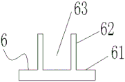
FIG. 2 is a schematic view of a base of a roof waterproof structure for building construction according to the present invention;
FIG. 3 is a schematic view of a clip of a roof waterproof structure for building construction according to the present invention;
FIG. 4 is a sectional view showing a reinforcing member and a transition gusset for a roof waterproofing structure for building construction according to the present invention in use.
List of reference numerals: 01. pouring a large plate; 1. a vapor barrier; 2. a heat-insulating layer; 3. leveling layer; 4. a protective layer; 5. waterproof coiled materials; 6. a base; 61. a base plate; 62. a limiting plate; 63. a U-shaped groove; 7. a clamping piece; 71. a T-shaped body; 711. a chute; 72. a slider; 8. a parapet wall; 9. a reinforcement; 91. a first L-shaped plate; 911. a movable groove; 92. a second L-shaped plate; 10. a transition gusset; 101. the slot is hidden.
Detailed Description
The technical solutions in the embodiments of the present invention will be clearly and completely described below with reference to the drawings in the embodiments of the present invention, and it is obvious that the described embodiments are only a part of the embodiments of the present invention, and not all of the embodiments. All other embodiments, which can be derived by a person skilled in the art from the embodiments given herein without making any creative effort, shall fall within the protection scope of the present invention.
It should be noted that in the description of the present invention, the terms "center", "upper", "lower", "left", "right", "vertical", "horizontal", "inner", "outer", etc. indicating the directions or positional relationships are based on the directions or positional relationships shown in the drawings, which are only for convenience of description, and do not indicate or imply that the device or element must have a specific orientation, be constructed and operated in a specific orientation, and thus, should not be construed as limiting the present invention. Furthermore, the terms "first" and "second" are used for descriptive purposes only and are not to be construed as indicating or implying relative importance.
The utility model relates to a concrete embodiment of a roof waterproof structure for building construction, which comprises the following steps: as shown in fig. 1, the roof comprises a pouring large plate 01, a steam-insulating layer 1, a heat-insulating layer 2, a leveling layer 3, a protective layer 4 and a waterproof coiled material 5 which are sequentially arranged from bottom to top. Roof waterproof construction for building construction includes the base 6 and the joint 7 of joint in base 6 of a plurality of rows of parallels that the perpendicular to roofing set up along the water direction.
As shown in fig. 1 and fig. 2, the base 6 is poured in the leveling layer 3, and with roofing fixed connection, the base 6 includes the bottom plate 61 and sets up two limiting plates 62 on the bottom plate 61, and relative parallel arrangement and with base 6 integrated into one piece about two limiting plates 62 form U type recess 63 between two limiting plates 62, and the up end of two limiting plates 62 and the up end parallel and level of protective layer 4. Waterproofing membrane 5 lays between adjacent base 6, and adjacent waterproofing membrane 5's side is alternately laid in the U type recess 63 of base 6.
As shown in fig. 3, the clip 7 includes a T-shaped main body 71 and a slider 72 slidably connected to the T-shaped main body 71, sliding grooves 711 opened toward the side walls of the U-shaped groove 63 are respectively formed on two sides of the vertical portion of the T-shaped main body 71, a spring is disposed on the groove wall of the sliding groove 711 opposite to the side walls of the U-shaped groove 63, and the slider 72 is disposed in the sliding groove 711 and connected to the spring. When the spring is in a natural state, namely, the spring is not influenced by external force, one part of the sliding block 72 is positioned in the sliding groove 711, the other part of the sliding block 72 is positioned outside the sliding groove 711, and the distance between the sides of the two sliding blocks 72, which are away from each other, is larger than the groove width of the U-shaped groove 63.
Continuing to refer to fig. 1, the waterproof rolls 5 are alternately laid in the U-shaped groove 63 of the base 6, the T-shaped main body 71 of the joint member 7 is inserted into the U-shaped groove 63 of the base 6, the bottom of the vertical portion of the T-shaped main body 71 presses the intersecting portion of the adjacent waterproof rolls 5 to be clamped between the bottom of the vertical portion and the bottom of the U-shaped groove 63, the spring pressing slider 72 in the T-shaped main body 71 presses the waterproof rolls 5 located on the side wall of the U-shaped groove 63 to clamp the waterproof rolls 5 between the slider 72 and the side wall of the U-shaped groove 63, the horizontal portion of the T-shaped main body 71 abuts against the portion of the waterproof rolls 5 located on the roof, the waterproof rolls 5 are pressed between the horizontal portion and the roof, so that no gap is formed between the adjacent waterproof rolls 5, thereby preventing rainwater from entering the lower portion of the waterproof rolls 5 and enhancing the waterproof performance of the roof.
Referring again to fig. 2, because waterproofing membrane 5 lays in the U type recess 63 of base 6, can form the part of buckling at the notch of U type recess 63, when joint spare 7 inserts in base 6, slider 72 may be mixed by the card in the notch, inconvenient entering or cause wearing and tearing to waterproofing membrane 5, therefore, in this embodiment, slider 72 comprises isosceles trapezoid structure and cuboid structure, two waists of isosceles trapezoid structure are located upper and lower direction respectively, when the spring is in under the natural state, the cuboid structure is located spout 711, the isosceles trapezoid structure exposes in external environment, the base angle of the vertical part of T type main part 71 sets up to the chamfer.
When the clamping piece 7 is inserted into the base 6, the inclined plane of the isosceles trapezoid structure of the sliding block 72 contacts with the bent part of the waterproof roll 5 first, so that the sliding blocks 72 on the two sides of the T-shaped main body 71 can smoothly enter the U-shaped groove 63, and the sliding block 72 is prevented from damaging the waterproof roll 5; in a similar way, the bottom of the T-shaped main body 71 is provided with a chamfer, so that the damage to the waterproof roll material 5 caused by sharp edges and corners is avoided, and the waterproof performance of the waterproof roll material 5 is ensured.
As shown in fig. 4, since the parapet 8 is unstable after long-term rain and rain erosion, in this embodiment, the waterproof roll 5 is laid to the side of the parapet 8 away from the roof, so as to protect the parapet 8 from water, but the waterproof roll 5 on the parapet 8 is prone to falling off from the parapet 8 after long-term wind blowing and sun exposure. Therefore, the present embodiment is provided with the reinforcement 9.
Reinforcing member 9 includes first L template 91 and second L template 92, movable slot 911 has been seted up in the horizontal part of first L template 91, the horizontal part of second L template 92 is inserted and is located in movable slot 911, with movable slot 911 sliding connection, be provided with the spring between the horizontal part of second L template 92 and the movable slot 911, when the vertical part of first L template 91 and second L template 92 pressed from both sides of locating parapet 8, the spring is in tensile state, it is fixed to form the extrusion to the waterproofing membrane 5 of parapet 8 both sides, the horizontal part of first L template 91 and second L template 92 forms shelters from and protects the top of parapet 8 simultaneously, avoid the erosion of rainwater, improve the waterproof performance of parapet 8.
When waterproofing membrane 5 was laid on parapet 8, can form at the corner that roofing and parapet 8 link up and buckle, waterproofing membrane 5 buckles for a long time, easily takes place damage and fracture, leads to the rainwater to get into 5 below of waterproofing membrane and 8 roots of parapet, forms the erosion to roofing and 8 bottoms of parapet. Therefore, the roof waterproof structure for house construction is further provided with the transition gusset 10. Transition scute 10 is placed in the corner that roofing and parapet 8 link up, one side that the scute deviates from the corner is provided with the arcwall face towards the turning concave yield, and the both sides limit of arcwall face extends to parapet 8 and roofing respectively, the scute passes through the screw to be connected with parapet 8, waterproofing membrane 5 pastes and locates the arcwall face, the hidden groove 101 that holds the spiral shell head of screw is seted up to the arcwall face, avoid the spiral shell head jack-up waterproofing membrane 5 of screw, cause 5 bulges of waterproofing membrane, influence water-proof effects.
In the above embodiments, the base is poured into the leveling layer of the roof, and the upper end surface of the base is flush with the upper end surface of the protective layer, in other embodiments, the base may be fixed in a suitable structural layer according to the composition of the roof, and the upper end surface of the base is kept flush with the roof before the waterproof roll layer is laid.
In the above-mentioned embodiment, the base includes the bottom plate and with two limiting plates of bottom plate integrated into one piece, in other embodiments, the limiting plate still can weld on the bottom plate, perhaps the base still can set up to the structure of falling T style of calligraphy, the U type recess that the opening upwards was seted up to the vertical part of the structure of falling T style of calligraphy.
In the above embodiment, the slider is composed of an isosceles trapezoid structure and a rectangular parallelepiped structure, and in other embodiments, the slider may further be configured to be composed of a right trapezoid structure and a rectangular parallelepiped structure, wherein the waist of the right trapezoid structure is located below.
The present invention is not limited to the above preferred embodiments, and any modifications, equivalent substitutions, improvements, etc. within the spirit and principle of the present invention should be included in the protection scope of the present invention.
Claims (5)
1. A roof waterproof structure for building construction is characterized by comprising a plurality of rows of parallel bases and clamping pieces, wherein the bases are perpendicular to a roof and arranged along the water direction, the clamping pieces are clamped in the bases, the bases are fixed in the roof, U-shaped grooves with upward openings are formed in the bases, the top ends of the bases are flush with the roof, waterproof coiled materials are paved between adjacent bases, the side edges of adjacent waterproof coiled materials are crossed and paved in the U-shaped grooves of the bases, each clamping piece comprises a T-shaped main body and a sliding block in sliding connection with the T-shaped main body, sliding grooves with openings facing the side walls of the U-shaped grooves are respectively formed in two sides of the vertical part of the T-shaped main body, springs are arranged on the groove walls, opposite to the side walls of the U-shaped grooves, of the sliding grooves, the sliding blocks are arranged in the sliding grooves and connected with the springs, and the T-shaped main bodies are inserted in the U-shaped grooves, spring extrusion in the slider is located U type spout with waterproofing membrane clamp, the horizontal part extrusion waterproofing membrane of T type main part supports and leans on in the roofing.
2. The roof waterproof structure for house construction according to claim 1, wherein the slider is composed of an isosceles trapezoid structure and a cuboid structure, when the spring is in a natural state, the cuboid structure is located in the sliding groove, the isosceles trapezoid structure is exposed in an external environment, and a bottom angle of a vertical portion of the T-shaped main body is set to be a chamfer.
3. The roof waterproof structure for building construction according to claim 2, wherein the base includes a bottom plate and two limiting plates disposed on the bottom plate, the two limiting plates are disposed in parallel and integrally formed with the base, and the U-shaped groove is formed between the two limiting plates.
4. The roof waterproof structure for building construction according to claim 1 or 3, wherein the waterproof roll is laid on the top end of the parapet wall and extends to the side of the parapet wall away from the roof, the roof waterproof structure for building construction further comprises a transition angle plate, the transition angle plate is used for being placed at a corner where the roof is connected with the parapet wall, an arc-shaped surface facing a concave corner is arranged on the side of the angle plate away from the corner, two side edges of the arc-shaped surface respectively extend to the parapet wall and the roof, the angle plate is connected with the parapet wall through a screw, a hidden groove for containing a screw head of the screw is formed in the arc-shaped surface, and the waterproof roll is attached to the arc-shaped surface.
5. The roof waterproof structure for building construction according to claim 4, further comprising a reinforcing member, wherein the reinforcing member comprises a first L-shaped plate and a second L-shaped plate, a movable groove is formed in a transverse portion of the first L-shaped plate, the transverse portion of the second L-shaped plate is inserted into the movable groove and is slidably connected with the movable groove, a spring is arranged between the transverse portion of the second L-shaped plate and the movable groove, and when the vertical portions of the first L-shaped plate and the second L-shaped plate are clamped on two sides of the parapet, the spring is in a stretching state.
Priority Applications (1)
| Application Number | Priority Date | Filing Date | Title |
|---|---|---|---|
| CN202120654915.XU CN215802715U (en) | 2021-03-31 | 2021-03-31 | Roof waterproof construction is used in construction in room |
Applications Claiming Priority (1)
| Application Number | Priority Date | Filing Date | Title |
|---|---|---|---|
| CN202120654915.XU CN215802715U (en) | 2021-03-31 | 2021-03-31 | Roof waterproof construction is used in construction in room |
Publications (1)
| Publication Number | Publication Date |
|---|---|
| CN215802715U true CN215802715U (en) | 2022-02-11 |
Family
ID=80162928
Family Applications (1)
| Application Number | Title | Priority Date | Filing Date |
|---|---|---|---|
| CN202120654915.XU Active CN215802715U (en) | 2021-03-31 | 2021-03-31 | Roof waterproof construction is used in construction in room |
Country Status (1)
| Country | Link |
|---|---|
| CN (1) | CN215802715U (en) |
Cited By (1)
| Publication number | Priority date | Publication date | Assignee | Title |
|---|---|---|---|---|
| CN114673372A (en) * | 2022-03-15 | 2022-06-28 | 北京城建亚泰金典建设工程有限公司 | Waterproof coiled material stubble throwing protection structure and construction method |
-
2021
- 2021-03-31 CN CN202120654915.XU patent/CN215802715U/en active Active
Cited By (2)
| Publication number | Priority date | Publication date | Assignee | Title |
|---|---|---|---|---|
| CN114673372A (en) * | 2022-03-15 | 2022-06-28 | 北京城建亚泰金典建设工程有限公司 | Waterproof coiled material stubble throwing protection structure and construction method |
| CN114673372B (en) * | 2022-03-15 | 2023-09-12 | 北京城建亚泰金典建设工程有限公司 | Waterproof coiled material stubble-throwing protection structure and construction method |
Similar Documents
| Publication | Publication Date | Title |
|---|---|---|
| CN215802715U (en) | Roof waterproof construction is used in construction in room | |
| CN212026888U (en) | Waterproof eaves gutter of pitched roof | |
| CN210439569U (en) | Ancient building roof waterproof construction | |
| CN208441369U (en) | Assembled architecture preventing water leakage, anticlogging gutter structure | |
| CN106481008A (en) | A kind of China Democratic National Construction Association's building construction | |
| CN208934289U (en) | A kind of fixed device of architectural engineering technology waterproofing design waterproof roll laying | |
| CN213062448U (en) | Waterproof seam structure of building | |
| CN214941733U (en) | Parapet energy-saving component based on assembly type building | |
| CN214884940U (en) | Waterproof construction of roofing and concrete wall handing-over department | |
| CN115897910B (en) | Reverse ridge type roof expansion joint structure and construction method thereof | |
| CN211897656U (en) | Low-carbon environment-friendly brick for building | |
| CN215888941U (en) | Waterproof and pressure-resistant sintered red brick | |
| CN212773220U (en) | Anti-leakage structure of roof deformation joint | |
| CN211341461U (en) | Eaves mouth structure convenient to arrange rain | |
| CN218479409U (en) | Waterproof roofing of fine aggregate concrete | |
| CN211597117U (en) | Roof deformation joint waterproof construction | |
| CN214834304U (en) | Combined type water seepage-proof external wall brick | |
| CN109881847A (en) | Deformation joint drain structure equipped with basement roof outdoor ground or roofing | |
| CN109914668A (en) | Nuclear power factory building roof is anti-to throw building structure | |
| CN214364473U (en) | Double-slope ridge node waterproof structure | |
| CN211114462U (en) | Corner waterproof structure for photovoltaic module clamping system | |
| CN215858653U (en) | Combined waterproof layer structure of top plate of green belt underground engineering | |
| CN217128776U (en) | Inboard roofing gutter structure of parapet | |
| CN219241108U (en) | Waterproof structure for high-low span deformation joint of planted roof and outer wall | |
| KR102510073B1 (en) | Solor Roof Panel |
Legal Events
| Date | Code | Title | Description |
|---|---|---|---|
| GR01 | Patent grant | ||
| GR01 | Patent grant |