CN215800983U - Module comb plate multidirectional corner expansion device - Google Patents
Module comb plate multidirectional corner expansion device Download PDFInfo
- Publication number
- CN215800983U CN215800983U CN202120192989.6U CN202120192989U CN215800983U CN 215800983 U CN215800983 U CN 215800983U CN 202120192989 U CN202120192989 U CN 202120192989U CN 215800983 U CN215800983 U CN 215800983U
- Authority
- CN
- China
- Prior art keywords
- comb tooth
- plate
- movable comb
- tooth assembly
- movable
- Prior art date
- Legal status (The legal status is an assumption and is not a legal conclusion. Google has not performed a legal analysis and makes no representation as to the accuracy of the status listed.)
- Active
Links
- 244000126211 Hericium coralloides Species 0.000 claims abstract description 48
- 238000006073 displacement reaction Methods 0.000 claims description 11
- 230000000694 effects Effects 0.000 abstract description 7
- 230000009467 reduction Effects 0.000 abstract description 6
- 238000002955 isolation Methods 0.000 abstract description 4
- 238000010521 absorption reaction Methods 0.000 abstract description 3
- 238000005516 engineering process Methods 0.000 description 2
- 230000006872 improvement Effects 0.000 description 2
- 230000005906 menstruation Effects 0.000 description 2
- 229910052751 metal Inorganic materials 0.000 description 2
- 239000002184 metal Substances 0.000 description 2
- 230000035939 shock Effects 0.000 description 2
- 229910001220 stainless steel Inorganic materials 0.000 description 2
- 239000010935 stainless steel Substances 0.000 description 2
- 229910000831 Steel Inorganic materials 0.000 description 1
- 230000009471 action Effects 0.000 description 1
- 239000002390 adhesive tape Substances 0.000 description 1
- 239000004411 aluminium Substances 0.000 description 1
- 229910052782 aluminium Inorganic materials 0.000 description 1
- XAGFODPZIPBFFR-UHFFFAOYSA-N aluminium Chemical compound [Al] XAGFODPZIPBFFR-UHFFFAOYSA-N 0.000 description 1
- 230000003139 buffering effect Effects 0.000 description 1
- 238000013016 damping Methods 0.000 description 1
- 230000007547 defect Effects 0.000 description 1
- 230000001066 destructive effect Effects 0.000 description 1
- 238000010586 diagram Methods 0.000 description 1
- 230000005489 elastic deformation Effects 0.000 description 1
- 238000000034 method Methods 0.000 description 1
- 238000012986 modification Methods 0.000 description 1
- 230000004048 modification Effects 0.000 description 1
- 230000008569 process Effects 0.000 description 1
- 239000010959 steel Substances 0.000 description 1
Images

Landscapes
- Bridges Or Land Bridges (AREA)
Abstract
The utility model discloses a multidirectional corner expansion device of a module comb plate, which comprises a fixed comb tooth assembly and a movable comb tooth assembly, wherein the fixed comb tooth assembly and the movable comb tooth assembly are respectively connected and matched with main beams at two sides of a bridge expansion joint, so that the fixed comb tooth assembly and the movable comb tooth assembly are in alignment fit; the movable comb tooth assembly comprises a movable comb tooth plate, a corner deflection box and a plurality of connecting bolts for connecting the movable comb tooth plate and the main beam; a rubber cushion plate is clamped at the connecting position of the connecting bolt and the movable comb plate; when the vibration isolation and noise reduction device is implemented, the rubber base plates are arranged at the connecting bolts of the movable comb plate, so that the rubber base plates can be matched with the corner deflection box to realize vibration absorption and rotary deformation, and the vibration isolation and noise reduction effects can be realized.
Description
Technical Field
The utility model relates to a multidirectional corner expansion device, in particular to a module comb plate multidirectional corner expansion device.
Background
The bridge expansion device is an important component for bridge structure safety, and has the function of meeting the displacement requirements of longitudinal, vertical, torsion and the like of a bridge under the action of external force such as air temperature, wind power, load, ground vibration and the like, so that vehicles can stably and safely pass through an expansion joint area. In the actual use process, most of the deflection does not exist independently, and often occurs in a cross comprehensive manner, so that the bridge expansion device must meet the complex deflection of the bridge under various conditions, the normal operation of the device is ensured, and the driving safety is ensured. On the other hand, the destructive power of the complex displacements is effectively eliminated, and the driving comfort is ensured.
Present multidirectional telescoping device of fishback is structural comparatively simple, specific saying so, its structure mainly comprises fixed fishback, activity fishback and corner case that shifts, it is the corner case that shifts that wherein mainly undertakes the function of shifting, but the structure of the case that shifts of present corner is comparatively simple, the shock attenuation effect is poor, more specifically say, it is the hard connection structure that the telescoping device used to become, though can realize the activity displacement, nevertheless lack the buffering design on the swing joint position, and the bridge telescoping device is mostly metal such as steel aluminium and constitutes, this just makes the bridge telescoping device because the metal striking can produce great sound and vibrations when the vehicle menstruation, influence the travelling comfort of vehicle when the menstruation bridge.
In summary, there is still much room and need for improvement in the multi-direction angle telescopic device.
SUMMERY OF THE UTILITY MODEL
The utility model aims to overcome the defects in the prior art and provides the modular comb plate multidirectional corner expansion device which is reasonable in structural design and good in damping effect.
In order to achieve the purpose, the technical scheme adopted by the utility model is as follows:
a module comb plate multidirectional corner expansion device comprises a fixed comb tooth assembly and a movable comb tooth assembly, wherein the fixed comb tooth assembly and the movable comb tooth assembly are respectively connected and matched with main beams at two sides of a bridge expansion joint, so that the fixed comb tooth assembly and the movable comb tooth assembly are in alignment fit;
the fixed comb tooth assembly comprises a fixed comb tooth plate and a plurality of connecting bolts for connecting the fixed comb tooth plate and the main beam;
the movable comb tooth assembly comprises a movable comb tooth plate, a corner deflection box and a plurality of connecting bolts for connecting the movable comb tooth plate and the main beam;
a rubber cushion plate is clamped at the connecting position of the connecting bolt and the movable comb plate;
the corner deflection box is connected and matched with the movable comb plate;
the side surface of the corner deflection box is fixedly matched with the main beam through a bolt;
the corner displacement box comprises a box body, a plurality of rotating shaft supporting seats and a rotating shaft, wherein the rotating shaft supporting seats are arranged in the box body;
the rotating shaft is fixedly connected with the bottom surface of the movable comb plate;
a movable gap is left between the two ends of the rotating shaft and the two end surfaces of the box body.
Furthermore, the box body is a square box body with an open upper part, and the cross section of the box body is U-shaped.
Furthermore, a buffer rubber block is arranged between the box body of the corner deflection box and the movable comb-tooth plate.
Furthermore, a waterproof rubber strip is arranged between the fixed comb tooth assembly and the movable comb tooth assembly.
Furthermore, the rotating shaft is a smooth shaft, and the contact surface of the rotating shaft supporting seat and the rotating shaft is also a smooth surface.
Furthermore, in the above technical solution, the number of the rotating shaft supporting seats is preferably three.
When the vibration isolation and noise reduction device is implemented, the rubber base plates are arranged at the connecting bolts of the movable comb plate, so that the rubber base plates can be matched with the corner deflection box to realize vibration absorption and rotary deformation, and the vibration isolation and noise reduction effects can be realized.
Drawings
The accompanying drawings, which are incorporated in and constitute a part of this specification, illustrate embodiments of the specification and together with the description, serve to explain the principles of the specification.
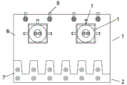
Fig. 1 is a schematic structural view of the present invention.
Fig. 2 is a schematic structural diagram of another view angle of the present invention.
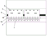
Fig. 3 is a schematic structural view of the present invention in practice.
The reference numbers in the figures are respectively: (1) the device comprises a fixed comb tooth assembly, (2) a movable comb tooth assembly, (3) a main beam, (4) a main beam, (5) a bridge expansion joint, (6) a fixed comb plate, (7) a movable comb plate, (8) an angle deflection box, (9) a connecting bolt, (10) a connecting bolt, (11) a rubber cushion plate, (12) a box body, (13) a rotating shaft supporting seat, (14) a rotating shaft, (15) a movable gap, (16) a buffer rubber block, (17) a waterproof rubber strip and (18) a stainless steel sliding plate.
Detailed Description
The following description of at least one exemplary embodiment is merely illustrative in nature and is in no way intended to limit the disclosure, its application, or uses.
It should be noted that like reference numerals and letters refer to like items in the following figures, and thus, once an item is defined in one figure, further discussion thereof is not required in subsequent figures.
In the description of the present invention, it should be noted that the terms "vertical", "upper", "lower", "horizontal", and the like indicate orientations or positional relationships based on those shown in the drawings, and are only for convenience of describing the present invention and simplifying the description, but do not indicate or imply that the referred device or element must have a specific orientation, be constructed in a specific orientation, and be operated, and thus, should not be construed as limiting the present invention.
In the description of the present invention, it is also to be noted that the terms "disposed," "mounted," "connected," and "connected" are to be construed broadly unless otherwise specifically stated or limited. The specific meanings of the above terms in the present invention can be understood by those skilled in the art according to specific situations.
Example (b):
as shown in fig. 1-3, the utility model comprises a fixed comb component 1 and a movable comb component 2, wherein the fixed comb component 1 and the movable comb component 2 are respectively connected and matched with main beams 3 and 4 at two sides of a bridge expansion joint 5, so that the fixed comb component 1 is aligned and matched with the movable comb component 2; the fixed comb tooth assembly 1 comprises a fixed comb tooth plate 6 and a plurality of connecting bolts 10 for connecting the fixed comb tooth plate 6 with the main beam 4;
the movable comb tooth assembly 2 comprises a movable comb tooth plate 7, a corner deflection box 8 and a plurality of connecting bolts 9 for connecting the movable comb tooth plate 7 and the main beam 3; a rubber cushion plate 11 is clamped at the connecting position of the connecting bolt 9 and the movable comb plate 7; the corner deflection box 8 is connected and matched with the movable comb plate 7; the side surface of the corner displacement box 8 is fixedly matched with the main beam 3 through a bolt; the corner displacement box 8 comprises a rectangular box body 12 with a U-shaped section, three rotating shaft supporting seats 13 arranged in the box body 12 and a rotating shaft 14 matched with the rotating shaft supporting seats 13; the rotating shaft 14 is fixedly connected with the bottom surface of the movable comb plate 7; a movable gap 15 is left between the two ends of the rotating shaft 14 and the two end faces of the box body 12.
Because the rubber backing plate 11 has good deformation adaptability, the sufficient bearing capacity can be ensured, and the vertical displacement of the movable comb plate 7 can be realized in a matching way to play the main role of shock absorption and noise reduction.
And because the movable clearance 15 is left between the two ends of the rotating shaft 14 and the two end faces of the box body, the movable comb plate 7 can have a certain deformation space when being horizontally stressed, and the requirement of displacement deformation of the bridge in the horizontal direction is met.
For example, with continued reference to fig. 1, a buffer rubber block 16 is installed between the box body 12 of the corner displacement box 8 and the movable comb plate 7; a waterproof adhesive tape 17 is arranged between the fixed comb tooth assembly 1 and the movable comb tooth assembly 2; the rotating shaft 14 is a smooth shaft, and the contact surface between the rotating shaft supporting seat 13 and the rotating shaft 14 is also a smooth surface. Because the buffer rubber block 16 has elastic deformation capacity and good deformation adaptability, the enough bearing capacity can be ensured, the vertical deflection of the movable comb plate 7 can be realized, and a certain vibration and noise reduction effect is realized.
It should be noted that the waterproof rubber strip 17 plays a waterproof role,
with reference to fig. 3, when the above-mentioned technology is implemented, the fixed comb tooth assembly 1 and the movable comb tooth assembly 2 are respectively installed on the two side main beams 3, 4 of the bridge expansion joint 5 and are aligned and matched to form a multi-directional corner expansion device of the comb plate, the multi-directional corner expansion device of the comb plate is of a modular design, and a plurality of multi-directional corner expansion devices of the comb plate can be connected and arranged along the seam direction on the two side main beams 3, 4 of the expansion joint 5 according to the width of the bridge expansion joint 5. When the bridge is deformed in a telescopic manner, the module comb plate multidirectional corner telescopic device can perform displacement compensation in the horizontal direction and the vertical direction.
In the above example, it is further noted that a stainless steel slide plate 18 for guiding is also generally installed between the fixed comb-tooth assembly 1 and the movable comb-tooth assembly 2.
The foregoing description of the embodiments of the present specification has been presented for purposes of illustration and description, but is not intended to be exhaustive or limited to the embodiments disclosed. Many modifications and variations will be apparent to those of ordinary skill in the art without departing from the scope and spirit of the described embodiments. The terminology used herein is chosen in order to best explain the principles of the embodiments, the practical application, or improvements made to the technology in the marketplace, or to enable others of ordinary skill in the art to understand the embodiments disclosed herein. The scope of the application is defined by the appended claims.
Claims (2)
1. The utility model provides a multidirectional corner telescoping device of module fishback which characterized in that: the fixed comb tooth assembly and the movable comb tooth assembly are respectively connected and matched with main beams at two sides of a bridge expansion joint, so that the fixed comb tooth assembly and the movable comb tooth assembly are matched in an alignment way; the fixed comb tooth assembly comprises a fixed comb tooth plate and a plurality of connecting bolts for connecting the fixed comb tooth plate and the main beam; the movable comb tooth assembly comprises a movable comb tooth plate, a corner deflection box and a plurality of connecting bolts for connecting the movable comb tooth plate and the main beam; a rubber cushion plate is clamped at the connecting position of the connecting bolt and the movable comb plate; the corner deflection box is connected and matched with the movable comb plate.
2. A modular comb plate multi-way corner telescoping device as claimed in claim 1, wherein: the corner displacement box comprises a box body, a plurality of rotating shaft supporting seats and a rotating shaft, wherein the rotating shaft supporting seats are arranged in the box body; the rotating shaft is fixedly connected with the bottom surface of the movable comb plate; a movable gap is left between the two ends of the rotating shaft and the two end surfaces of the box body.
Priority Applications (1)
| Application Number | Priority Date | Filing Date | Title |
|---|---|---|---|
| CN202120192989.6U CN215800983U (en) | 2021-01-25 | 2021-01-25 | Module comb plate multidirectional corner expansion device |
Applications Claiming Priority (1)
| Application Number | Priority Date | Filing Date | Title |
|---|---|---|---|
| CN202120192989.6U CN215800983U (en) | 2021-01-25 | 2021-01-25 | Module comb plate multidirectional corner expansion device |
Publications (1)
| Publication Number | Publication Date |
|---|---|
| CN215800983U true CN215800983U (en) | 2022-02-11 |
Family
ID=80125677
Family Applications (1)
| Application Number | Title | Priority Date | Filing Date |
|---|---|---|---|
| CN202120192989.6U Active CN215800983U (en) | 2021-01-25 | 2021-01-25 | Module comb plate multidirectional corner expansion device |
Country Status (1)
| Country | Link |
|---|---|
| CN (1) | CN215800983U (en) |
-
2021
- 2021-01-25 CN CN202120192989.6U patent/CN215800983U/en active Active
Similar Documents
| Publication | Publication Date | Title |
|---|---|---|
| JP2006257674A (en) | Building seismic control structure | |
| CN215800983U (en) | Module comb plate multidirectional corner expansion device | |
| JP4232454B2 (en) | Damping structure of bridge | |
| JP5199687B2 (en) | Damping device, damping structure, and damping panel | |
| JP2002213531A (en) | Damping damper device | |
| JP2002302377A (en) | Base isolation type crane | |
| JPH03204369A (en) | Body bending vibration preventing device and installation method thereof | |
| CN215104628U (en) | Steel damping bearing with space universality | |
| JPH0344519Y2 (en) | ||
| CN113136975B (en) | A fully decoupled vibration dual control device | |
| JPWO2006129534A1 (en) | XY guidance device | |
| CN210288751U (en) | A wooden sliding friction damper with variable damping force | |
| CN113308987A (en) | Steel damping support with space universality | |
| CN220266291U (en) | Vibration-proof noise-reduction multidirectional deflection expansion device for bridge | |
| JP2011080486A (en) | Vibration damping structure | |
| CN114809767B (en) | Displacement amplification type mild steel damper | |
| CN112627376A (en) | Energy dissipation shock-absorbing structure and damper displacement amplification device | |
| CN219773255U (en) | Variable-order metal yield damper | |
| JP4595261B2 (en) | Damper of vibration isolator | |
| JP3663563B2 (en) | Seismic isolation device | |
| JP2000320183A (en) | Mounting structure of seismic isolation device and building with seismic isolation device | |
| CN223723936U (en) | Friction buckling two-stage composite damper | |
| CN218562073U (en) | Multidirectional-displacement expansion device for comb-tooth type bridge | |
| CN216074716U (en) | Bridge bearing and bridge structure | |
| JP2002213528A (en) | Damping damper device |
Legal Events
| Date | Code | Title | Description |
|---|---|---|---|
| GR01 | Patent grant | ||
| GR01 | Patent grant |