CN215766370U - Hot air generating equipment for drying light bricks - Google Patents
Hot air generating equipment for drying light bricks Download PDFInfo
- Publication number
- CN215766370U CN215766370U CN202121990041.1U CN202121990041U CN215766370U CN 215766370 U CN215766370 U CN 215766370U CN 202121990041 U CN202121990041 U CN 202121990041U CN 215766370 U CN215766370 U CN 215766370U
- Authority
- CN
- China
- Prior art keywords
- air
- fixedly connected
- pipe
- drying
- side wall
- Prior art date
- Legal status (The legal status is an assumption and is not a legal conclusion. Google has not performed a legal analysis and makes no representation as to the accuracy of the status listed.)
- Active
Links
Images


Landscapes
- Drying Of Solid Materials (AREA)
Abstract
The utility model discloses hot air generating equipment for drying light bricks, which comprises a supporting base, wherein the upper end surface of the supporting base is fixedly connected with two symmetrically arranged supporting plates, an air pipe is rotatably connected between the two supporting plates, air inlets are formed in the side walls of the left end and the right end of the air pipe, an installation frame is fixedly connected in the air pipe, driving fan blades are rotatably connected on the installation frame, a plurality of heating blocks are circumferentially and fixedly connected on the inner side wall of the air pipe, an adjusting mechanism for adjusting the orientation of an air outlet of the air pipe is arranged on the side wall of the air pipe, and a driving mechanism for providing driving power for the adjusting mechanism is arranged on the upper end surface of the supporting base. According to the utility model, through arranging the air inlet pipe, the heating block, the air inlet and other structures, secondary heating circulation is carried out through air sucked into the environment in the forward direction and heated, so that the energy consumption of the heated air is reduced, the air heating efficiency is improved, and the brick drying efficiency is effectively improved.
Description
Technical Field
The utility model relates to the technical field of hot air generating devices, in particular to hot air generating equipment for drying light bricks.
Background
The light brick is foamed brick, and the normal indoor partition wall is made of the brick, so that the floor load is effectively reduced, the sound insulation effect is good, the strength product is made of high-quality tabular corundum and mullite as aggregate, sillimanite composite as matrix, special additive and a small amount of rare earth oxide through mixing, high-pressure forming and high-temperature firing. The common light heat-insulating refractory brick is made of clay, high-alumina high-strength floating bead brick, low-iron mullite, high-alumina light heat-insulating refractory brick and diatomite heat-insulating refractory brick.
Light brick is in process of production, need carry out drying process to the brick body under specific environment after the brick body shaping, the mode that adopts usually is the air heater drying, it air-dries the processing to the internal moisture of brick through the circulation that produces hot-blast fan drive air promptly, this kind of mode is when using, because current fan is when using, it is to pass through the low temperature wind that inhales more, carry out heat treatment afterwards, this kind of mode is when using, at first low temperature air heating needs heating time and heating energy consumption, the temperature of heating simultaneously is not high, consequently, lead to its drying efficiency lower.
SUMMERY OF THE UTILITY MODEL
The utility model aims to solve the defects in the prior art and provides hot air generating equipment for drying light bricks.
In order to achieve the purpose, the utility model adopts the following technical scheme:
the utility model provides a hot-blast emergence is equipped for light brick is dry, includes and supports the base, support the backup pad that two symmetries of up end fixedly connected with of base set up, two rotate between the backup pad and be connected with the tuber pipe, the air intake has all been seted up on the both ends lateral wall about the tuber pipe, fixedly connected with mounting bracket in the tuber pipe, it is connected with the drive flabellum to rotate on the mounting bracket, a plurality of heating pieces of circumference fixedly connected with on the tuber pipe inside wall, be equipped with on the tuber pipe lateral wall and be used for the adjustment mechanism who adjusts tuber pipe air outlet orientation, the up end that supports the base is equipped with and is used for providing actuating power's actuating mechanism for adjustment mechanism.
Preferably, adjustment mechanism is including rotating the rotation screw rod of connection at the support base up end, it is the lead screw rod to rotate the screw rod, the cover is equipped with lifting sleeve on the rotation screw rod, it is connected with the telescopic shaft to rotate on lifting sleeve's the rear side lateral wall, sliding sleeve is equipped with movable strut on the lateral wall of telescopic shaft, movable strut rotates to be connected on the lateral wall of tuber pipe.
Preferably, the driving mechanism comprises a driving motor fixedly connected to the upper end face of the supporting base, an output shaft of the driving motor is fixedly connected with a worm, a worm wheel is fixedly connected to the side wall of the rotating screw rod, and the worm is meshed with the worm wheel.
Preferably, a plurality of controllers are fixedly connected to the side wall of the air pipe in the circumferential direction, and the controllers are electrically connected to the heating block.
Preferably, air inlet pipes are fixedly connected to the side walls of the left end and the right end of the air pipe, and the air inlet pipes are communicated with the air inlets.
Preferably, the end face of the rear side of the air duct is a sealing structure.
Compared with the prior art, the utility model has the beneficial effects that:
1. through setting up air-supply line, heating piece and air intake isotructure, carry out the secondary heating circulation through the air that forward inhales in the environment and be heated, reduce heated air's energy consumption, improve the efficiency of air heating simultaneously, the dry efficiency of the effectual promotion brick body.
2. Through setting up adjustment mechanism and actuating mechanism, utilize among the actuating mechanism worm and worm wheel cooperation transmission to drive the lifting sleeve who rotates on the screw rod to the reciprocating drive of activity strut, realize the up-and-down reciprocating motion process of tuber pipe promptly, increase the dryable area of tuber pipe, improve the dry efficiency of brick body.
Drawings
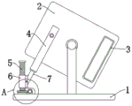
FIG. 1 is a schematic left-view structural diagram of a hot air generating device for drying lightweight bricks according to the present invention;
FIG. 2 is a schematic front view of a hot wind generating device for drying lightweight bricks according to the present invention;
fig. 3 is an enlarged schematic view of a structure at a position a in fig. 1 of the hot air generating equipment for drying the light bricks according to the present invention.
In the figure: the device comprises a support base 1, an air pipe 2, an air inlet 3, a movable support frame 4, a rotating screw rod 5, a lifting sleeve 6, a telescopic shaft 7, a worm wheel 8, a driving motor 9, a worm 10, an air inlet pipe 11, a controller 12, a heating block 13, a driving fan blade 14 and a mounting rack 15.
Detailed Description
In order to make the aforementioned objects, features and advantages of the present invention comprehensible, embodiments accompanied with figures are described in detail below. In the following description, numerous specific details are set forth in order to provide a thorough understanding of the present invention. This invention may, however, be embodied in many different forms and should not be construed as limited to the embodiments set forth herein, but rather should be construed as broadly as the present invention is capable of modification in various respects, all without departing from the spirit and scope of the present invention.
It will be understood that when an element is referred to as being "secured to" another element, it can be directly on the other element or intervening elements may also be present. When an element is referred to as being "connected" to another element, it can be directly connected to the other element or intervening elements may also be present. The terms "vertical," "horizontal," "left," "right," and the like as used herein are for illustrative purposes only and do not represent the only embodiments.
Referring to fig. 1-3, a hot air generating device for drying lightweight bricks comprises a supporting base 1, wherein the upper end surface of the supporting base 1 is fixedly connected with two symmetrically arranged supporting plates, an air pipe 2 is rotatably connected between the two supporting plates, air inlets 3 are respectively formed in the side walls of the left end and the right end of the air pipe 2, an installation frame 15 is fixedly connected in the air pipe 2, a driving fan blade 14 is rotatably connected on the installation frame 15, and a plurality of heating blocks 13 are circumferentially and fixedly connected on the inner side wall of the air pipe 2;
a plurality of controllers 12 are fixedly connected to the side wall of the air duct 2 in the circumferential direction, and the controllers 12 are electrically connected to the heating block 13.
Be equipped with on 2 lateral walls of tuber pipe and be used for the adjustment mechanism who adjusts the air outlet orientation of tuber pipe 2, adjustment mechanism is including rotating the rotation screw rod 5 of connection at the support base 1 up end, it is the lead screw rod to rotate screw rod 5, it is equipped with lifting sleeve 6 to rotate the cover on the screw rod 5, it is connected with telescopic shaft 7 to rotate on lifting sleeve 6's the rear side lateral wall, the slip cover is equipped with movable strut 4 on the lateral wall of telescopic shaft 7, movable strut 4 rotates to be connected on the lateral wall of tuber pipe 2.
The up end that supports base 1 is equipped with the actuating mechanism who is used for providing drive power for adjustment mechanism, and actuating mechanism includes fixed connection at the driving motor 9 who supports base 1 up end, and driving motor 9's output shaft fixedly connected with worm 10 rotates fixedly connected with worm wheel 8 on the lateral wall of screw rod 5, and worm 10 meshes worm wheel 8.
When the utility model is used, as shown in fig. 1-3, in operation, the fan blades 14 are driven to rotate on the mounting frame 15, air is sucked in through the air inlet 3 and the air inlet pipe 11, then the heating temperature of the heating block 13 is adjusted and controlled by the adjusting controller 12, then the heated air is discharged through the air pipe 2, because the air inlet direction of the air inlet pipe 11 is consistent with the direction of the formula opening of the air pipe 2, part of the air sucked in by the air pipe 2 is air subjected to first heating treatment, therefore, the sucked air has a certain temperature, at the moment, in the process of secondary heating of the air pipe by the heating block 13, the heating speed and the heating efficiency are both improved, the air pipe 2 starts the driving motor 9 in the air exhaust process to drive the worm 10 to rotate and is meshed with the worm wheel 8 to drive the rotation of the rotating screw 5, the lifting sleeve 6 reciprocates on the rotating screw 5 under the limit of the telescopic shaft 7 and the movable support frame 4, namely, the up-and-down reciprocating supporting process of the air pipe 2 by the movable support frame 4 is realized, and the drying range of the air pipe 2 is enlarged.
The above description is only for the preferred embodiment of the present invention, but the scope of the present invention is not limited thereto, and any person skilled in the art should be considered to be within the technical scope of the present invention, and equivalent alternatives or modifications according to the technical solution of the present invention and the inventive concept thereof should be covered by the scope of the present invention.
Claims (6)
1. The utility model provides a hot-blast emergence is equipped for light brick is dry, includes support base (1), its characterized in that, support the backup pad that two symmetries of up end fixedly connected with of base (1) set up, two rotate between the backup pad and be connected with tuber pipe (2), air intake (3) have all been seted up on the both ends lateral wall about tuber pipe (2), fixedly connected with mounting bracket (15) in tuber pipe (2), it is connected with drive flabellum (14) to rotate on mounting bracket (15), a plurality of heating pieces of circumference fixedly connected with (13) on tuber pipe (2) inside wall, be equipped with on tuber pipe (2) lateral wall and be used for the adjustment mechanism who adjusts tuber pipe (2) air outlet orientation, the up end that supports base (1) is equipped with and is used for providing drive power's actuating mechanism for adjustment mechanism.
2. The hot air generating device for drying the light bricks according to claim 1, wherein the adjusting mechanism comprises a rotating screw (5) rotatably connected to the upper end surface of the supporting base (1), the rotating screw (5) is a lead screw, a lifting sleeve (6) is sleeved on the rotating screw (5), an expansion shaft (7) is rotatably connected to the rear side wall of the lifting sleeve (6), a movable support frame (4) is slidably sleeved on the side wall of the expansion shaft (7), and the movable support frame (4) is rotatably connected to the side wall of the air pipe (2).
3. The hot air generating equipment for drying lightweight bricks according to claim 2, wherein the driving mechanism comprises a driving motor (9) fixedly connected to the upper end surface of the supporting base (1), a worm (10) is fixedly connected to an output shaft of the driving motor (9), a worm wheel (8) is fixedly connected to the side wall of the rotating screw (5), and the worm (10) is engaged with the worm wheel (8).
4. The equipment for generating hot air for drying lightweight bricks according to claim 3, wherein a plurality of controllers (12) are fixedly connected to the side wall of the air duct (2) in the circumferential direction, and the controllers (12) are electrically connected to the heating block (13).
5. The hot air generating equipment for drying the light weight bricks as claimed in claim 4, wherein air inlet pipes (11) are fixedly connected to the side walls of the left and right ends of the air pipe (2), and the air inlet pipes (11) are communicated with the air inlet (3).
6. The equipment for generating hot air for drying lightweight bricks according to claim 5, wherein the rear end face of the air duct (2) is a sealed structure.
Priority Applications (1)
| Application Number | Priority Date | Filing Date | Title |
|---|---|---|---|
| CN202121990041.1U CN215766370U (en) | 2021-08-23 | 2021-08-23 | Hot air generating equipment for drying light bricks |
Applications Claiming Priority (1)
| Application Number | Priority Date | Filing Date | Title |
|---|---|---|---|
| CN202121990041.1U CN215766370U (en) | 2021-08-23 | 2021-08-23 | Hot air generating equipment for drying light bricks |
Publications (1)
| Publication Number | Publication Date |
|---|---|
| CN215766370U true CN215766370U (en) | 2022-02-08 |
Family
ID=80077875
Family Applications (1)
| Application Number | Title | Priority Date | Filing Date |
|---|---|---|---|
| CN202121990041.1U Active CN215766370U (en) | 2021-08-23 | 2021-08-23 | Hot air generating equipment for drying light bricks |
Country Status (1)
| Country | Link |
|---|---|
| CN (1) | CN215766370U (en) |
-
2021
- 2021-08-23 CN CN202121990041.1U patent/CN215766370U/en active Active
Similar Documents
| Publication | Publication Date | Title |
|---|---|---|
| CN110524669B (en) | Straw brick dehumidification drying device | |
| CN209470431U (en) | A kind of wide-mouth ceramic flash drying machine | |
| CN201690979U (en) | Roller type tea water-removing machine | |
| CN201516727U (en) | Oven heating device for gravure press | |
| CN108168236A (en) | A kind of efficient swing type heated-air drying equipment | |
| CN215766370U (en) | Hot air generating equipment for drying light bricks | |
| CN205482182U (en) | High -efficient ceramic stoving room of inner loop formula | |
| CN210320994U (en) | Energy-saving drying device for preparing calcium aluminate water purifying material | |
| CN219141448U (en) | Sintering device is used in production of high-strength light insulating brick | |
| CN217817824U (en) | Ceramic drying device | |
| CN215413153U (en) | High-temperature shuttle kiln with separation structure for ceramic firing | |
| CN212205593U (en) | Artificially synthesized mica crystal firing furnace | |
| CN210346302U (en) | Rotary sintering furnace for preparing high-temperature-resistant silicon-based aerogel | |
| CN209802047U (en) | Sintering furnace for producing ceramic pump | |
| CN203058213U (en) | Energy-saving tea leaf baking device | |
| CN219474271U (en) | Roasting device for producing sintered porous bricks | |
| CN208751229U (en) | A kind of drying oven with outlet material cooling device | |
| CN207729970U (en) | A kind of automobile lithium battery production graphite dry equipment | |
| CN214537305U (en) | Drying device for compact clay bricks | |
| CN205093497U (en) | Tea leaves water removing machine | |
| CN218864736U (en) | Blank drying device for energy-saving wide kiln | |
| CN110260638A (en) | A kind of drying unit and its exhaust heat recovering method for ecological ornamental plate installation | |
| CN108548413A (en) | A kind of drying equipment of Environment-friendlyinterior interior wall brick | |
| CN204177174U (en) | A kind of novel centrifugal type drier | |
| CN109990578A (en) | A kind of gypsum board production line drying system |
Legal Events
| Date | Code | Title | Description |
|---|---|---|---|
| GR01 | Patent grant | ||
| GR01 | Patent grant | ||
| TR01 | Transfer of patent right |
Effective date of registration: 20230916 Address after: 261000 North of Hanjiang West Third Street and east of Beihai Branch Road, Yangzi Street, Binhai District, Weifang City, Shandong Province Patentee after: Shandong West Coast New Materials Co.,Ltd. Address before: 266000 No. 17, Hengshan Road, Jiulong office, Jiaozhou City, Qingdao City, Shandong Province Patentee before: QINGDAO WESTERN COAST ADVANCED MATERIALS CO.,LTD. |
|
| TR01 | Transfer of patent right |