CN215744900U - Sorting mechanism of piston screen printing machine - Google Patents
Sorting mechanism of piston screen printing machine Download PDFInfo
- Publication number
- CN215744900U CN215744900U CN202121897166.XU CN202121897166U CN215744900U CN 215744900 U CN215744900 U CN 215744900U CN 202121897166 U CN202121897166 U CN 202121897166U CN 215744900 U CN215744900 U CN 215744900U
- Authority
- CN
- China
- Prior art keywords
- motor
- base
- worm
- screen printing
- printing machine
- Prior art date
- Legal status (The legal status is an assumption and is not a legal conclusion. Google has not performed a legal analysis and makes no representation as to the accuracy of the status listed.)
- Expired - Fee Related
Links
- 230000007246 mechanism Effects 0.000 title claims abstract description 38
- 238000007650 screen-printing Methods 0.000 title claims abstract description 13
- 230000007723 transport mechanism Effects 0.000 claims description 4
- 239000000463 material Substances 0.000 abstract description 8
- 238000000034 method Methods 0.000 description 4
- 230000009471 action Effects 0.000 description 3
- 230000008569 process Effects 0.000 description 2
- 230000004075 alteration Effects 0.000 description 1
- 230000009286 beneficial effect Effects 0.000 description 1
- 230000002950 deficient Effects 0.000 description 1
- 238000005516 engineering process Methods 0.000 description 1
- 238000012986 modification Methods 0.000 description 1
- 230000004048 modification Effects 0.000 description 1
- 238000007639 printing Methods 0.000 description 1
- 238000006467 substitution reaction Methods 0.000 description 1
Images
Landscapes
- Separation, Sorting, Adjustment, Or Bending Of Sheets To Be Conveyed (AREA)
Abstract
The utility model discloses a sorting mechanism of a piston screen printing machine, which comprises a base, wherein a groove is formed in the upper part of the base, a conveying mechanism is arranged in the groove, supporting plates are respectively arranged on the left side and the right side of the bottom of the base, a transverse plate is arranged on one side of the supporting plate on the right side, a first motor is arranged at the bottom of the transverse plate, a connecting rod is arranged on an output shaft of the first motor, the top end of the connecting rod penetrates through the transverse plate and is provided with a connecting plate, a cavity is formed in the connecting plate, an adjusting mechanism is arranged in the cavity, a plurality of connecting blocks are arranged on the adjusting mechanism, and the same material collecting frame is arranged on the upper parts of the two connecting blocks. When the automatic blanking device is used, qualified and unqualified printed matters can be sorted and blanked, the printed matters can be protected to a certain extent during sorting, the blanking of the printed matters is facilitated, and the working efficiency and the practicability of the device are greatly improved.
Description
Technical Field
The utility model relates to the technical field of screen printers, in particular to a sorting mechanism of a piston screen printer.
Background
The following problems exist when using the existing piston screen printing machine sorting mechanism: after the printing of the articles is finished, the articles are mostly sorted manually, so that the working strength is high, the sorting efficiency is low, and the practicability of the device is reduced.
SUMMERY OF THE UTILITY MODEL
The utility model aims to provide a sorting mechanism of a piston screen printing machine, which aims to solve the problems in the background technology.
In order to achieve the purpose, the utility model provides the following technical scheme: the utility model provides a piston screen printing machine letter sorting mechanism, includes the base, the upper portion of base is seted up flutedly, be provided with transport mechanism in the recess, the backup pad is all installed to the bottom left and right sides of base, the right side the diaphragm is installed to one side of backup pad, first motor is installed to the bottom of diaphragm, install the connecting rod on the output shaft of first motor, the top of connecting rod is run through the diaphragm and is installed the connecting plate, the cavity has been seted up to the inside of connecting plate, be provided with adjustment mechanism in the cavity, the last a plurality of connecting blocks that are provided with of adjustment mechanism, two same album of material frame is installed on the upper portion of connecting block, the inside right side of frame that gathers material is provided with protection mechanism, the controller is installed in the positive left side of base, first motor and controller electric connection.
Preferably, transport mechanism includes two transfer rollers and conveyer belt, two the transfer roller is all rotated and is installed in the recess, the conveyer belt is installed between two transfer rollers, the second motor is installed in the back left side of base, the output shaft of second motor is connected with the one end of left side transfer roller, second motor and controller electric connection.
Preferably, adjustment mechanism includes worm, dwang, worm wheel, the worm rotates and installs in the cavity, the dwang rotates the upper end of installing the worm in the cavity, the worm wheel is installed on the dwang, just worm wheel and worm meshing, the connecting block is installed on the dwang, the third motor is installed at the back of connecting plate, the output shaft of third motor is connected with the one end of worm, third motor and controller electric connection.
Preferably, protection machanism includes a plurality of springs and baffle, and is a plurality of the spring is all installed on the right side inner wall of frame that gathers materials, the baffle is installed in the one end that a plurality of springs kept away from frame inner wall that gathers materials, the one end that the spring was kept away from to the baffle is provided with the rubber pad.
Preferably, the U-shaped frame is installed on the upper portion left side of base, the camera is installed on the inboard top of U-shaped frame, camera and controller electric connection.
Preferably, the flitch down is all installed to both sides around the diaphragm, just the limiting plate is all installed to the upper portion left and right sides of flitch down.
Compared with the prior art, the utility model has the beneficial effects that:
1. the automatic feeding device is provided with the camera, the transverse plate, the first motor, the connecting rod, the collecting frame and the protection mechanism, when printed matters are sorted, whether the printed matters are qualified is detected through the camera, then the printed matters fall into the collecting frame through the conveying belt, the printed matters can be protected to a certain extent through the spring and the baffle plate, and damage of the printed matters due to collision is prevented;
2. the feeding device is also provided with a connecting plate, a third motor and an adjusting mechanism, when the first motor works to drive the collecting frame to rotate horizontally, the third motor works to drive the rotating rod to rotate through the worm and the worm gear, and the rotating rod rotates to drive the collecting frame to incline, so that printed matters can fall onto the blanking plate conveniently, and the working efficiency is improved.
Drawings
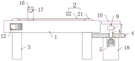
FIG. 1 is a front cross-sectional view of the present invention;
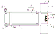
FIG. 2 is a top view of the present invention;
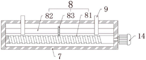
FIG. 3 is a side cross-sectional view of the web of the present invention;
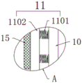
fig. 4 is an enlarged view of the structure of part a of fig. 2 according to the present invention.
In the figure: 1. a base; 2. a transport mechanism; 21. a conveying roller; 22. a conveyor belt; 3. a support plate; 4. a transverse plate; 5. a first motor; 6. a connecting rod; 7. a connecting plate; 8. an adjustment mechanism; 81. a worm; 82. rotating the rod; 83. a worm gear; 9. connecting blocks; 10. a material collecting frame; 11. a protection mechanism; 1101. a spring; 1102. a baffle plate; 12. a controller; 13. a second motor; 14. a third motor; 15. a rubber pad; 16. a U-shaped frame; 17. a camera; 18. a blanking plate; 19. and a limiting plate.
Detailed Description
The technical solutions in the embodiments of the present invention will be clearly and completely described below with reference to the drawings in the embodiments of the present invention, and it is obvious that the described embodiments are only a part of the embodiments of the present invention, and not all of the embodiments. All other embodiments, which can be derived by a person skilled in the art from the embodiments given herein without making any creative effort, shall fall within the protection scope of the present invention.
Referring to fig. 1-4, the present invention provides a technical solution: a sorting mechanism of a piston screen printing machine comprises a base 1, wherein a groove is formed in the upper portion of the base 1, a conveying mechanism 2 is arranged in the groove, supporting plates 3 are arranged on the left side and the right side of the bottom of the base 1, a transverse plate 4 is arranged on one side of the right supporting plate 3, a first motor 5 is arranged at the bottom of the transverse plate 4, a connecting rod 6 is arranged on an output shaft of the first motor 5, the top end of the connecting rod 6 penetrates through the transverse plate 4 and is provided with a connecting plate 7, a cavity is formed in the connecting plate 7, an adjusting mechanism 8 is arranged in the cavity, a plurality of connecting blocks 9 are arranged on the adjusting mechanism 8, the upper portions of the two connecting blocks 9 are provided with the same material collecting frame 10, a protecting mechanism 11 is arranged on the right side of the inside of the material collecting frame 10, a controller 12 is arranged on the left side of the front face of the base 1, and the first motor 5 is electrically connected with the controller 12;
the conveying mechanism 2 comprises two conveying rollers 21 and a conveying belt 22, the two conveying rollers 21 are rotatably installed in the groove, the conveying belt 22 is installed between the two conveying rollers 21, a second motor 13 is installed on the left side of the back of the base 1, an output shaft of the second motor 13 is connected with one end of the conveying roller 21 on the left side, the second motor 13 is electrically connected with the controller 12, the adjusting mechanism 8 comprises a worm 81, a rotating rod 82 and a worm wheel 83, the worm 81 is rotatably installed in the cavity, the rotating rod 82 is rotatably installed at the upper end of the worm 81 in the cavity, the worm wheel 83 is installed on the rotating rod 82, the worm wheel 83 is meshed with the worm 81, the connecting block 9 is installed on the rotating rod 82, a third motor 14 is installed on the back of the connecting plate 7, an output shaft of the third motor 14 is connected with one end of the worm 81, the third motor 14 is electrically connected with the controller 12, the protecting mechanism 11 comprises a plurality of springs 1101 and a baffle 1102, a plurality of springs 1101 are all installed on the right side inner wall of the collecting frame 10, the baffle 1102 is installed at one end, far away from the inner wall of the collecting frame 10, of the plurality of springs 1101, a rubber pad 15 is arranged at one end, far away from the spring 1101, of the baffle 1102, a U-shaped frame 16 is installed on the left side of the upper portion of the base 1, a camera 17 is installed on the top end of the inner side of the U-shaped frame 16, the camera 17 is electrically connected with the controller 12, the blanking plate 18 is installed on the front side and the rear side of the transverse plate 4, and the limiting plates 19 are installed on the left side and the right side of the upper portion of the blanking plate 18.
The working principle is as follows: when the utility model is used, firstly, the second motor 13 is driven to work by the controller 12, the second motor 13 drives the conveyer belt 22 to rotate by the conveyer roller 21, then the printed product falls on the conveyer belt 22, when the product passes through the U-shaped frame 16, whether the printed product is qualified is detected by the camera 17, then the printed product continuously moves by the conveyer belt 22 and falls into the collecting frame 10, the printed product can be prevented from being damaged due to collision by the spring 1101 and the baffle 1102, when the printed product is qualified, the first motor 5 is driven to work by the controller 12, the first motor 5 drives the collecting frame 10 to rotate clockwise by the connecting rod 6, so that the printed product is transferred to the lower plate 18 at the rear side, when the printed product is unqualified, the first motor 5 drives the collecting frame 10 to rotate anticlockwise by the connecting rod 6, so that the printed product is transferred to the lower plate 18 at the front side, and then can classify the unloading to certified products and defective work, realize the letter sorting to the printed matter to when unloading the printed matter, make the work of third motor 14 through controller 12, the work of third motor 14 drives dwang 82 through worm 81 and worm wheel 83 and rotates, and dwang 82 rotates and drives the slope of collecting frame 10, thereby be convenient for make the printed matter fall down on flitch 18, thereby improved work efficiency. When the automatic blanking device is used, qualified and unqualified printed matters can be sorted and blanked, the printed matters can be protected to a certain extent during sorting, the blanking of the printed matters is facilitated, and the working efficiency and the practicability of the device are greatly improved.
It is noted that, herein, relational terms such as first and second, and the like may be used solely to distinguish one entity or action from another entity or action without necessarily requiring or implying any actual such relationship or order between such entities or actions. Also, the terms "comprises," "comprising," or any other variation thereof, are intended to cover a non-exclusive inclusion, such that a process, method, article, or apparatus that comprises a list of elements does not include only those elements but may include other elements not expressly listed or inherent to such process, method, article, or apparatus.
Although embodiments of the present invention have been shown and described, it will be appreciated by those skilled in the art that changes, modifications, substitutions and alterations can be made in these embodiments without departing from the principles and spirit of the utility model, the scope of which is defined in the appended claims and their equivalents.
Claims (6)
1. The utility model provides a piston screen printing machine letter sorting mechanism, includes base (1), its characterized in that: the feeding device is characterized in that a groove is formed in the upper portion of the base (1), a conveying mechanism (2) is arranged in the groove, supporting plates (3) are arranged on the left side and the right side of the bottom of the base (1), a transverse plate (4) is arranged on one side of the supporting plate (3) on the right side, a first motor (5) is arranged at the bottom of the transverse plate (4), a connecting rod (6) is arranged on an output shaft of the first motor (5), the top end of the connecting rod (6) penetrates through the transverse plate (4) and is provided with a connecting plate (7), a cavity is formed in the connecting plate (7), an adjusting mechanism (8) is arranged in the cavity, a plurality of connecting blocks (9) are arranged on the adjusting mechanism (8), the same collecting frame (10) is arranged on the upper portions of the two connecting blocks (9), and a protection mechanism (11) is arranged on the right side of the inner portion of the collecting frame (10), the front left side of base (1) is provided with controller (12), first motor (5) and controller (12) electric connection.
2. The piston screen printing machine sorting mechanism of claim 1, wherein: transport mechanism (2) include two transfer rollers (21) and conveyer belt (22), two equal rotation of transfer roller (21) is installed in the recess, install between two transfer rollers (21) conveyer belt (22), second motor (13) are installed in the back left side of base (1), the output shaft of second motor (13) is connected with the one end of left side transfer roller (21), second motor (13) and controller (12) electric connection.
3. The piston screen printing machine sorting mechanism of claim 1, wherein: adjustment mechanism (8) are including worm (81), dwang (82), worm wheel (83), worm (81) are rotated and are installed in the cavity, dwang (82) are rotated and are installed the upper end at worm (81) in the cavity, install on dwang (82) worm wheel (83), just worm wheel (83) and worm (81) meshing, install on dwang (82) connecting block (9), third motor (14) are installed at the back of connecting plate (7), the output shaft of third motor (14) is connected with the one end of worm (81), third motor (14) and controller (12) electric connection.
4. The piston screen printing machine sorting mechanism of claim 1, wherein: the protection mechanism (11) comprises a plurality of springs (1101) and a baffle (1102), the springs (1101) are installed on the inner wall of the right side of the collecting frame (10), the baffle (1102) is installed at one end, away from the inner wall of the collecting frame (10), of the springs (1101), and a rubber pad (15) is arranged at one end, away from the springs (1101), of the baffle (1102).
5. The piston screen printing machine sorting mechanism of claim 1, wherein: u-shaped frame (16) are installed on the upper portion left side of base (1), camera (17) are installed on the inboard top of U-shaped frame (16), camera (17) and controller (12) electric connection.
6. The piston screen printing machine sorting mechanism of claim 1, wherein: flitch (18) down are all installed to both sides around diaphragm (4), just limiting plate (19) are all installed to the upper portion left and right sides of flitch (18) down.
Priority Applications (1)
| Application Number | Priority Date | Filing Date | Title |
|---|---|---|---|
| CN202121897166.XU CN215744900U (en) | 2021-08-13 | 2021-08-13 | Sorting mechanism of piston screen printing machine |
Applications Claiming Priority (1)
| Application Number | Priority Date | Filing Date | Title |
|---|---|---|---|
| CN202121897166.XU CN215744900U (en) | 2021-08-13 | 2021-08-13 | Sorting mechanism of piston screen printing machine |
Publications (1)
| Publication Number | Publication Date |
|---|---|
| CN215744900U true CN215744900U (en) | 2022-02-08 |
Family
ID=80074291
Family Applications (1)
| Application Number | Title | Priority Date | Filing Date |
|---|---|---|---|
| CN202121897166.XU Expired - Fee Related CN215744900U (en) | 2021-08-13 | 2021-08-13 | Sorting mechanism of piston screen printing machine |
Country Status (1)
| Country | Link |
|---|---|
| CN (1) | CN215744900U (en) |
Cited By (2)
| Publication number | Priority date | Publication date | Assignee | Title |
|---|---|---|---|---|
| CN114887929A (en) * | 2022-05-25 | 2022-08-12 | 深圳市至臻精密股份有限公司 | Adjustable conveying device of screen printing machine |
| CN118106227A (en) * | 2024-02-26 | 2024-05-31 | 华磊(嘉兴)智能科技有限公司 | Four-glass disc type visual inspection equipment |
-
2021
- 2021-08-13 CN CN202121897166.XU patent/CN215744900U/en not_active Expired - Fee Related
Cited By (3)
| Publication number | Priority date | Publication date | Assignee | Title |
|---|---|---|---|---|
| CN114887929A (en) * | 2022-05-25 | 2022-08-12 | 深圳市至臻精密股份有限公司 | Adjustable conveying device of screen printing machine |
| CN114887929B (en) * | 2022-05-25 | 2023-11-21 | 深圳市至臻精密股份有限公司 | Adjustable conveying device of screen printer |
| CN118106227A (en) * | 2024-02-26 | 2024-05-31 | 华磊(嘉兴)智能科技有限公司 | Four-glass disc type visual inspection equipment |
Similar Documents
| Publication | Publication Date | Title |
|---|---|---|
| CN215744900U (en) | Sorting mechanism of piston screen printing machine | |
| CN209214523U (en) | A kind of novel pasting board detection device | |
| CN113310950B (en) | Glass quality detection device | |
| CN215317747U (en) | A device for grinding the surface of graphite products | |
| CN210847254U (en) | A material sorting conveyor line | |
| CN108248935A (en) | Axial diode detects automatically, prints and mounted box all-in-one machine | |
| CN215613332U (en) | Automatic sorting and conveying device for electric control boards | |
| CN216685971U (en) | An automatic equipment for feeding | |
| CN114644210B (en) | Stacking equipment for processing bagged cement | |
| CN210882880U (en) | Anti-deviation conveying assembly for automatic packaging equipment | |
| CN210594146U (en) | Paper tube distributing and conveying device | |
| CN216323435U (en) | Material sorting device based on PLC control | |
| CN219949998U (en) | Paper feeder working in cooperation with printing wheel | |
| CN212291858U (en) | Conveying device | |
| CN116990230A (en) | Stamping part defect detection process and device based on machine vision | |
| CN216547103U (en) | Image processing detects and overflows material package system | |
| CN213534183U (en) | Convenient-to-feed ink-wash printing machine for paper packaging | |
| CN211891062U (en) | Printing cross cutting anti-sticking paper products device | |
| CN219839106U (en) | Conveyor with automatic carton arranging function | |
| CN221212743U (en) | Bubble-proof film laminating machine capable of automatically packaging | |
| CN222202016U (en) | A dust removal device for a photovoltaic solar cell screen printing machine | |
| CN216548687U (en) | A printed product inspection machine that prevents paper deformation | |
| CN218726558U (en) | Display screen detection device with automatic loading and unloading functions | |
| CN222409675U (en) | Rotary parts feeding device | |
| CN224014002U (en) | Full-automatic packaging machine for small hardware stamping parts |
Legal Events
| Date | Code | Title | Description |
|---|---|---|---|
| GR01 | Patent grant | ||
| GR01 | Patent grant | ||
| CF01 | Termination of patent right due to non-payment of annual fee | ||
| CF01 | Termination of patent right due to non-payment of annual fee |
Granted publication date: 20220208 |