CN215719436U - Constant pressure water supply pump - Google Patents
Constant pressure water supply pump Download PDFInfo
- Publication number
- CN215719436U CN215719436U CN202122030778.5U CN202122030778U CN215719436U CN 215719436 U CN215719436 U CN 215719436U CN 202122030778 U CN202122030778 U CN 202122030778U CN 215719436 U CN215719436 U CN 215719436U
- Authority
- CN
- China
- Prior art keywords
- pump body
- pump
- concave box
- constant pressure
- water supply
- Prior art date
- Legal status (The legal status is an assumption and is not a legal conclusion. Google has not performed a legal analysis and makes no representation as to the accuracy of the status listed.)
- Active
Links
Images


Abstract
The utility model relates to a constant-pressure water supply pump, which belongs to the technical field of water pumps and comprises a pump body, wherein a concave box is arranged at the upper end of the pump body, a stirring paddle and a penetration plate are respectively arranged at the upper side and the lower side inside the concave box, and the left end and the right end of the penetration plate are respectively spliced with the left end and the right end inside the concave box; the stirring rake has avoided the precipitate of aquatic to pile up in the infiltration board upper end and cause the jam, the infiltration board comes the precipitate filtration of aquatic, the infiltration board has reduced inside the precipitate enters into the pump body from concave box, the brush cleans the internal wall of pump along with the blade rotation, magnet can be convenient for clean the metal particles that gets off with the brush and give the absorption, the doctor-bar can stir rivers and clean the screen panel surface simultaneously, the doctor-bar has avoided the precipitate to pile up on the screen panel surface and has caused the jam, the incrustation scale has been piled up easily to current constant voltage working pump has been solved, and the inside problem of clearing up of water pump not be convenient for.
Description
Technical Field
The utility model relates to a constant-pressure water supply pump, and belongs to the technical field of water pumps.
Background
The water pump is a machine for conveying liquid or pressurizing liquid, and it can transfer the mechanical energy of prime mover or other external energy to the liquid to increase the energy of liquid, and is mainly used for conveying liquid including water, oil, acid-base liquid, emulsion, suspoemulsion and liquid metal, etc. The water pump can continuously supply water to the building, and with the continuous increase of high-rise buildings, the water supply pressure of high-rise users becomes a main problem of water supply companies, so that the constant pressure of the water pump becomes a difficult problem of main technical attack, and the water pump with good pressure becomes one of necessary conditions of constant pressure.
At present, the water pump is drawing water the in-process, and the precipitate of aquatic can be piled up inside the water pump along with rivers, and the inside certain metal particle that contains of precipitate, and accumulational precipitate forms the incrustation scale to also the not convenient to detach water pump comes to clear up its inside, causes certain damage to the water pump easily.
SUMMERY OF THE UTILITY MODEL
The utility model aims to overcome the defects of the prior art and provides a constant-pressure water supply pump, which solves the problems that the existing constant-pressure water supply pump is easy to accumulate scale and inconvenient to clean the interior of the water pump.
The technical scheme adopted by the utility model for solving the technical problems is as follows: a constant pressure water supply pump comprises a pump body;
the upper end of the pump body is provided with a concave box, the upper side and the lower side of the interior of the concave box are respectively provided with a stirring paddle and a penetration plate, and the left end and the right end of the penetration plate are respectively spliced with the left end and the right end of the interior of the concave box;
a square rod is arranged in the pump body, a round rod and a transmission shaft are respectively inserted into the left end and the right end of the square rod, a plurality of blades which are arranged in an annular mode are welded on the outer surface of the square rod, a connecting strip is fixed between the two adjacent blades on the left and the right, the outer end of each connecting strip is connected with a hairbrush through a screw, and the outer surface of each hairbrush is connected with a magnet through a screw;
the left end of the pump body is inserted with a side cover, a mesh enclosure positioned in the side cover is sleeved outside the round rod, the upper end and the lower end of the mesh enclosure are respectively inserted with the upper end and the lower end in the side cover, and at least two scraping blades which are annularly arranged are connected outside the round rod and positioned on the left side and the right side of the mesh enclosure through bolts.
As preferred, concave box upper end just is located the stirring rake top and is provided with the top cap, top cap upper end mid-mounting has motor two, there is the oral siphon top cap upper end left side through flange joint, concave box communicates with each other with oral siphon and pump body inside respectively, the stirring rake upper end runs through the top cap upper end and is connected with two power take off of motor.
Preferably, the right end of the pump body is provided with a first motor, and the right end of the transmission shaft penetrates through the right end of the pump body and is connected with the power output end of the first motor.
Preferably, a water outlet is formed in the left end of the side cover and communicated with the inside of the side cover, a pair of lock catches which are vertically distributed are mounted at the front end and the rear end between the pump body and the side cover, and a sealing ring is mounted at the joint between the pump body and the side cover.
Preferably, the inner side of the scraping blade is in close contact with the outer side of the mesh enclosure, and the outer part of the round rod is rotatably connected with the middle part of the mesh enclosure.
Preferably, the tail end of the brush is in close contact with the inner wall of the pump body.
Compared with the prior art, the utility model has the following beneficial effects:
the second motor drives the stirring paddle to rotate in the concave box to stir water in the concave box, the stirring paddle prevents sediment in the water from being accumulated at the upper end of the penetration plate to cause blockage, the sediment in the water is filtered through the penetration plate, and the penetration plate reduces the sediment from entering the pump body from the concave box;
first drive transmission shaft, square bar and the rotation of round bar respectively of motor to drive blade and doctor-bar respectively and rotate, the brush cleans the internal wall of pump along with the blade rotation, and magnet can be given the absorption with the metal particle thing that the brush cleaned off, and the doctor-bar can stir rivers and clean the screen panel surface simultaneously, and the doctor-bar has avoided the precipitate to pile up on the screen panel surface and causes the jam.
Drawings
FIG. 1 is a schematic view of the overall internal structure of the present invention;
FIG. 2 is a schematic view of the overall external structure of the present invention;
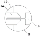
FIG. 3 is a left side view of the internal structure of the pump body of the present invention;
FIG. 4 is an enlarged view of a portion of structure A of the present invention;
FIG. 5 is an enlarged view of a portion of structure B of the present invention;
fig. 6 is a partially enlarged view of structure C of the present invention.
In the figure: 1-pump body, 2-side cover, 3-motor I, 4-motor II, 5-water inlet pipe, 6-top cover, 7-concave box, 8-brush, 9-magnet, 10-lock catch, 11-osmotic plate, 12-blade, 13-square bar, 14-transmission shaft, 15-round bar, 16-connecting bar, 17-screen cover, 18-scraping piece, 19-stirring paddle and 20-water outlet.
Detailed Description
Referring to fig. 1-6, the present invention provides a technical solution: a constant pressure water supply pump comprises a pump body 1;
the upper end of the pump body 1 is provided with a concave box 7, the upper side and the lower side of the interior of the concave box 7 are respectively provided with a stirring paddle 19 and a penetration plate 11, and the left end and the right end of the penetration plate 11 are respectively spliced with the left end and the right end of the interior of the concave box 7;
a square rod 13 is arranged inside the pump body 1, a round rod 15 and a transmission shaft 14 are respectively inserted at the left end and the right end of the square rod 13, a plurality of blades 12 which are arranged in an annular shape are welded on the outer surface of the square rod 13, a connecting strip 16 is fixed between the two adjacent blades 12 on the left and the right, the outer end of each connecting strip 16 is connected with a brush 8 through a screw, and the outer surface of each brush 8 is connected with a magnet 9 through a screw;
the left end of the pump body 1 is inserted with the side cover 2, the outer part of the round rod 15 is sleeved with a mesh enclosure 17 positioned in the side cover 2, the upper end and the lower end of the mesh enclosure 17 are respectively inserted with the upper end and the lower end in the side cover 2, and the outer part of the round rod 15 and the left and right sides of the mesh enclosure 17 are connected with at least two scraping blades 18 which are arranged in an annular shape through bolts;
a top cover 6 is arranged at the upper end of the concave box 7 and above the stirring paddle 19, a motor II 4 is arranged in the middle of the upper end of the top cover 6, the left side of the upper end of the top cover 6 is connected with the water inlet pipe 5 through a flange, the concave box 7 is respectively communicated with the water inlet pipe 5 and the interior of the pump body 1, the upper end of the stirring paddle 19 penetrates through the upper end of the top cover 6 and is connected with the power output end of the motor II 4, the motor II 4 drives the stirring paddle 19 to rotate in the concave box 7, water enters the concave box 7 from the water inlet pipe 5, so that the stirring paddle 19 stirs the water in the concave box 7, the stirring paddle 19 prevents sediment in the water from accumulating at the upper end of the penetration plate 11 to cause blockage, the sediment in the water is filtered through the penetration plate 11, then the penetration plate 11 reduces the sediment from entering the interior of the pump body 1 from the concave box 7, and the top cover 6 is opened so as to clean the accumulated sediment in the concave box 7;
water gradually enters the pump body 1 from the concave box 7, the motor I3 is installed at the right end of the pump body 1, the right end of the transmission shaft 14 penetrates through the right end of the pump body 1 and is connected with the power output end of the motor I3, the motor I3 is started to sequentially drive the transmission shaft 14, the square rod 13 and the round rod 15 to rotate, the square rod 13 drives the blades 12 to rotate, the blades 12 drive the connecting strips 16 to rotate around the square rod 13, the tail end of the hairbrush 8 is in close contact with the inner wall of the pump body 1, the hairbrush 8 rotates along with the blades 12, the blades 12 can pump the water on the one hand, the blades 12 can stir the water in the pump body 1 on the other hand, the hairbrush 8 cleans the inner wall of the pump body 1, the magnet 9 can adsorb metal particles cleaned by the hairbrush 8, the pollution of the metal particles to a water source is avoided, the inner side of the blade 18 is in close contact with the outer side of the mesh enclosure 17, the outer portion of the round rod 15 is rotatably connected with the middle of the mesh enclosure 17, the round rod 15 drives the scraping blade 18 to rotate, meanwhile, the scraping blade 18 can stir water flow and clean the surface of the mesh enclosure 17, the scraping blade 18 prevents sediment from accumulating on the surface of the mesh enclosure 17 to cause blockage, the left end of the side cover 2 is provided with a water outlet 20, the water outlet 20 is communicated with the inside of the side cover 2, and water source conveying can be carried out through the water outlet 20;
a pair of hasp 10 that is distribution from top to bottom is all installed at both ends around between the pump body 1 and the side cap 2, the sealing washer is installed to the junction between the pump body 1 and the side cap 2, can make between the side cap 2 and the pump body 1 two more inseparable through the sealing washer, open hasp 10 and can separate the pump body 1 with side cap 2, thereby take off side cap 2 and separate round bar 15 and square bar 13, thereby accessible screwdriver is with doctor-bar 18 follow round bar 15 surface dismantlement wash screen panel 17 or change, and pulling square bar 13 and with square bar 13 and transmission shaft 14 separation, so that pull down blade 12, can be to blade 12, magnet 9 and brush 8 wash, brush 8 is removable simultaneously, thereby be convenient for clear up side cap 2 inside, reduced the precipitate and piled up in pump body 1 is inside, be favorable to prolonging the life of the pump body 1.
Claims (6)
1. The utility model provides a constant pressure feed water pump, includes the pump body (1), its characterized in that:
a concave box (7) is mounted at the upper end of the pump body (1), a stirring paddle (19) and a penetration plate (11) are respectively arranged on the upper side and the lower side of the interior of the concave box (7), and the left end and the right end of the penetration plate (11) are respectively spliced with the left end and the right end of the interior of the concave box (7);
a square rod (13) is arranged inside the pump body (1), a round rod (15) and a transmission shaft (14) are respectively inserted at the left end and the right end of the square rod (13), a plurality of blades (12) which are arranged in an annular shape are welded on the outer surface of the square rod (13), a connecting strip (16) is fixed between each two adjacent blades (12) on the left side and the right side, the outer end of each connecting strip (16) is connected with a hairbrush (8) through a screw, and the outer surface of each hairbrush (8) is connected with a magnet (9) through a screw;
the left end of the pump body (1) is connected with the side cover (2) in an inserting mode, the outer portion of the round rod (15) is sleeved with the mesh enclosure (17) located inside the side cover (2), the upper end and the lower end of the mesh enclosure (17) are connected with the upper end and the lower end of the inner portion of the side cover (2) in an inserting mode respectively, and the outer portion of the round rod (15) located on the left side and the right side of the mesh enclosure (17) is connected with at least two scraping blades (18) which are arranged in an annular mode through bolts.
2. The constant pressure water supply pump as claimed in claim 1, wherein: concave box (7) upper end just is located stirring rake (19) top and is provided with top cap (6), top cap (6) upper end mid-mounting has motor two (4), there is oral siphon (5) top cap (6) upper end left side through flange joint, concave box (7) communicate with each other with oral siphon (5) and pump body (1) inside respectively, stirring rake (19) upper end runs through out top cap (6) upper end and is connected with motor two (4) power take off end.
3. The constant pressure water supply pump as claimed in claim 1, wherein: the motor I (3) is installed at the right end of the pump body (1), and the right end of the transmission shaft (14) penetrates through the right end of the pump body (1) and is connected with the power output end of the motor I (3).
4. The constant pressure water supply pump as claimed in claim 1, wherein: the left end of the side cover (2) is provided with a water outlet (20), the water outlet (20) is communicated with the inside of the side cover (2), a pair of lock catches (10) which are distributed up and down are arranged at the front end and the rear end between the pump body (1) and the side cover (2), and a sealing ring is arranged at the joint between the pump body (1) and the side cover (2).
5. The constant pressure water supply pump as claimed in claim 1, wherein: the inner side of the scraping blade (18) is in close contact with the outer side of the mesh enclosure (17), and the outer part of the round rod (15) is rotatably connected with the middle part of the mesh enclosure (17).
6. The constant pressure water supply pump as claimed in claim 1, wherein: the tail end of the brush (8) is in close contact with the inner wall of the pump body (1).
Priority Applications (1)
| Application Number | Priority Date | Filing Date | Title |
|---|---|---|---|
| CN202122030778.5U CN215719436U (en) | 2021-08-26 | 2021-08-26 | Constant pressure water supply pump |
Applications Claiming Priority (1)
| Application Number | Priority Date | Filing Date | Title |
|---|---|---|---|
| CN202122030778.5U CN215719436U (en) | 2021-08-26 | 2021-08-26 | Constant pressure water supply pump |
Publications (1)
| Publication Number | Publication Date |
|---|---|
| CN215719436U true CN215719436U (en) | 2022-02-01 |
Family
ID=80007666
Family Applications (1)
| Application Number | Title | Priority Date | Filing Date |
|---|---|---|---|
| CN202122030778.5U Active CN215719436U (en) | 2021-08-26 | 2021-08-26 | Constant pressure water supply pump |
Country Status (1)
| Country | Link |
|---|---|
| CN (1) | CN215719436U (en) |
-
2021
- 2021-08-26 CN CN202122030778.5U patent/CN215719436U/en active Active
Similar Documents
| Publication | Publication Date | Title |
|---|---|---|
| CN215691959U (en) | Sewage discharging pipeline for river water pollution treatment | |
| CN215166421U (en) | Integration pump station is with preventing stifled pump system | |
| CN208121732U (en) | A kind of oil slick collecting device | |
| CN113250968B (en) | Siphon and electric pump water supply type water taking pump ship | |
| CN215719436U (en) | Constant pressure water supply pump | |
| CN112237785A (en) | Sludge cleaning device for sewage treatment tank | |
| CN210367197U (en) | Sewage treatment tank | |
| CN216236201U (en) | Energy-saving environment-friendly outdoor wastewater treatment device | |
| CN216755495U (en) | Mud scraper convenient to stirring | |
| CN213965308U (en) | Two heavy pond dross collection device that sink | |
| CN213572161U (en) | Integration pump station convenient to desilting | |
| CN213114490U (en) | A diversion structure that is used for convenient clearance of hydraulic and hydroelectric engineering | |
| CN211914861U (en) | Oil field pipeline safety ring protects cleaning device | |
| CN112923593A (en) | Geothermal tail water recharging system | |
| CN219848311U (en) | Automatic cleaning device for effluent weir of horizontal flow type secondary sedimentation tank of sewage treatment plant | |
| CN215514049U (en) | Automatic salvage ship for garbage in water area | |
| CN219932569U (en) | Automatic descaling water pump | |
| CN214533567U (en) | Novel place stable flowing back device | |
| CN218223798U (en) | Chemical production is with industrial chemicals rinsing device | |
| CN215049310U (en) | Sewage treatment device for municipal engineering construction | |
| CN218204274U (en) | River channel debris clearance ware for municipal works | |
| CN219355375U (en) | Sewage treatment case convenient to clearance | |
| CN213506253U (en) | Environment-friendly sewage treatment plant | |
| CN210206021U (en) | Sewage filtering device for water treatment | |
| CN212559796U (en) | Ultrasonic cleaning wastewater and sewage integrated treatment equipment |
Legal Events
| Date | Code | Title | Description |
|---|---|---|---|
| GR01 | Patent grant | ||
| GR01 | Patent grant |