CN215705469U - Material rack special for front wall plate beam assembly - Google Patents
Material rack special for front wall plate beam assembly Download PDFInfo
- Publication number
- CN215705469U CN215705469U CN202122190760.1U CN202122190760U CN215705469U CN 215705469 U CN215705469 U CN 215705469U CN 202122190760 U CN202122190760 U CN 202122190760U CN 215705469 U CN215705469 U CN 215705469U
- Authority
- CN
- China
- Prior art keywords
- outer frame
- roller
- base
- front wall
- beam assembly
- Prior art date
- Legal status (The legal status is an assumption and is not a legal conclusion. Google has not performed a legal analysis and makes no representation as to the accuracy of the status listed.)
- Active
Links
Images


Abstract
A special material rack for a front wall plate beam assembly relates to workshop storage equipment and comprises an outer frame, wherein four corners of the bottom of the outer frame are connected with a base, a plurality of single-layer workpiece frames are arranged in the outer frame, the front side of each single-layer workpiece frame is hinged with the outer frame, the left side and the right side of the outer frame are connected with gas spring mounting plates, and the left side and the right side of each single-layer workpiece frame are connected with the gas spring mounting plates through gas springs; the bottom of the outer frame is provided with two rotating shafts, one end of each rotating shaft is connected with the operating part, two ends of each rotating shaft are provided with a bearing and a bearing seat, and the four bearing seats are connected with the outer frame; each base is internally provided with a roller mechanism, the roller mechanism comprises a roller seat and a roller, and two support shafts are fixedly connected to the roller seat; two vertical holes are formed in each base, and the supporting shaft is arranged in each vertical hole; two ejector blocks are connected to each rotating shaft, each ejector block abuts against a corresponding roller seat, and the ejector blocks and the rotating shafts are arranged eccentrically. The utility model is convenient to use.
Description
Technical Field
The utility model relates to workshop storage equipment, in particular to a material rack for placing automobile parts.
Background
When welding assembly line job site, need place preceding bounding wall crossbeam assembly with work or material rest (all revolving racks), current work or material rest is simple and easy frame, connects the base respectively on four angles of frame bottom, sets up the fork inserted hole on the base. During the turnover, insert the fork inserted hole of fork truck's fork bottom, remove through fork truck. The existing material rack has the following defects: 1. get and put preceding bounding wall crossbeam assembly operation inconvenient. 2. After the front wall plate beam assembly is taken down, when the material rest needs to be moved, or when the material rest is moved in a short distance, the material rest is inconvenient because of no roller. 3. Stability is required during loading, but if the roller is installed, displacement is realized along with the increase of the front wall plate beam assembly; if promote the work or material rest during the turnover, cause the work or material rest to damage, warp, the work or material rest warp and easily leads to preceding bounding wall beam assembly to warp. Therefore, the material frame is not allowed to be pushed by the 'using management rule of the turnover frame', and the roller has no use value. Therefore, a material rack which is convenient to load and unload materials and allows the rollers to retract and extend according to requirements needs to be designed.
SUMMERY OF THE UTILITY MODEL
The utility model aims to overcome the defects of the prior art and provides a special material rack for a front wall plate and beam assembly, which is convenient to use.
The purpose of the utility model is realized as follows: a special material rack for a front wall plate beam assembly comprises an outer frame, wherein four corners of the bottom of the outer frame are respectively connected with a base, and a pallet fork insertion hole is formed in the base; the single-layer workpiece positioning device comprises an outer frame, a plurality of single-layer workpiece frames, air spring mounting plates, air springs, a plurality of positioning columns and a positioning device, wherein the single-layer workpiece frames are arranged in the outer frame from bottom to top in sequence; the bottom of the outer frame is provided with two rotating shafts, one end of each rotating shaft is connected with the operating part, two ends of each rotating shaft are provided with a bearing and a bearing seat, and the four bearing seats are connected with the outer frame; each base is internally provided with a roller mechanism, the roller mechanism comprises a roller seat and a roller, and two support shafts are fixedly connected to the roller seat; two vertical holes are formed in each base, and the supporting shaft is arranged in each vertical hole; two ejector blocks are connected to each rotating shaft, each ejector block abuts against a corresponding roller seat, the ejector blocks and the rotating shafts are arranged in an eccentric mode, the ejector blocks form a long shaft part and a short shaft part, and when the long shaft part abuts against the roller seats, the rollers extend out of the base; when the long shaft part leaves the roller seat, the roller retracts into the base.
When the material rack needs to be moved after unloading, the operating part is stepped by feet to drive the rotating shaft to rotate, the rotating shaft drives the ejector block to rotate, so that the long shaft part abuts against the roller seat, the outer frame moves upwards, namely the base moves upwards, the supporting shaft is arranged at the lower end of the vertical hole, the roller is exposed out of the base, and the material rack can be pushed. Before loading, the rotating shaft is driven to rotate through the operating part, the long shaft part of the ejector block leaves the roller seat, the outer frame moves downwards, namely the base moves downwards and is supported on the ground, and meanwhile, the supporting shaft is arranged at the upper end of the vertical hole. The utility model can use or hide the idler wheel according to the actual requirement, so that the material rack is more convenient to operate. When loading, the upper single-layer workpiece frames are opened upwards through the gas spring, and are leveled layer by layer after one layer is loaded.
For operating stability the bottom of outer frame sets up the locating hole, the operating portion includes dead lever and movable rod, and the one end and the pivot of dead lever are connected, and the movable rod wears the other end at the dead lever, and movable rod detachable sets up in the locating hole. When the long shaft part is against the roller seat, the movable rod of the operating part is inserted into the positioning hole.
In order to ensure that the roller can only move up and down and avoid moving in other directions, the two ends of the supporting shaft are provided with threads, and the two ends of the supporting shaft extend out of the base and then are connected with nuts.
And two guide rods are respectively arranged on each roller seat in a penetrating manner, are vertically arranged and are connected with the outer frame.
The top block of the utility model is circular.
The top block of the utility model is in a round corner rectangle shape.
Drawings
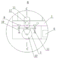
Fig. 1 is a first structural diagram of the present invention.
Fig. 2 is a view taken along direction a of fig. 1.
Fig. 3 is an enlarged view of a portion B in fig. 1.
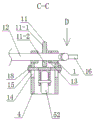
Fig. 4 is a view from direction C-C in fig. 3.
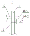
Fig. 5 is a view from direction D of fig. 4.
Fig. 6 is another schematic view of the top block.
Detailed Description
Example 1
As shown in fig. 1 to 5, the material rack special for the front wall plate beam assembly comprises an outer frame 1, wherein four corners of the bottom of the outer frame 1 are respectively connected with a base 4, and a fork insertion opening 6 is formed in the base 4. Five single-layer workpiece frames 2 are arranged in an outer frame 1, the five single-layer workpiece frames 2 are stacked in sequence from bottom to top, the front side of each single-layer workpiece frame 2 is hinged to the outer frame 1, the left side and the right side of the outer frame 1 are connected with air spring mounting plates 8, the left side and the right side of each single-layer workpiece frame 2 are hinged to air springs 7, the other end of each air spring 7 is hinged to the air spring mounting plates 8, and each single-layer workpiece frame 2 is connected with a plurality of positioning columns 3.
When loading, the four single-layer workpiece frames 2 are opened upwards through the gas spring 7, and after one layer is loaded, the workpiece frames are leveled layer by layer.
The bottom of the outer frame 1 is provided with two rotating shafts 12, one end of each rotating shaft 12 extends out of the outer frame 1 and is connected with an operating part 16, the bottom of the outer frame 1 is provided with a positioning hole 17, each operating part 16 comprises a fixed rod 16-1 and a movable rod 16-2, one end of each fixed rod 16-1 is connected with the corresponding rotating shaft 12, each movable rod 16-2 penetrates through the other end of the corresponding fixed rod 16-1, and each movable rod 16-2 is detachably arranged in the corresponding positioning hole 17. Two ends of each rotating shaft 12 are provided with a bearing and a bearing seat 13, and the four bearing seats 13 are connected with the outer frame 1.
Each base 4 is provided with a roller mechanism 5, the roller mechanism 5 comprises a roller seat 51 and a roller 52, the roller 52 can be a directional wheel or a universal wheel, and the two sides of the roller seat 51 are respectively fixedly connected with a support shaft 18. Two guide rods 9 penetrate through each roller seat 51 respectively, the guide rods 9 are vertically arranged, the lower ends of the guide rods 9 extend out of the roller seats 51, the upper ends of the guide rods 9 are connected with fixing blocks 10, and the fixing blocks 10 are connected with the outer frame 1. Two vertical holes 14 are formed in each base 4, a supporting shaft 18 is arranged in each vertical hole 14, threads are arranged at two ends of each supporting shaft 18, and nuts 15 are connected to two ends of each supporting shaft 18 after extending out of the bases 4.
Two top blocks 11 are connected to each rotating shaft 12, each top block 11 is in a round rectangle, each top block 11 is against a corresponding roller seat 51, the top blocks 11 and the rotating shafts 12 are arranged eccentrically, the top blocks 11 form a long shaft part 11-1 and a short shaft part 11-2, and when the long shaft part 11-1 is against the roller seat 51, the rollers 52 extend out of the base 4; when the long shaft part 11-1 leaves the roller seat 51, the roller 52 retracts into the base 4.
When the roller is needed, the operating part 16 is stepped by foot to drive the rotating shaft 12 to rotate, the rotating shaft 12 drives the top block 11 to rotate, so that the long shaft part 11-1 is pressed against the roller seat 51 to move the outer frame 1 upwards, namely the base 4 moves upwards, the supporting shaft 18 is arranged at the lower end of the vertical hole 14, the roller 52 is exposed out of the base 4, and the movable rod 16-2 can be inserted into the positioning hole 17.
When the roller needs to be hidden, the movable rod 16-2 is pulled out from the positioning hole 17, the operation part 16 drives the rotating shaft 12 to rotate, the long shaft part 11-1 of the top block 11 leaves the roller seat 51, the outer frame 1 moves downwards under the action of gravity, namely the base 4 moves downwards and is supported on the ground, and meanwhile, the support shaft 18 is arranged at the upper end of the vertical hole 14.
Example 2
As shown in fig. 6, the top block 11 is circular, and the rest of the structure is the same as that of embodiment 1.
Claims (6)
1. A special material rack for a front wall plate beam assembly comprises an outer frame, wherein four corners of the bottom of the outer frame are respectively connected with a base, and a pallet fork insertion hole is formed in the base; the method is characterized in that: the single-layer workpiece positioning device comprises an outer frame, a plurality of single-layer workpiece frames, air spring mounting plates, air springs, a plurality of positioning columns and a positioning device, wherein the single-layer workpiece frames are arranged in the outer frame from bottom to top in sequence; the bottom of the outer frame is provided with two rotating shafts, one end of each rotating shaft is connected with the operating part, two ends of each rotating shaft are provided with a bearing and a bearing seat, and the four bearing seats are connected with the outer frame; each base is internally provided with a roller mechanism, the roller mechanism comprises a roller seat and a roller, and two support shafts are fixedly connected to the roller seat; two vertical holes are formed in each base, and the supporting shaft is arranged in each vertical hole; two ejector blocks are connected to each rotating shaft, each ejector block abuts against a corresponding roller seat, the ejector blocks and the rotating shafts are arranged in an eccentric mode, the ejector blocks form a long shaft part and a short shaft part, and when the long shaft part abuts against the roller seats, the rollers extend out of the base; when the long shaft part leaves the roller seat, the roller retracts into the base.
2. The special material rack for the front wall panel beam assembly as claimed in claim 1, wherein: the bottom of outer frame sets up the locating hole, the operating portion includes dead lever and movable rod, and the one end and the pivot of dead lever are connected, and the movable rod wears the other end at the dead lever, and movable rod detachable sets up in the locating hole.
3. The special material rack for the front wall panel beam assembly as claimed in claim 1, wherein: the two ends of the supporting shaft are provided with threads, and the two ends of the supporting shaft extend out of the base and then are connected with nuts.
4. The special material rack for the front wall panel beam assembly as claimed in claim 1, wherein: two guide rods penetrate through each roller seat respectively, are vertically arranged and are connected with the outer frame.
5. The special material rack for the front wall panel beam assembly as claimed in claim 1, wherein: the top block is circular.
6. The special material rack for the front wall panel beam assembly as claimed in claim 1, wherein: the top block is in a round corner rectangle shape.
Priority Applications (1)
| Application Number | Priority Date | Filing Date | Title |
|---|---|---|---|
| CN202122190760.1U CN215705469U (en) | 2021-09-10 | 2021-09-10 | Material rack special for front wall plate beam assembly |
Applications Claiming Priority (1)
| Application Number | Priority Date | Filing Date | Title |
|---|---|---|---|
| CN202122190760.1U CN215705469U (en) | 2021-09-10 | 2021-09-10 | Material rack special for front wall plate beam assembly |
Publications (1)
| Publication Number | Publication Date |
|---|---|
| CN215705469U true CN215705469U (en) | 2022-02-01 |
Family
ID=80018433
Family Applications (1)
| Application Number | Title | Priority Date | Filing Date |
|---|---|---|---|
| CN202122190760.1U Active CN215705469U (en) | 2021-09-10 | 2021-09-10 | Material rack special for front wall plate beam assembly |
Country Status (1)
| Country | Link |
|---|---|
| CN (1) | CN215705469U (en) |
-
2021
- 2021-09-10 CN CN202122190760.1U patent/CN215705469U/en active Active
Similar Documents
| Publication | Publication Date | Title |
|---|---|---|
| CN215705469U (en) | Material rack special for front wall plate beam assembly | |
| CN111037519A (en) | Movable vibration exciter mounting machine | |
| CN105858199A (en) | Automatic feeding device on liquid crystal display panel bar breaking equipment and feeding method thereof | |
| CN212981311U (en) | Heavy-load micro-motion lifting device for stereoscopic warehouse piling car | |
| CN210677582U (en) | Turnover mechanism for automobile beam | |
| CN211278063U (en) | Spread material and unload mould ejecting integrative device | |
| CN217398362U (en) | Stacker for logistics storage | |
| CN214918343U (en) | Online positive recovery mechanism of medium density fiberboard waste board | |
| CN212830761U (en) | Integrated logistics goods shelf | |
| CN211100895U (en) | Goods shelf corrector | |
| CN217436931U (en) | Lifting platform for stacking plates | |
| CN212923378U (en) | Automatic blanking equipment for plastic film material roll | |
| CN220578077U (en) | Unloading storage mechanism of computer memory strip check out test set | |
| CN219906225U (en) | Unloading device for commodity wholesale | |
| CN220098491U (en) | Side turning machine | |
| CN220484309U (en) | Angle steel raw material jacking vertical warehouse | |
| CN220167242U (en) | Dry-hanging stone wall construction equipment | |
| CN217669275U (en) | Quick positioning mechanism of model tire | |
| CN215665954U (en) | Robot stacking device | |
| JP3367819B2 (en) | Drum crushing machine and drum crushing method | |
| CN211762645U (en) | Numerical control automatic brick cutter | |
| CN214568877U (en) | Board up-and-down conveying device | |
| CN217128098U (en) | Positioning jig frame for pre-embedded ribs of anti-collision guardrail | |
| CN215108957U (en) | A automatic storage device of top anchor net for roadway support | |
| CN210943791U (en) | Polaroid feeding device |
Legal Events
| Date | Code | Title | Description |
|---|---|---|---|
| GR01 | Patent grant | ||
| GR01 | Patent grant |