CN215701980U - Cutting device for plastic plate - Google Patents
Cutting device for plastic plate Download PDFInfo
- Publication number
- CN215701980U CN215701980U CN202120314425.5U CN202120314425U CN215701980U CN 215701980 U CN215701980 U CN 215701980U CN 202120314425 U CN202120314425 U CN 202120314425U CN 215701980 U CN215701980 U CN 215701980U
- Authority
- CN
- China
- Prior art keywords
- base
- motor
- cutting device
- riser
- fixedly connected
- Prior art date
- Legal status (The legal status is an assumption and is not a legal conclusion. Google has not performed a legal analysis and makes no representation as to the accuracy of the status listed.)
- Active
Links
Images

Landscapes
- Sawing (AREA)
Abstract
The utility model discloses a cutting device for a plastic plate, which comprises a base, riser and roof, the riser sets up in the top of base, the roof sets up in the top of riser, the base is provided with the recess, the base transversely is provided with first motor by the one end of riser, the output of first motor runs through the lateral wall of base and extends to in the recess, be provided with the screw thread post in the recess, screw thread post threaded connection has the slider, the top of slider is provided with clamping device, the output cover of first motor is equipped with first synchronous area, first synchronous belt drive is connected with from the driving wheel, base top middle section sets up cutting mechanism, the bottom of roof is provided with the telescopic link, the bottom of telescopic link is provided with the connecting block, the connecting block articulates there is the conveyer pipe, the one end of conveyer pipe is provided with the dust absorption mouth, the other end fixedly connected with fan of conveyer pipe, the dust absorption mouth sets up in cutting mechanism's top.
Description
Technical Field
The utility model relates to the technical field of plastic plate processing, in particular to a cutting device for a plastic plate.
Background
When the existing cutting device is used for cutting the plastic plate, because no clamping device is used for positioning the plastic plate, the plastic plate is positioned by hands of people, danger is brought to workers, and the plastic plate is easy to generate a large amount of chips to pollute the environment when being cut, so that the problem is solved, and the cutting device for the plastic plate is provided.
SUMMERY OF THE UTILITY MODEL
In order to solve the above problems, the present invention provides a cutting device for a plastic panel, comprising a base, riser and roof, the riser sets up in the top of base, the roof sets up in the top of riser, the base is provided with the recess, the base transversely is provided with first motor by the one end of riser, the output of first motor runs through the lateral wall of base and extends to in the recess, be provided with the screw thread post in the recess, screw thread post threaded connection has the slider, the top of slider is provided with clamping device, the output cover of first motor is equipped with first synchronous area, first synchronous belt drive is connected with from the driving wheel, base top middle section sets up cutting mechanism, the bottom of roof is provided with the telescopic link, the bottom of telescopic link is provided with the connecting block, the connecting block articulates there is the conveyer pipe, the one end of conveyer pipe is provided with the dust absorption mouth, the other end fixedly connected with fan of conveyer pipe, the dust absorption mouth sets up in cutting mechanism's top.
Further, cutting mechanism includes the cutter, cutter fixedly connected with pivot, and the below of pivot is provided with the second motor, and the output pot head of second motor is provided with the second hold-in range, and second hold-in range transmission is connected in the pivot.
Further, clamping device includes L type support, and L type support is provided with the recess, is provided with the threaded rod in the recess, and threaded rod threaded connection has the fly leaf, the top fixedly connected with nut of threaded rod.
Furthermore, one end of the fan penetrates through the vertical plate, and the fan is fixedly connected with a waste bin.
Further, the middle section of riser is provided with the fagging, fan fixed connection in fagging.
Furthermore, the bottom of the base is provided with supporting legs, and the bottom of the supporting legs is provided with a cushion pad.
The utility model has the following beneficial effects:
according to the utility model, the plastic plate is fixed through the clamping device, the first motor drives the sliding block to move on the threaded rod, the plastic plate is driven to pass through the cutting device, the plastic plate is cut, the danger of manually holding the plastic plate is avoided, the telescopic rod is adjusted, the dust suction port is controlled to be aligned with the cutting device, and the cut plastic scraps are collected, so that the working environment is protected, and the working pressure of subsequent cleaning is reduced.
Drawings
FIG. 1 is a schematic view showing a structure of a cutting apparatus for a plastic plate;
FIG. 2 is a side view of the base;
wherein the reference numerals are as follows: 1. a base; 2. a vertical plate; 3. a top plate; 4. a first motor; 5. a first synchronization belt; 6. a threaded post; 7. a cutting mechanism; 71. a cutter; 72. a rotating shaft; 73. a second synchronous belt; 74. a second motor; 8. a slider; 9. a clamping device; 91. an L-shaped support; 92. a threaded rod; 93. a movable plate; 94. a nut; 10. a dust suction port; 11. a telescopic rod; 12. connecting blocks; 13. a delivery pipe; 14. a fan; 15. a waste bin; 16. a supporting plate; 17. supporting legs; 18. a cushion pad; 19. a driven wheel.
Detailed Description
In the description of the present invention, it should be noted that the terms "center", "upper", "lower", "left", "right", "vertical", "horizontal", "inner", "outer", etc., indicate orientations or positional relationships based on the orientations or positional relationships shown in the drawings, and are only for convenience of description and simplicity of description, but do not indicate or imply that the device or element being referred to must have a particular orientation, be constructed and operated in a particular orientation, and thus, should not be construed as limiting the present invention. Furthermore, the terms "first," "second," and "third" are used for descriptive purposes only and are not to be construed as indicating or implying a relative importance.
In the description of the present invention, it should be noted that, unless otherwise explicitly specified or limited, the terms "mounted," "connected," and "connected" are to be construed broadly, e.g., as meaning either a fixed connection, a removable connection, or an integral connection; can be mechanically or electrically connected; they may be connected directly or indirectly through intervening media, or they may be interconnected between two elements. The specific meanings of the above terms in the present invention can be understood in specific cases to those skilled in the art.
Referring to fig. 1 to 2, a cutting device for a plastic plate comprises a base 1, a vertical plate 2 and a top plate 3, wherein the vertical plate 2 is arranged at the top of the base 1, the top plate 3 is arranged at the top of the vertical plate 2, the base 1 is provided with a groove, one end of the base 1 close to the vertical plate 2 is transversely provided with a first motor 4, the output end of the first motor 4 penetrates through the side wall of the base 1 and extends into the groove, a threaded column 6 is arranged in the groove, the threaded column 6 is in threaded connection with a sliding block 8, the top of the sliding block 8 is provided with a clamping device 9, the output end of the first motor is sleeved with a first synchronous belt 5, the first synchronous belt 5 is in transmission connection with a driven wheel 19, the middle section of the top of the base 1 is provided with a cutting mechanism 7, the bottom of the top plate 3 is provided with a telescopic rod 11, the bottom of the telescopic rod 11 is provided with a connecting block 12, the connecting block 12 is hinged with a conveying pipe 13, and one end of the conveying pipe 13 is provided with a dust suction port 10, the other end of the conveying pipe 13 is fixedly connected with a fan 14, and the dust suction port 10 is arranged above the cutting mechanism 7.
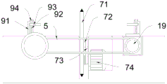
Wherein, cutting mechanism 7 includes cutter 71, cutter 71 fixedly connected with pivot 72, and the below of pivot 72 is provided with second motor 74, and the output pot head of second motor 74 is provided with second hold-in range 73, and second hold-in range 73 transmission is connected in pivot 72.
Wherein, clamping device 9 includes L type support 91, and L type support 91 is provided with the recess, is provided with threaded rod 92 in the recess, and threaded rod 92 threaded connection has fly leaf 93, and threaded rod 92's top fixedly connected with nut 94.
Wherein, the one end of fan 14 runs through riser 2, and fan 14 fixedly connected with dump bin 15 is used for collecting the plastics piece.
Wherein, the middle section of riser 2 is provided with fagging 16, and fan 14 fixed connection is in fagging 16.
Wherein, the bottom of base 1 is provided with supporting legs 17, and the bottom of supporting legs 17 is provided with blotter 18, reduces the vibration when doing work.
The working principle of the utility model is as follows: during the use, drive second motor 74, it is rotatory to drive cutter 71, place the plastic slab between two clamping device 9, adjust clamping device 9's nut 94, control fly leaf 93 moves down, press from both sides the plastic slab tightly, drive first motor 4 and drive the hold-in range work, drive threaded rod 92 corotation, make slider 8 translate toward cutter 71, thereby make the plastic slab also translate toward cutter 71 mechanism, drive telescopic link 11 descends, adjust dust absorption mouth 10 to a suitable height and aim at cutter 71 mechanism, drive fan 14 does the work and produces suction, when cutting mechanism 7 cuts the plastic slab, the plastics piece is collected via dust absorption mouth 10, via conveyer pipe 13 again, inhale to dump bin 15 and collect.
The foregoing illustrates and describes the principles, general features, and advantages of the present invention. It will be understood by those skilled in the art that the present invention is not limited to the embodiments described above, which are described in the specification and illustrated only to illustrate the principle of the present invention, but that various changes and modifications may be made therein without departing from the spirit and scope of the present invention, which fall within the scope of the utility model as claimed.
Claims (6)
1. The utility model provides a cutting device for plastic slab, includes base (1), riser (2) and roof (3), riser (2) set up in the top of base (1), roof (3) set up in the top of riser (2), its characterized in that: the base (1) is provided with a groove, one end of the base (1) close to a vertical plate (2) is transversely provided with a first motor (4), the output end of the first motor (4) penetrates through the side wall of the base (1) and extends into the groove, a threaded column (6) is arranged in the groove, the threaded column (6) is in threaded connection with a sliding block (8), the top of the sliding block (8) is provided with a clamping device (9), the output end of the first motor is sleeved with a first synchronous belt (5), the first synchronous belt (5) is in transmission connection with a driven wheel (19), the middle section of the top of the base (1) is provided with a cutting mechanism (7), the bottom of the top plate (3) is provided with a telescopic rod (11), the bottom of the telescopic rod (11) is provided with a connecting block (12), the connecting block (12) is hinged with a conveying pipe (13), one end of the conveying pipe (13) is provided with a dust suction port (10), the other end fixedly connected with fan (14) of conveyer pipe (13), dust absorption mouth (10) set up in the top of cutting mechanism (7).
2. A cutting device for plastic sheets according to claim 1, wherein: cutting mechanism (7) include cutter (71), cutter (71) fixedly connected with pivot (72), the below of pivot (72) is provided with second motor (74), the output pot head of second motor (74) is provided with second hold-in range (73), second hold-in range (73) transmission connect in pivot (72).
3. A cutting device for plastic sheets according to claim 1, wherein: clamping device (9) are including L type support (91), L type support (91) are provided with the recess, be provided with threaded rod (92) in the recess, threaded rod (92) threaded connection has fly leaf (93), the top fixedly connected with nut (94) of threaded rod (92).
4. A cutting device for plastic sheets according to claim 1, wherein: one end of the fan (14) penetrates through the vertical plate (2), and the fan (14) is fixedly connected with a waste box (15).
5. A cutting device for plastic sheets according to claim 1, wherein: the middle section of the vertical plate (2) is provided with a supporting plate (16), and the fan (14) is fixedly connected to the supporting plate (16).
6. A cutting device for plastic sheets according to claim 1, wherein: the bottom of base (1) is provided with supporting legs (17), the bottom of supporting legs (17) is provided with blotter (18).
Priority Applications (1)
| Application Number | Priority Date | Filing Date | Title |
|---|---|---|---|
| CN202120314425.5U CN215701980U (en) | 2021-02-04 | 2021-02-04 | Cutting device for plastic plate |
Applications Claiming Priority (1)
| Application Number | Priority Date | Filing Date | Title |
|---|---|---|---|
| CN202120314425.5U CN215701980U (en) | 2021-02-04 | 2021-02-04 | Cutting device for plastic plate |
Publications (1)
| Publication Number | Publication Date |
|---|---|
| CN215701980U true CN215701980U (en) | 2022-02-01 |
Family
ID=80012113
Family Applications (1)
| Application Number | Title | Priority Date | Filing Date |
|---|---|---|---|
| CN202120314425.5U Active CN215701980U (en) | 2021-02-04 | 2021-02-04 | Cutting device for plastic plate |
Country Status (1)
| Country | Link |
|---|---|
| CN (1) | CN215701980U (en) |
-
2021
- 2021-02-04 CN CN202120314425.5U patent/CN215701980U/en active Active
Similar Documents
| Publication | Publication Date | Title |
|---|---|---|
| CN214724978U (en) | Automatic chip removal device of furniture board multi-angle cutting | |
| CN110370343A (en) | A kind of filter cloth positioning cutting means | |
| CN114799310A (en) | Plate shearing machine with intelligence chip removal structure | |
| CN211278776U (en) | Cutting mechanism is used in processing of wooden door convenient to adjust | |
| CN215787057U (en) | Multifunctional plate shearing machine convenient to adjust | |
| CN205870745U (en) | A equipment for automatic cutout panel | |
| CN207747643U (en) | A kind of wood-worker engraving machine | |
| CN215701980U (en) | Cutting device for plastic plate | |
| CN113844097B (en) | Plastic bag production is with cutting device that has a function of collecting broken bits | |
| CN215702357U (en) | Plate corner cutting machine | |
| CN211053237U (en) | Accurate high cleanliness's panel beating numerically controlled fraise machine | |
| CN210968208U (en) | Polishing edge banding machine for furniture production and processing | |
| CN208800921U (en) | A kind of laser cutter pipe-supporting mechanism | |
| CN219276796U (en) | Corrugated paper cutting device for carton production | |
| CN215749638U (en) | Environment-friendly foam board cutting machine | |
| CN213499769U (en) | Fixing auxiliary device of cutting machine for furniture processing | |
| CN214815021U (en) | Compressor bottom plate drilling equipment | |
| CN221754914U (en) | Hydraulic angle steel corner cutting machine | |
| CN219402572U (en) | Automatic chip-removing plate cutting device | |
| CN221185128U (en) | Flange gasket cutting tool | |
| CN219505526U (en) | Cutting mechanism for carton packaging production | |
| CN220462435U (en) | Quick loading attachment of longmen scissors | |
| CN221496454U (en) | Easily-used cutting machine | |
| CN213318056U (en) | Quick unloader is used to circular saw | |
| CN214179270U (en) | Automatic shearing device for nose bridge strip of mask |
Legal Events
| Date | Code | Title | Description |
|---|---|---|---|
| GR01 | Patent grant | ||
| GR01 | Patent grant |