CN215698235U - Portable removal bore hole equipment of electric drive - Google Patents
Portable removal bore hole equipment of electric drive Download PDFInfo
- Publication number
- CN215698235U CN215698235U CN202122442501.3U CN202122442501U CN215698235U CN 215698235 U CN215698235 U CN 215698235U CN 202122442501 U CN202122442501 U CN 202122442501U CN 215698235 U CN215698235 U CN 215698235U
- Authority
- CN
- China
- Prior art keywords
- screw rod
- way
- fixedly connected
- boring
- driving motor
- Prior art date
- Legal status (The legal status is an assumption and is not a legal conclusion. Google has not performed a legal analysis and makes no representation as to the accuracy of the status listed.)
- Active
Links
Images


Abstract
The utility model is suitable for the technical field of boring equipment, and provides an electric-driven portable movable boring equipment, which comprises an equipment base, wherein a supporting column is vertically arranged at the rear side of the top of the equipment base, a cross arm is slidably arranged at the top of the supporting column through a sliding rod, a driving motor is arranged at the other end of the cross arm, a boring cutter mounting shaft is fixedly connected to an output shaft of the driving motor, a placing plate is transversely arranged at the front side of the supporting column, and a clamping mechanism is arranged right below the boring cutter mounting shaft. This portable removal bore hole equipment of electric drive utilizes the lift of xarm can drive driving motor and go up and down to when the inner wall bore hole to small-size work piece, carry out reciprocating motion, thereby reach the purpose of bore hole, the device simple structure, convenient operation, the production of being convenient for, because the volume is less, the removal of consequently being convenient for makes the device can remove to a large amount of small-size work piece department, has improved the practicality.
Description
Technical Field
The utility model belongs to the technical field of boring equipment, and particularly relates to electric-drive portable movable boring equipment.
Background
The boring is to further process the forged, cast or drilled hole, the boring can enlarge the aperture, improve the precision, reduce the surface roughness, and can better correct the deviation of the original hole axis, the boring is divided into a general boring and a deep hole boring, the general boring can be carried out on a common lathe, a boring cutter can be fixed on a lathe tailstock or a small tool rest, the deep hole boring needs a special deep hole drilling and boring machine, a boring rod needs to be added on the boring cutter, and a hydraulic pump station needs to be added to remove scrap iron by using cooling liquid.
Most of the existing boring devices are lathes, are installed in a workshop, are inconvenient to move, complex in structure, high in manufacturing cost and complex in use, most of boring equipment of some portable type needs to be installed on a workpiece needing boring, small-sized workpieces without fixation are difficult to process, and the practicability is reduced.
SUMMERY OF THE UTILITY MODEL
The utility model provides an electric-driven portable movable boring device, and aims to solve the problems that the portable movable boring device is inconvenient to move, complex in structure, high in manufacturing cost and complex in use, most of portable boring devices need to be installed on a workpiece needing boring, small and unfixed workpieces are difficult to process, and the practicability is reduced.
The utility model is realized in such a way, the electric-driven portable movable boring equipment comprises an equipment base, a supporting column is vertically arranged at the rear side of the top of the equipment base, a cross arm is slidably arranged at the top of the supporting column through a sliding rod, a driving motor is arranged at the other end of the cross arm, a boring cutter mounting shaft is fixedly connected onto an output shaft of the driving motor, a placing plate is transversely arranged at the front side of the supporting column, a clamping mechanism is arranged right below the boring cutter mounting shaft and comprises a fixing frame, the fixing frame is transversely arranged on the surface of the equipment base, a bidirectional threaded screw rod is rotatably and transversely arranged in the fixing frame, two ends of the surface of the bidirectional threaded screw rod are respectively in threaded connection with a bidirectional screw rod sleeve, a connecting rod extending to the upper part of the placing plate is arranged at the top of each bidirectional screw rod sleeve, the inboard fixedly connected with holding piece of connecting rod, the front side on placing plate surface is provided with adjustment mechanism.
Preferably, the clamping pieces are arranged in an inwards concave arc shape, rubber pads are arranged on the inner walls of the clamping pieces, and through holes which are concentric with the boring cutter mounting shaft are formed in the surface of the placing plate.
Preferably, the bottom of fixed frame inner chamber transversely is provided with the gag lever post, the surface slidable of gag lever post be provided with two-way lead screw cover fixed connection's slider, the other end fixedly connected with of two-way screw lead screw extend to fixed frame outside transfer line, the other end fixedly connected with knob of transfer line.
Preferably, the adjusting mechanism comprises a one-way threaded screw rod, the one-way threaded screw rod is rotatably and vertically arranged on the surface of the placing plate, the surface of the one-way threaded screw rod is in threaded connection with a one-way screw rod sleeve, and the top of the one-way screw rod sleeve is provided with a fixing rod fixedly connected with the bottom of the cross arm.
Preferably, the bottom fixedly connected with first bevel gear on one-way screw lead screw surface, the inside of support column rotationally transversely runs through and is provided with the dwang, the one end of dwang is provided with the hand wheel, the other end fixedly connected with of dwang with the second bevel gear that first bevel gear meshing is connected.
Preferably, the vertical storage water tank that is provided with in front side of device base surface, the top of storage water tank is provided with small-size water pump, small-size water pump's input is provided with and extends to the inside drinking-water pipe of storage water tank, one side of driving motor is provided with the shower nozzle, the shower nozzle pass through the ripple hose with small-size water pump's output communicates each other, the bottom of device base is provided with the universal wheel.
Compared with the prior art, the utility model has the beneficial effects that: the small-sized workpiece can be clamped through the clamping mechanism, then the boring cutter mounting shaft is driven to rotate through the work of the driving motor, the boring cutter can be mounted through the boring cutter mounting shaft, the boring cutter is driven to rotate, the clamped workpiece can be machined, in addition, the set one-way threaded lead screw can drive the one-way lead screw sleeve to lift through threads when rotating, the transverse arm can be driven to lift through the fixed rod when the one-way lead screw sleeve lifts, the driving motor can be driven to lift through the lifting of the transverse arm, reciprocating movement is carried out when the inner wall of the small-sized workpiece is bored, the purpose of boring is achieved, the device is simple in structure, operation is convenient, production is convenient, the size is small, movement is convenient, the device can be moved to the small-sized workpiece with a large number, and practicability is improved.
Drawings
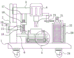
FIG. 1 is a schematic front view of the structure of the present invention;
FIG. 2 is a schematic top view of the structure of the placement board of the present invention;
fig. 3 is an enlarged view of the structure at a in fig. 1 according to the present invention.
In the figure: 1-device base, 2-support column, 3-cross arm, 4-driving motor, 5-boring cutter mounting shaft, 6-placing plate, 7-fixing frame, 8-bidirectional threaded screw rod, 9-bidirectional screw rod sleeve, 10-connecting rod, 11-clamping piece, 12-through hole, 13-limiting rod, 14-transmission rod, 15-unidirectional threaded screw rod, 16-unidirectional screw rod sleeve, 17-fixing rod, 18-rotating rod, 19-hand wheel, 20-water storage tank, 21-small water pump, 22-water pumping pipe, 23-spray head and 24-universal wheel.
Detailed Description
In order to make the objects, technical solutions and advantages of the present invention more apparent, the present invention is described in further detail below with reference to the accompanying drawings and embodiments. It should be understood that the specific embodiments described herein are merely illustrative of the utility model and are not intended to limit the utility model.
Referring to fig. 1-3, the present invention provides a technical solution: the utility model provides a portable removal bore hole equipment of electric drive, includes device base 1, and the vertical support column 2 that is provided with in rear side at device base 1's top, the top of support column 2 is provided with xarm 3 through slide bar slidable ground, can go up and down under adjustment mechanism's drive through xarm 3 slidable ground to can adjust according to the thickness of work piece inner wall, improve the practicality.
The other end of the cross arm 3 is provided with a driving motor 4, a boring cutter mounting shaft 5 is fixedly connected to an output shaft of the driving motor 4, a boring cutter can be mounted on the boring cutter mounting shaft 5, the boring cutter mounting shaft 5 can be driven to rotate by the aid of operation of the driving motor 4, so that the boring cutter is driven to rotate, and a workpiece can be bored by the aid of rotation of the boring cutter.
The front side of support column 2 transversely is provided with places board 6, be provided with fixture at the top of device base 1 and be located boring cutter installation axle 5 under, fixture includes fixed frame 7, fixed frame 7 transversely sets up in the surface of device base 1, the inside of fixed frame 7 rotationally transversely is provided with two-way screw lead screw 8, the equal threaded connection in both ends on 8 surfaces of two-way screw lead screw has two-way screw cover 9, the top of every two-way screw cover 9 all is provided with the connecting rod 10 that extends to place board 6 top, the inboard fixedly connected with supporting piece 11 of connecting rod 10, the front side of placing the surface of board 6 is provided with adjustment mechanism.
When needs are to the work piece centre gripping, at first rotate two-way screw lead screw 8, will drive two-way screw cover 9 through two-way screw when two-way screw lead screw 8 rotates and be close to each other, will drive the centre gripping piece 11 through connecting rod 10 when two-way screw cover 9 is close to each other and be close to each other, can will place the small-size work piece centre gripping on placing 6 surfaces of board when centre gripping piece 11 is close to each other to carry out the bore hole operation to it.
The height of the cross arm 3 can be adjusted by means of an adjusting mechanism, so that the device can be adapted to various small workpieces.
Further, the clamping pieces 11 are arranged in an inwards concave arc shape, rubber pads are arranged on the inner walls of the clamping pieces 11, and through holes 12 which are concentric with the boring cutter mounting shaft 5 are formed in the surface of the placing plate 6.
In this embodiment, because the clamping sheet 11 is arranged in the shape of an inward concave arc, the clamping sheet 11 can be more attached to the outer surface of a workpiece during clamping, and can be adapted to workpieces with different shapes, round workpieces can also be clamped, the stability after clamping can be increased by using a rubber pad, and the through hole 12 can enable the boring cutter mounting shaft 5 to pass through, so that the inner wall of the workpiece can be completely bored.
Furthermore, the bottom of the inner cavity of the fixed frame 7 is transversely provided with a limiting rod 13, the surface of the limiting rod 13 is slidably provided with a sliding block fixedly connected with the bidirectional screw rod sleeve 9, the other end of the bidirectional screw thread screw rod 8 is fixedly connected with a transmission rod 14 extending to the outside of the fixed frame 7, and the other end of the transmission rod 14 is fixedly connected with a knob.
In the embodiment, the knob is used for facilitating an operator to drive the bidirectional threaded screw rod 8 to rotate through the transmission rod 14, and the arranged limiting rod 13 can enable the sliding block to slide on the surface of the limiting rod, so that the bidirectional screw rod sleeve 9 plays a limiting role in moving.
Further, adjustment mechanism includes one-way screw lead screw 15, and one-way screw lead screw 15 is rotationally vertical to be provided with in the surface of placing board 6, and one-way screw lead screw 15's surface threaded connection has one-way lead screw cover 16, and the top of one-way lead screw cover 16 is provided with the dead lever 17 with 3 bottom fixed connection of xarm.
In the embodiment, the arranged one-way threaded screw rod 15 drives the one-way screw rod sleeve 16 to ascend and descend through threads when rotating, the cross arm 3 is driven to ascend and descend through the fixed rod 17 when the one-way screw rod sleeve 16 ascends and descends, and the driving motor 4 can be driven to ascend and descend through the ascending and descending of the cross arm 3, so that the adjustment can be performed according to the height difference of workpieces.
Furthermore, the bottom fixedly connected with first bevel gear on one-way screw lead screw 15 surface, the inside of support column 2 rotationally transversely runs through and is provided with dwang 18, and the one end of dwang 18 is provided with hand wheel 19, and the other end fixedly connected with of dwang 18 has the second bevel gear who is connected with the meshing of first bevel gear.
In this embodiment, the hand wheel 19 that sets up will drive the dwang 18 and rotate when rotating, will drive one-way screw lead screw 15 through first bevel gear and second bevel gear and rotate when dwang 18 rotates, makes things convenient for operating personnel to utilize the position of hand wheel 19 manual control needs bore hole.
Further, the vertical storage water tank 20 that is provided with in front of device base 1 surface, the top of storage water tank 20 is provided with small-size water pump 21, and small-size water pump 21's input is provided with the drinking-water pipe 22 that extends to storage water tank 20 inside, and one side of driving motor 4 is provided with shower nozzle 23, and shower nozzle 23 communicates with small-size water pump 21's output each other through the ripple hose, and the bottom of device base 1 is provided with universal wheel 24.
In this embodiment, the small water pump 21 that sets up can extract the inside rivers of storage water tank 20 through drinking-water pipe 22 at the during operation, makes rivers pass through shower nozzle 23 blowout to utilize spun rivers can be to the boring cutter cooling of adding man-hour, avoid the boring cutter to appear the problem of damage because of high temperature, utilize universal wheel 24 to make the device be convenient for remove, make the device can remove to the work piece storage department that needs the bore hole.
The working principle and the using process of the utility model are as follows: when a large number of small workpieces need to be bored, the device is firstly moved to a storage position of the small workpieces by using the universal wheel 24, then the small workpieces are placed on the surface of the placing plate 6, the knob is rotated, when the knob is rotated, the two-way threaded screw rod 8 is driven to rotate through the transmission rod 14, when the two-way threaded screw rod 8 is rotated, the two-way threaded screw rod sleeve 9 is driven to mutually approach through the two-way threads, when the two-way threaded screw rod sleeve 9 approaches mutually, the clamping pieces 11 are driven to mutually approach through the connecting rod 10, when the clamping pieces 11 approach mutually, the small workpieces placed on the surface of the placing plate 6 can be clamped, then the driving motor 4 is started, when the driving motor 4 works, the boring cutter mounting shaft 5 is driven to rotate, when the boring cutter mounting shaft 5 rotates, the mounted boring cutter can be driven to rotate, finally, the hand wheel 19 is manually rotated by an operator, when the hand wheel 19 rotates, the rotating rod 18 is driven to rotate, when the rotating rod 18 rotates, the one-way threaded screw rod 15 is driven to rotate through the first bevel gear and the second bevel gear, when the one-way threaded screw rod 15 rotates, the one-way screw rod sleeve 16 is driven to lift through threads, when the one-way screw rod sleeve 16 lifts, the cross arm 3 is driven to lift through the fixed rod 17, the driving motor 4 can be driven to lift through the lifting of the cross arm 3, and therefore the rotating boring cutter bores holes in clamped workpieces.
The present invention is not limited to the above preferred embodiments, and any modifications, equivalent substitutions and improvements made within the spirit and principle of the present invention should be included in the protection scope of the present invention.
Claims (6)
1. The utility model provides a portable removal bore hole equipment of electric drive which characterized in that: the device comprises a device base (1), wherein a supporting column (2) is vertically arranged on the rear side of the top of the device base (1), a cross arm (3) is arranged on the top of the supporting column (2) in a sliding mode through a sliding rod, a driving motor (4) is arranged at the other end of the cross arm (3), a boring cutter mounting shaft (5) is fixedly connected onto an output shaft of the driving motor (4), a placing plate (6) is transversely arranged on the front side of the supporting column (2), a clamping mechanism is arranged on the top of the device base (1) and is positioned under the boring cutter mounting shaft (5), the clamping mechanism comprises a fixing frame (7), the fixing frame (7) is transversely arranged on the surface of the device base (1), a bidirectional threaded screw rod (8) is rotatably and transversely arranged in the fixing frame (7), and two ends of the surface of the bidirectional threaded screw rod (8) are both in threaded connection with a bidirectional screw rod sleeve (9), the top of each two-way screw rod sleeve (9) is provided with a connecting rod (10) extending to the position above the placing plate (6), the inner side of each connecting rod (10) is fixedly connected with a clamping piece (11), and the front side of the surface of the placing plate (6) is provided with an adjusting mechanism.
2. An electrically driven portable mobile boring apparatus as claimed in claim 1, wherein: the clamping pieces (11) are arranged in an inwards concave arc shape, rubber pads are arranged on the inner walls of the clamping pieces (11), and through holes (12) which are concentric with the boring cutter mounting shaft (5) are formed in the surface of the placing plate (6).
3. An electrically driven portable mobile boring apparatus as claimed in claim 1, wherein: the bottom of fixed frame (7) inner chamber transversely is provided with gag lever post (13), the surface slidable ground of gag lever post (13) be provided with two-way lead screw cover (9) fixed connection's slider, the other end fixedly connected with of two-way screw lead screw (8) extends to fixed frame (7) outside transfer line (14), the other end fixedly connected with knob of transfer line (14).
4. An electrically driven portable mobile boring apparatus as claimed in claim 1, wherein: the adjusting mechanism comprises a one-way threaded screw rod (15), the one-way threaded screw rod (15) is rotatably and vertically arranged on the surface of the placing plate (6), the surface of the one-way threaded screw rod (15) is in threaded connection with a one-way screw rod sleeve (16), and a fixing rod (17) fixedly connected with the bottom of the cross arm (3) is arranged at the top of the one-way screw rod sleeve (16).
5. An electrically driven portable mobile boring apparatus as claimed in claim 4, wherein: the bottom fixedly connected with first bevel gear on one-way screw lead screw (15) surface, the inside of support column (2) rotationally transversely runs through and is provided with dwang (18), the one end of dwang (18) is provided with hand wheel (19), the other end fixedly connected with of dwang (18) with the second bevel gear that first bevel gear meshing is connected.
6. An electrically driven portable mobile boring apparatus as claimed in claim 1, wherein: the device is characterized in that a water storage tank (20) is vertically arranged on the front side of the surface of the device base (1), a small water pump (21) is arranged at the top of the water storage tank (20), an input end of the small water pump (21) is provided with a water pumping pipe (22) extending to the inside of the water storage tank (20), a spray head (23) is arranged on one side of the surface of the driving motor (4), the spray head (23) is communicated with an output end of the small water pump (21) through a corrugated hose, and universal wheels (24) are arranged at the bottom of the device base (1).
Priority Applications (1)
| Application Number | Priority Date | Filing Date | Title |
|---|---|---|---|
| CN202122442501.3U CN215698235U (en) | 2021-10-11 | 2021-10-11 | Portable removal bore hole equipment of electric drive |
Applications Claiming Priority (1)
| Application Number | Priority Date | Filing Date | Title |
|---|---|---|---|
| CN202122442501.3U CN215698235U (en) | 2021-10-11 | 2021-10-11 | Portable removal bore hole equipment of electric drive |
Publications (1)
| Publication Number | Publication Date |
|---|---|
| CN215698235U true CN215698235U (en) | 2022-02-01 |
Family
ID=80027758
Family Applications (1)
| Application Number | Title | Priority Date | Filing Date |
|---|---|---|---|
| CN202122442501.3U Active CN215698235U (en) | 2021-10-11 | 2021-10-11 | Portable removal bore hole equipment of electric drive |
Country Status (1)
| Country | Link |
|---|---|
| CN (1) | CN215698235U (en) |
-
2021
- 2021-10-11 CN CN202122442501.3U patent/CN215698235U/en active Active
Similar Documents
| Publication | Publication Date | Title |
|---|---|---|
| CN112518339A (en) | Machine parts polishes and drilling integration equipment | |
| CN112025320B (en) | Multi-station metal processing combined machine tool for processing inflating valve | |
| CN112355349A (en) | Machining device for multi-station forklift wheels | |
| CN215698235U (en) | Portable removal bore hole equipment of electric drive | |
| CN219632637U (en) | Perforating device that hardware fastener processing was used | |
| CN219310124U (en) | Radial drilling machine with drilling depth limiting mechanism | |
| CN215509108U (en) | Drilling bench drill | |
| CN212526115U (en) | Numerical control radial drilling machine | |
| CN212598995U (en) | Radial drilling machine | |
| CN212471414U (en) | Lifting device for engineering machinery maintenance | |
| CN209792364U (en) | pressure former in bicycle | |
| CN218460774U (en) | Semi-automatic positioning and adjusting mechanism for riveting tool | |
| CN219151655U (en) | Pin shaft outer circular hole positioning tool | |
| CN216577125U (en) | Inside grinding equipment of dovetail | |
| CN111014751A (en) | Precision adjusting device is used in radial drill processing | |
| CN215431601U (en) | Multi-angle workpiece drilling mechanism | |
| CN218532910U (en) | Processing equipment for cylinder hole of crankcase of compressor | |
| CN211162897U (en) | Adjustable workbench for drilling device of support piece | |
| CN216997496U (en) | Auxiliary installation lifting equipment for electric power engineering | |
| CN220372261U (en) | Angle steel tower hole making device | |
| CN217047152U (en) | High-precision multi-station positioning type flow guide shell combined die | |
| CN219004644U (en) | Radial drilling machine's regulation structure | |
| CN212822848U (en) | Universal radial drilling machine for drilling steel plate | |
| CN218591868U (en) | Efficient swing arm drilling machine of multistation | |
| CN220881762U (en) | Stable polishing and processing feeding device |
Legal Events
| Date | Code | Title | Description |
|---|---|---|---|
| GR01 | Patent grant | ||
| GR01 | Patent grant |