CN215685524U - Multifunctional wheel folding table - Google Patents
Multifunctional wheel folding table Download PDFInfo
- Publication number
- CN215685524U CN215685524U CN202120616397.2U CN202120616397U CN215685524U CN 215685524 U CN215685524 U CN 215685524U CN 202120616397 U CN202120616397 U CN 202120616397U CN 215685524 U CN215685524 U CN 215685524U
- Authority
- CN
- China
- Prior art keywords
- pull rod
- table top
- bearing frame
- top plate
- folding table
- Prior art date
- Legal status (The legal status is an assumption and is not a legal conclusion. Google has not performed a legal analysis and makes no representation as to the accuracy of the status listed.)
- Active
Links
Images


Classifications
-
- A—HUMAN NECESSITIES
- A47—FURNITURE; DOMESTIC ARTICLES OR APPLIANCES; COFFEE MILLS; SPICE MILLS; SUCTION CLEANERS IN GENERAL
- A47B—TABLES; DESKS; OFFICE FURNITURE; CABINETS; DRAWERS; GENERAL DETAILS OF FURNITURE
- A47B3/00—Folding or stowable tables
- A47B3/08—Folding or stowable tables with legs pivoted to top or underframe
- A47B3/083—Folding or stowable tables with legs pivoted to top or underframe with foldable top leaves
- A47B3/087—Folding or stowable tables with legs pivoted to top or underframe with foldable top leaves with struts supporting the legs
-
- A—HUMAN NECESSITIES
- A47—FURNITURE; DOMESTIC ARTICLES OR APPLIANCES; COFFEE MILLS; SPICE MILLS; SUCTION CLEANERS IN GENERAL
- A47F—SPECIAL FURNITURE, FITTINGS, OR ACCESSORIES FOR SHOPS, STOREHOUSES, BARS, RESTAURANTS OR THE LIKE; PAYING COUNTERS
- A47F5/00—Show stands, hangers, or shelves characterised by their constructional features
- A47F5/10—Adjustable or foldable or dismountable display stands
-
- B—PERFORMING OPERATIONS; TRANSPORTING
- B62—LAND VEHICLES FOR TRAVELLING OTHERWISE THAN ON RAILS
- B62B—HAND-PROPELLED VEHICLES, e.g. HAND CARTS OR PERAMBULATORS; SLEDGES
- B62B3/00—Hand carts having more than one axis carrying transport wheels; Steering devices therefor; Equipment therefor
- B62B3/02—Hand carts having more than one axis carrying transport wheels; Steering devices therefor; Equipment therefor involving parts being adjustable, collapsible, attachable, detachable or convertible
Abstract
The utility model relates to a multifunctional wheel folding table, which comprises a foldable table board, wherein the bottom of the table board is provided with a pair of foldable pulleys, one side of the bottom of the table board in the length direction is provided with a pull rod, and the pull rod can extend out from one side of the table board in the length direction in a pulling mode; at the same time, at least one bearing frame is also arranged at the bottom of the table panel, and can also extend out of the table panel in a drawing mode, and the bearing frame is rotationally locked in a state of being capable of erecting objects through a rotating mechanism. The folding table has the advantages that on the basis of the existing folding table, the pulleys, the pull rod, the bearing frame and the locking mechanism are additionally arranged, so that the double functions of the table and the trolley are realized, the folding table is ingenious in design, reasonable in structure and convenient to use, other objects can be pulled out by the table together, the table and the objects can be moved easily and labor-saving, and great convenience is brought to activities such as outdoor activities, exhibition and display of people.
Description
Technical Field
The utility model relates to a folding table, in particular to a multifunctional wheel folding table with a cart function after being folded.
Background
The common table has single function and is inconvenient to move, and particularly, the large-size table top spliced by the double table tops is adopted. Therefore, in order to enable the table to be convenient to carry and transport during traveling, exhibiting and selling and outdoor activities, the problem that the folding table is inconvenient to move is solved by arranging the pulleys in the folding table and sliding the pulleys. The problem is preferably solved by the earlier application of "a pulley and a folding table using the same" (publication number: CN 207492336U).
However, with the continuous improvement of the quality of life of people, the functional requirements on work and living goods are stronger and stronger, the desk is required to be portable, and the transportation and bearing function of the cart can also be better realized, so that when people go to outdoor activities or exhibition and display activities, display equipment, propaganda materials and the like for chairs, foods, exhibition and display can be pulled away together by utilizing the desk.
In view of the above situation, for example, the publication numbers CN203920813U (named as a multipurpose trolley capable of interchanging functions of a desk and a trolley) and CN210471373U (named as a multifunctional desk) disclose a desk structure capable of serving as a desk and a trolley, so as to achieve multiple purposes. However, the table tops of the two table structures are both of an integral structure, so that the table tops cannot be too large, otherwise the tables are inconvenient to carry and store; and objects to be transported are directly placed on the table top plate, and if the strength and the bearing of the table top plate are insufficient, the table top plate is easy to damage.
Further improvements to such tables are therefore desired.
Disclosure of Invention
The utility model aims to solve the technical problem that a multifunctional wheel folding table which is ingenious in design, reasonable in structure and convenient to use is provided aiming at the current situation of the prior art, the requirement of the market on a large-size table top is met, the function of a cart is realized, and the table can be pulled out together with other objects.
The technical scheme adopted by the technical problem to be solved by the utility model is as follows: a multifunctional wheel folding table comprises a folding table top plate formed by splicing two panels, wherein a pair of folding foot rest units is arranged at the bottom of the table top plate, and the multifunctional wheel folding table is characterized by also comprising:
the two pulleys are arranged at the bottom of the table top board in a foldable mode at intervals, and the wheels of the pulleys are folded at the bottom of the table top board in an unfolded state at the table; when the table is folded, the wheels of the pulleys extend out of the table top plate and can be contacted with the ground;
the pull rod is arranged at the bottom of the desktop plate and arranged in a T shape with the two pulleys, and the pull rod can extend out of the desktop plate in a drawing mode;
the bearing frame is provided with at least one bearing frame, is arranged at the bottom of the table top board, can extend out of the table top board in a drawing mode, and is rotationally locked in a state of being capable of erecting objects through a rotating mechanism.
Furthermore, a locking mechanism which can be locked together after being folded is arranged between the two panels so as to ensure that the two panels can be firmly locked together after being folded in half and cannot be separated due to the increase of bearing when the trolley is used.
Furthermore, the two pulleys can be installed along the length direction or the width direction of the table top board, but the installation in the width direction is preferred, namely the two pulleys are installed at two sides of the width direction of the bottom of the table top board and are adjacent to the splicing position of the two panels; correspondingly, the pull rod is arranged in the middle of one side of the length direction of the bottom of the table top plate, and the pull rod can extend out of one side of the table top plate along the length direction in a pulling mode. The arrangement skillfully utilizes the area in the foot rest unit and simultaneously does not interfere with the foot rest unit. When the trolley is used as a trolley, the height of the trolley is the length of one panel, and the trolley is very suitable for being dragged or pulled. However, if two pulleys are installed in the longitudinal direction, that is, installed on both sides of the lower side in the longitudinal direction of one panel, and the pull rod is installed in the middle of the upper side, the cart function can be achieved in the same manner, but the arrangement in the width direction is not reasonable in the structural layout.
Furthermore, the pull rod and the bearing frame can be arranged on different panels, wherein the bearing frame is preferably two, and comprises a first bearing frame and a second bearing frame which are arranged on two opposite sides of the same panel in the length direction, and under the folding state of the table, the first bearing frame and the pull rod are positioned on the same side and locked in the upward state relative to the table panel through the rotating mechanism, and the second bearing frame extends out of the butt joint of the two panels and is also locked in the upward state relative to the table panel through the rotating mechanism. When the multifunctional wheel folding table is used as a trolley, the first bearing frame positioned on the upper part can be used for hanging articles such as chairs or bags and the like which need to be pulled away together, and the second bearing frame positioned on the lower part can be used for placing articles such as refrigerating boxes or packing boxes containing food and the like, so that the articles can be easily pulled away together by using the multifunctional wheel folding table. In order to enable the pull rod and the bearing frame to be pulled out from the bottom of the table panel, the edge convex edge extending downwards of the table panel is provided with a abdicating notch for the first bearing frame and the pull rod to extend out.
Furthermore, the pulley comprises the wheel, a movable connecting arm and a fixed seat, one end of the movable connecting arm is pivoted on the fixed seat, and the other end of the movable connecting arm is connected with the wheel; the fixing seat is fixed at the bottom of the table top plate and is provided with two parallel and spaced side pieces, the length direction of the side pieces is consistent with the width direction of the table top plate, two ends of each side piece are respectively provided with an inner limiting groove and an outer limiting groove which can be used for stopping a limiting convex column connected to the movable connecting arm, and the edge of each side piece between the inner limiting groove and the outer limiting groove is processed into an arc shape. When the limiting column falls into the inner limiting groove, the wheels are positioned at the bottom of the table top plate; when the limiting column is in the outer limiting groove, the wheels extend out of the table top plate, and when the table is folded, the wheels can be in contact with the ground, and the table can be used as a cart.
Furthermore, the locking mechanism is arranged at the position adjacent to the abdicating notch and comprises a lock catch and a lock column which are respectively arranged on the two panels and can be locked with each other, wherein the lock catch is rotatably connected on a lock catch seat fixed with the panels. The locking mechanism is hidden between the two panels and is not exposed, so that the attractiveness of the desk is not influenced, and the manual operation is facilitated.
Further, the pull rod can be realized by adopting different structures, such as a relatively simple telescopic rod type structure; but preferably, the draw-bar structure of a conventional draw-bar box can be adopted, the draw-bar structure comprises a pair of draw-bar outer tubes fixed at the bottom of the table top plate, a draw-bar telescopic rod is assembled in each draw-bar outer tube, a handle is arranged at the upper end of each draw-bar telescopic rod, a button is arranged on each handle, and the button controls the draw-bar telescopic rod to stretch and position.
Furthermore, the bearing frame can be made into a U-shaped structure and comprises a pair of outer tubes of the bearing frame fixed at the bottom of the table top plate, and telescopic rods of the bearing frame which can be telescopically positioned are assembled in the outer tubes of the bearing frame, so that articles can be placed conveniently and the bearing strength is better; the telescopic rod of the bearing frame is U-shaped, and the rod body of the bearing frame is provided with the rotating mechanism. The loading ledges may of course also be designed in other ways, without being restricted thereto.
Further, the telescopic rod of the bearing frame can be formed by connecting an upper rod and two lower rods which are separated, the upper rod is U-shaped, two ends of the upper rod are respectively connected with the lower rods through the rotating mechanism, the end parts of the lower rods are flat after two sides are flattened, the outer edge surfaces of the lower rods are sequentially provided with a vertical plane, an inclined plane and an arc-shaped surface along the length direction of the lower rods, correspondingly, the middle of the end parts of the upper rod is provided with a containing opening, the end parts of the lower rods are inserted into the containing opening and connected through a rotating shaft, and the rotating mechanism capable of rotationally locking the bearing frame is formed by the rotating shaft and end structures of the upper rod and the lower rods. Thus, when the upper rod is pulled out, the wall surface of the accommodating opening of the upper rod opposite to the end part of the lower rod is rotated to be abutted against the vertical plane of the end part of the lower rod, and the inclined surface on the upper rod can limit the relative rotation of the upper rod and the lower rod, so that the upper rod can be locked in a 90-degree or approximately 90-degree upward state. Only when external force acts, the upper rod can rotate along the inclined plane and the arc-shaped surface until the upper rod and the lower rod are in a horizontal state, and at the moment, the upper rod can be retracted into the outer pipe of the bearing frame.
Furthermore, the bottom of the table top board adjacent to the joint of the two panels is provided with a transverse supporting rod in the width direction, and the fixed seat and the transverse supporting rod are connected into a whole so as to fully utilize the original structure of the folding table.
Further, the table top plate is a hollow blow-molded plate, so that the table top plate is better suitable for outdoor use.
Compared with the prior art, the utility model has the advantages that: the folding table has the advantages that on the basis of the existing folding table, the pulleys, the pull rod, the bearing frame and the locking mechanism are additionally arranged, so that the double functions of the table and the trolley are realized, the folding table is ingenious in design, reasonable in structure and convenient to use, other objects can be pulled out by the table together, the table and the objects can be moved easily and labor-saving, and great convenience is brought to activities such as outdoor activities, exhibition and display of people.
Drawings
Fig. 1 is a perspective view of a foldable table with multi-functional wheels according to an embodiment of the present invention in an unfolded state.
Fig. 2 is a schematic view of fig. 1 in an inverted state.
Fig. 3 is a schematic view of fig. 2 in a state that the pull rod, the first bearing frame and the pulley are pulled out.
Fig. 4 is a perspective view (with the pull rod pulled out) of the foldable table with the multi-functional wheels according to the embodiment of the present invention in a folded state.
Fig. 5 is a schematic view of fig. 4 after the loading ledges have been pulled out.
Fig. 6 is a perspective view of the telescoping bar of the loading frame according to the embodiment of the present invention.
FIG. 7 is a view reflecting the locked state of the telescoping rod of the loading frame of FIG. 6.
Fig. 8 is an enlarged schematic view of fig. 7 at a.
Fig. 9 is an exploded view of fig. 7.
Fig. 10 is an enlarged schematic view of fig. 9 at B.
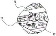
Fig. 11 is a schematic view showing the structure of the locking mechanism in the unlocked state.
Fig. 12 is an enlarged view of fig. 11 at C.
Fig. 13 is a schematic view showing the locking mechanism in the locked state.
Fig. 14 is an enlarged view of fig. 13 at D.
Detailed Description
The utility model is described in further detail below with reference to the accompanying examples.
Referring to fig. 1 to 3, the multifunctional wheel folding table comprises a table top board 1, a supporting frame 4 fixed at the bottom of the table top board and composed of a horizontal supporting rod and a longitudinal supporting rod, a pair of foot rest units 2 connected to the supporting frame and capable of being movably folded, two pulleys 3, a bearing frame 6 and a pull rod 5, wherein: the table top board 1 is a double-spliced panel formed by splicing a left panel 1a and a right panel 1b and can be folded, the left panel 1a and the right panel 1b adopt hollow blow-molded panels, the two panels have the same size, and the shapes are basically the same except that some grooves at the bottom are designed to be slightly different. The table top 1, the frame 4 and the foot stool unit 2 of the present invention may be modified or adopt other known techniques in addition to the embodiments shown in the figures.
The multifunctional wheel folding table has the functions of a conventional table and a trolley, and is mainly realized by pulleys 3, a pull rod 5 and a bearing frame 6 which are arranged at the bottom of a table top plate. Wherein:
two pulleys 3 are arranged at two sides of the bottom of the right panel 1b in the width direction and are adjacent to the splicing part 12 of the left panel and the right panel, and when the desk is unfolded, the wheels 31 of the pulleys can fold the bottom of the desk panel 1; when the table is folded, the wheels 31 of the pulley can extend out of the table top 1 and slide in contact with the ground. The pulley 3 is mainly composed of a wheel 31, an active connecting arm 32 and a fixed seat 33, the fixed seat 33 is welded with a transverse supporting rod 41 in the frame into a whole, the pulley is provided with two parallel and spaced side pieces 35, the length direction of the side pieces is consistent with the width direction of the table top plate, inner and outer limiting grooves 36 and 37 are arranged at two ends of the side pieces and can be used for clamping a limiting convex column 34 connected to the active connecting arm 32, and the edge of the side piece between the inner and outer limiting grooves 36 and 37 is processed into an arc shape. One end of the movable connecting arm 32 is pivoted on the fixed seat 33, and the other end is connected with the wheel axle of the wheel 31. When the movable connecting arm 32 turns to the inner side, the limiting convex column 34 thereon can be clamped in the inner limiting groove 36 of the fixing seat to be locked, so that the wheel 31 is in a folding state, and if unlocking is required, the movable connecting arm 32 is only needed to be manually operated, so that the limiting convex column 34 is separated from the inner limiting groove 36. Similarly, when the movable connecting arm 32 is turned to the outside, the limiting convex column 34 thereon can be blocked in the external limiting groove 37 of the fixing base to be locked, so that the wheel 31 is in the extending state. Thus, the wheels 31 are locked in the open state after outward rotation or the folding state after inward rotation through the fixed seat 33 and the movable connecting arm 32, the structure is simple, the use is convenient, the design is reasonable, and the folding of the table top plate and the folding of the foot stand unit cannot be influenced.
Referring to fig. 2 and 3, the pull rod 5 is installed at one side of the length direction of the bottom of the table top plate, in the embodiment, the pull rod 5 is installed in the middle of the right side of the right panel 1b and arranged in a T shape with the two pulleys 3, and the pull rod 5 can extend out from the bottom of the right panel 1b along the length direction in a pulling manner, so that the edge convex edge extending downwards from the middle part of the right side of the right panel is provided with a abdicating notch 11 for pulling out the pull rod. The pull rod 5 can be realized in different structures, such as a relatively simple telescopic rod-like structure. However, the draw bar 5 shown in the drawing of this embodiment is a draw bar structure of a conventional draw bar box, and mainly includes a pair of draw bar outer tubes 51 fixed at the bottom of the table top, a draw bar telescopic rod 54 is assembled in the draw bar outer tubes, a handle 53 is arranged at the upper end of the draw bar telescopic rod 54, a button 52 is arranged on the handle, and the draw bar telescopic rod 54 is controlled by the button 52 to extend and retract to be positioned. The pull rod is pulled out when the table is used and retracted to the bottom of the table top when the table is not used.
The loading frame 6 can be one or more than one, but generally is preferably two in the embodiment in order to meet the hanging and placing requirements, so that the area in the foot stand unit is skillfully utilized, and meanwhile, the foot stand unit is not interfered. The supporting frame 6 is also extended out of the table top 1 by pulling (similarly, the edge protruding edge extending downward corresponding to the panel is provided with an abdicating notch 11 for pulling the supporting frame out), and is locked in an upward state relative to the table top by a rotating mechanism 620.
The first bearing frame 6a and the second bearing frame 6b of the present embodiment are disposed on a panel different from the pull rod, that is, the left panel 1a, and are mounted on two opposite sides of the left panel in the length direction, so that in the folded state of the table, the first bearing frame 6a and the pull rod 5 are on the same side, and the second bearing frame 6b extends from the butt joint 12 of the left and right panels (i.e., the gap portion between the splicing portions of the left and right panels) and is on the same side as the lower pulley 3, so that the first bearing frame 6a is suitable for hanging articles such as chairs, and the second bearing frame 6b is suitable for placing articles such as packing boxes, and cold storage boxes containing food, etc., as shown in fig. 5.
To facilitate the hanging/placing of objects and to provide a good load-bearing strength, the carrying frame 6 may be formed as a U-shaped structure comprising a pair of outer carrying frame tubes 61 fixed to the bottom of the table top, inside which telescopic U-shaped carrying frame telescopic rods 62 are telescopically arranged. The shaft of the telescoping member 62 is provided with a pivoting mechanism 620 by which the telescoping member can be locked in a generally upwardly facing position relative to the table top, although the telescoping member can be designed in other ways and is not limited thereto.
As shown in fig. 6-10, the telescopic rod 62 of the loading frame is formed by connecting a split upper rod 621 and two lower rods 622, the upper rod 621 is U-shaped, two ends of the upper rod 621 are respectively connected with the lower rods 622 through a rotating mechanism 620, wherein the end of the lower rod 622 is flat with two sides flattened, and the outer edge surface 624 sequentially has a vertical plane, a slope and an arc surface along the length direction of the lower rod. The upper rod 621 has an accommodating hole 625 at the middle of its end, the lower rod end is inserted into the accommodating hole 625 and connected to the upper rod 521 via a rotating shaft 623, and the rotating shaft 623 and the end structures of the upper and lower rods constitute a rotating mechanism capable of locking the carriage in rotation. Thus, when the upper rod 621 is pulled out, the wall surface of the receiving opening of the upper rod opposite to the end of the lower rod is rotated to abut against the vertical plane of the end of the lower rod, and the inclined surface of the upper rod is beneficial to limit the relative rotation of the upper rod and the lower rod, so that the upper rod 621 can be locked in a 90-degree or approximately 90-degree upward state. Only when an external force is applied, the upper rod 621 can rotate along the inclined surface and the arc surface until the upper rod and the lower rod are in a horizontal state, and at the moment, the upper rod 621 can be retracted into the outer tube 61 of the bearing frame. The position limitation between the outer tube 61 and the telescopic rod 62 of the bearing frame can be realized by a conventional telescopic rod positioning mode, for example, by a conventional position limiting hole arranged on the outer tube and a conventional position limiting pin arranged on the telescopic rod, and the position limitation is not specifically expanded.
When the multifunctional wheel folding table is unfolded, the wheels on the pulleys are folded at the bottom of the table top plate, and when the table is used, as shown in figure 1; when the multifunctional wheel folding table is folded, the wheels on the pulleys extend out of the table surface, and the pull rod is pulled out at the same time, so that the table can be pushed or pulled, as shown in fig. 4. If some articles are to be moved at the same time, the two loading frames are pulled out, and the articles are hung or placed on the loading frames, as shown in fig. 5. Therefore, the multifunctional wheel folding table has multiple purposes, and the table and the objects can be moved easily and laborsavingly.
In addition, the two panels of the traditional table are fastened and fixed by two plastic chucks after being folded in half, and the multifunctional wheel folding table can be used as a trolley, so that objects, such as four chairs, can be placed on the bearing frame to form a set of one table and four chairs, and one person can finish dragging. Thus, the plastic clip alone is not sufficient to hold the two panels together, and the weight of four chairs is not possible. To this end, the multifunctional wheel folding table is additionally provided with a mechanical structure between the two panels, and the mechanical structure can adopt a locking mechanism (the left panel 1a is not shown) as shown in figures 11-14. The locking mechanism is arranged at the position adjacent to the abdicating notch 11 and mainly comprises a lock catch 72 and a lock column 71, and a clamping groove is arranged on the lock catch 72 and can be used for clamping the lock column 71; the lock catch 72 is hinged on the lock catch seat 73 and can rotate, and the lock catch seat 73 is fixed on the right panel 1b through a screw; the lock cylinder 71 is provided on the left panel 1a and can be directly riveted to the crosspiece of the first carrier 6 a. When in operation, the lock catch 72 is pulled by hand to complete locking or unlocking, the operation is convenient, so the locking mechanism can firmly lock the two panels, the trouble that the two panels are easy to be separated after bearing objects is solved, and the locking mechanism is not exposed at the edge of the table and can not influence the aesthetic property of the table. However, the above is only one preferred embodiment of the locking mechanism, and the locking mechanism can be modified in structure without being limited thereto.
Although preferred embodiments of the present invention have been described in detail hereinabove, it should be clearly understood that modifications and variations of the present invention are possible to those skilled in the art. Any modification, equivalent replacement, or improvement made within the spirit and principle of the present invention should be included in the protection scope of the present invention.
Claims (10)
1. The utility model provides a multi-functional wheel folding table, includes the folding desktop board that constitutes by two panel concatenations, and a pair of folding foot rest unit, its characterized in that are equipped with to the bottom of desktop board: also comprises
The two pulleys are arranged at the bottom of the table top board in a foldable mode at intervals, and the wheels of the pulleys are folded at the bottom of the table top board in an unfolded state at the folding table; when the folding table is in a folding state, the wheels of the pulleys extend out of the table top plate and can be contacted with the ground;
the pull rod is arranged at the bottom of the desktop plate and arranged in a T shape with the two pulleys, and the pull rod can extend out of the desktop plate in a drawing mode;
the bearing frame is provided with at least one bearing frame, is arranged at the bottom of the table top board, can extend out of the table top board in a drawing mode, and is rotationally locked in a state of being capable of erecting objects through a rotating mechanism.
2. The multi-function wheel folding table as claimed in claim 1, wherein: and a locking mechanism which can be locked together after being folded is also arranged between the two panels.
3. The multi-function wheel folding table as claimed in claim 2, wherein: the two pulleys are arranged on two sides of the width direction of the bottom of the table top plate and are adjacent to the splicing position of the two panels; correspondingly, the pull rod is arranged in the middle of one side of the length direction of the bottom of the table top plate, and the pull rod can extend out of one side of the table top plate along the length direction in a pulling mode.
4. A multi-function wheel folding table as claimed in claim 3, wherein: the two bearing frames comprise a first bearing frame and a second bearing frame which are arranged on two opposite sides of the same panel in the length direction, and in the folding state of the folding table, the first bearing frame and the pull rod are positioned on the same side and locked in the upward state relative to the table top plate through the rotating mechanism; an abdicating notch for the first bearing frame and the pull rod to extend out is arranged on the edge convex edge which is extended downwards on the table top plate.
5. The multi-function wheel folding table as claimed in claim 1, wherein: the pulley comprises the wheel, a movable connecting arm and a fixed seat, one end of the movable connecting arm is pivoted on the fixed seat, and the other end of the movable connecting arm is connected with the wheel; the fixing seat is fixed at the bottom of the table top plate and is provided with two parallel and spaced side pieces, the length direction of the side pieces is consistent with the width direction of the table top plate, two ends of each side piece are respectively provided with an inner limiting groove and an outer limiting groove which can be used for stopping a limiting convex column connected to the movable connecting arm, and the edge of each side piece between the inner limiting groove and the outer limiting groove is processed into an arc shape.
6. The multi-function wheel folding table as claimed in claim 4, wherein: the locking mechanism is arranged at the position adjacent to the abdicating notch and comprises a lock catch and a lock column which are respectively arranged on the two panels and can be mutually locked, wherein the lock catch is rotationally connected on a lock catch seat fixed with the panels.
7. The multi-function wheel folding table as claimed in claim 1, wherein: the pull rod adopts a pull rod structure of a conventional pull rod box and comprises a pair of pull rod outer tubes fixed at the bottom of the table top plate, a pull rod telescopic rod is assembled in each pull rod outer tube, a handle is arranged at the upper end of each pull rod telescopic rod, a button is arranged on each handle, and the button controls the telescopic positioning of the pull rod telescopic rods.
8. The multi-function wheel folding table as claimed in any one of claims 1 to 7, wherein: the bearing frame is of a U-shaped structure and comprises a pair of outer tubes of the bearing frame fixed at the bottom of the table top plate, and telescopic rods of the bearing frame which can be telescopically positioned are assembled in the outer tubes of the bearing frame; the telescopic rod of the bearing frame is U-shaped, and the rod body of the bearing frame is provided with the rotating mechanism.
9. The multi-function wheel folding table as claimed in claim 8, wherein: bear the frame telescopic link adopt the upper boom and two lower arms of components of a whole that can function independently to be connected and constitute, the upper boom be the U-shaped, its both ends pass through respectively rotary mechanism connect a lower arm, wherein the tip of lower arm is the platykurtic after both sides are cut flat, and the outer fringe face has along the ascending vertical plane of lower arm length direction, inclined plane and arcwall face according to the preface, correspondingly, the tip centre of upper boom be equipped with the mouth that holds, the lower arm tip insert and hold in the mouth and connect through the pivot, constitute by the end structure of this pivot and upper and lower arm rotary locking's rotary mechanism can bear the frame.
10. The multi-function wheel folding table as claimed in claim 5, wherein: the bottom of the table top board near the joint of the two panels is provided with a transverse supporting rod in the width direction, and the fixed seat and the transverse supporting rod are connected into a whole.
Applications Claiming Priority (2)
| Application Number | Priority Date | Filing Date | Title |
|---|---|---|---|
| CN2020223604365 | 2020-10-21 | ||
| CN202022360436 | 2020-10-21 |
Publications (1)
| Publication Number | Publication Date |
|---|---|
| CN215685524U true CN215685524U (en) | 2022-02-01 |
Family
ID=79278296
Family Applications (3)
| Application Number | Title | Priority Date | Filing Date |
|---|---|---|---|
| CN202120616397.2U Active CN215685524U (en) | 2020-10-21 | 2021-03-25 | Multifunctional wheel folding table |
| CN202111185729.7A Pending CN113925275A (en) | 2020-10-21 | 2021-10-12 | Telescopic folding table |
| CN202122451548.6U Active CN216293323U (en) | 2020-10-21 | 2021-10-12 | Telescopic folding table |
Family Applications After (2)
| Application Number | Title | Priority Date | Filing Date |
|---|---|---|---|
| CN202111185729.7A Pending CN113925275A (en) | 2020-10-21 | 2021-10-12 | Telescopic folding table |
| CN202122451548.6U Active CN216293323U (en) | 2020-10-21 | 2021-10-12 | Telescopic folding table |
Country Status (1)
| Country | Link |
|---|---|
| CN (3) | CN215685524U (en) |
Families Citing this family (2)
| Publication number | Priority date | Publication date | Assignee | Title |
|---|---|---|---|---|
| CN114498218B (en) * | 2022-03-02 | 2024-04-09 | 沈阳旭阳中冶座椅有限公司 | High-speed railway table top with socket |
| CN114601305A (en) * | 2022-04-01 | 2022-06-10 | 上海小点汽车科技有限公司 | Portable clothing storage and display mechanism |
-
2021
- 2021-03-25 CN CN202120616397.2U patent/CN215685524U/en active Active
- 2021-10-12 CN CN202111185729.7A patent/CN113925275A/en active Pending
- 2021-10-12 CN CN202122451548.6U patent/CN216293323U/en active Active
Also Published As
| Publication number | Publication date |
|---|---|
| CN216293323U (en) | 2022-04-15 |
| CN113925275A (en) | 2022-01-14 |
Similar Documents
| Publication | Publication Date | Title |
|---|---|---|
| CN215685524U (en) | Multifunctional wheel folding table | |
| US7784816B2 (en) | Flat platform cart with collapsible casters | |
| CN201005243Y (en) | Folding table device | |
| US20170340100A1 (en) | Foldable Banquet Table and Bench Set | |
| WO2012092773A1 (en) | Vertically-elevating sliding foldable frame | |
| US11547205B2 (en) | Collapsible measuring and cutting craft table | |
| US7089610B2 (en) | Portable hammock | |
| CN113892754A (en) | Telescopic folding table | |
| CN201437418U (en) | Foldable basket | |
| CN216723618U (en) | Telescopic folding table | |
| CN216316228U (en) | Telescopic table plate of folding table | |
| CN108813920A (en) | Folding table and its folded frame with folded frame | |
| CN212815008U (en) | Foldable table | |
| CN216316232U (en) | Telescopic folding table frame | |
| CN219382532U (en) | Folding handcart and folding handcart side frame capable of being used as table | |
| CN207191117U (en) | A kind of instrument trolley | |
| CN209152517U (en) | Folding table and its folded frame with folded frame | |
| CN207889758U (en) | Portable folding carrier | |
| CN217365144U (en) | Folding support frame and folding bedstead | |
| CN219769933U (en) | Folding gathering type hand buggy | |
| CN212637513U (en) | Triple-linkage luggage barrow | |
| CN218229045U (en) | Handcart is folded to extendible formula | |
| CN215663513U (en) | Foldable extensible handcart | |
| CN201091339Y (en) | Portable type fold combination desk | |
| CN219183053U (en) | Movable carrier |
Legal Events
| Date | Code | Title | Description |
|---|---|---|---|
| GR01 | Patent grant | ||
| GR01 | Patent grant |