CN216316232U - Telescopic folding table frame - Google Patents
Telescopic folding table frame Download PDFInfo
- Publication number
- CN216316232U CN216316232U CN202122458589.8U CN202122458589U CN216316232U CN 216316232 U CN216316232 U CN 216316232U CN 202122458589 U CN202122458589 U CN 202122458589U CN 216316232 U CN216316232 U CN 216316232U
- Authority
- CN
- China
- Prior art keywords
- frame
- folding table
- sliding rail
- rod piece
- piece
- Prior art date
- Legal status (The legal status is an assumption and is not a legal conclusion. Google has not performed a legal analysis and makes no representation as to the accuracy of the status listed.)
- Active
Links
Images


Landscapes
- Tables And Desks Characterized By Structural Shape (AREA)
Abstract
A telescopic foldable desk frame is composed of a fixed frame able to be pivoted around the pivot axle of pivot joint unit, a pair of foldable foot rest units connected to said fixed frame, and a slide track between said slide track and fixed frame. The table frame is connected with the table plate through the sliding rail on the table frame, the sliding rail is linked with the table plate and can slide relative to the fixed frame on the upper part of the table frame, and the purpose of telescopic the table plate of the folding table is achieved, so that the limitation that the table plate can only be folded in half and cannot be stretched in the traditional folding table frame is broken through; meanwhile, the roller skating device is designed, and the folding table is quite convenient to move.
Description
Technical Field
The utility model relates to a table frame, in particular to a telescopic folding table frame.
Background
The telescopic table is a table capable of enlarging the area of a table top, is used more at home, and particularly needs to be unfolded and extended when the number of people having meals in the home is greatly changed, so that the telescopic table is suitable for being used by more people, and the occupied space can be reduced by shortening the telescopic table when the number of people is small.
The folding table is a table which can be folded to reduce the placing space, thus being convenient to carry. For example, in a common folding table, when the table is opened, the two butt joint panels can be butt jointed with each other to form a table board, when the table is folded, the two butt joint panels can be folded together, and the folded foot rest can be hidden in the two butt joint panels after being combined. Such a folding table structure is disclosed in publication No. CN207428721U, specifically: the foldable frame mainly comprises a left panel and a right panel which are the same in size and shape, a left frame and a right frame which are fixed at the bottoms of the left panel and the right panel respectively, and two foldable supports which are movably connected with the left frame and the right frame, wherein a connecting cross rod is arranged at the butt joint of the left panel and the right panel, the left frame and the right frame comprise connecting vertical rods which are parallel to each other and are fixed at the two side parts of the bottoms of the left panel and the right panel respectively, and a rotating shaft is rotatably arranged between the two connecting vertical rods. However, although the foldable table can be folded, the table top cannot be stretched, and after the foldable table is unfolded, the length of the table top is fixed and cannot be extended, so that the foldable table cannot be adjusted according to the number of articles to be placed or the number of people to sit on.
Along with the continuous improvement of the life quality of people, the functional requirements on work and living goods are stronger and stronger, and a single telescopic table or a folding table cannot well meet the daily life needs of people.
Disclosure of Invention
The first technical problem to be solved by the present invention is to provide a foldable table frame with a retractable table top, so as to achieve the integrated functions of folding and extension.
The second technical problem to be solved by the present invention is to provide a retractable folding table frame for a folding table, which can slide via wheels.
The first technical problem to be solved by the utility model adopts the technical scheme that: the telescopic folding table frame comprises a fixed frame capable of being folded around a pin joint shaft of a pin joint device, a pair of foldable foot rest units connected with the fixed frame, and a sliding rail, wherein the fixed frame is provided with the pin joint device, a longitudinal supporting rod piece and a transverse supporting rod piece which are connected with the pin joint device.
Preferably, the slide rail is provided with a slide groove arranged along the length direction, and a stop pin piece connected with the longitudinal support rod piece is arranged in the slide groove. The pin blocking piece has the functions of connecting the sliding rail and the longitudinal support rod piece and blocking and limiting.
Preferably, the longitudinal support rod is a hollow pipe; the sliding rail is a strip-shaped plate, is arranged between the longitudinal support rod piece and the main panel of the folding table, and slides back and forth along with the main panel of the folding table relative to the longitudinal support rod piece. By adopting the structure, the arrangement of the frame and the foot rest unit is not influenced, and the foot rest unit can be hidden in the edge convex edge which is arranged in a downward extending way of the main panel, so that the integral appearance is not influenced.
Preferably, two or more than two sliding grooves are arranged on the sliding rail at intervals, and the length of each sliding groove is not less than half of the length of the movable panel. When the main panel is unfolded and slides to the maximum displacement, one end of the sliding chute, which is adjacent to the frame connecting shaft, is collided with the stop pin piece; when the main panel is restored, one end of the sliding groove, which is far away from the frame connecting shaft, is collided with the stop pin piece.
The second technical problem to be solved by the present invention is to adopt the following technical scheme: and two pulley pieces which are arranged at two ends of the transverse support rod piece in a spacing and foldable manner. Under the unfolded state of the folding table, the wheels of the pulley pieces are folded at the bottom of the table plate; when the folding table is in a folding state, the wheels of the pulley pieces extend out of the table plate and can be in contact with the ground so as to slide.
Preferably, the pulley member comprises a wheel, a movable connecting arm and a fixed seat, one end of the movable connecting arm is pivoted on the fixed seat, and the other end of the movable connecting arm is connected with the wheel; the fixing seat is integrally arranged on the transverse supporting rod piece and is provided with two parallel and spaced side pieces, the length direction of the side pieces is consistent with that of the transverse supporting rod piece, two ends of each side piece are respectively provided with an inner limiting groove and an outer limiting groove for stopping a limiting convex column connected to the movable connecting arm, and the edge of each side piece between the inner limiting groove and the outer limiting groove is processed into an arc shape. When the limiting column is placed in the inner limiting groove, the wheel is positioned at the bottom of the table plate; when the limiting column is arranged in the outer limiting groove, the wheels extend out of the table plate, and when the table is folded, the wheels can be in contact with the ground, so that the trolley can be used as a trolley.
Compared with the prior art, the utility model has the advantages that: the table frame is connected with the table plate through the sliding rail on the table frame, the sliding rail is linked with the table plate and can slide relative to the fixed frame on the upper part of the table frame, and the purpose of telescopic the table plate of the folding table is achieved, so that the limitation that the table plate can only be folded in half and cannot be stretched in the traditional folding table frame is broken through; meanwhile, the roller skating device is designed, and the folding table is quite convenient to move.
Drawings
Fig. 1 is a schematic view of the desk top of the present invention in an extended and lengthened state.
Fig. 2 is a schematic view of fig. 1 in an inverted state.
Figure 3 is an exploded view of the removable panel of figure 1 (utility pole not shown).
FIG. 4 is a schematic view of the table top of the present invention in a retracted, unarmed state.
Fig. 5 is an exploded view of the table.
Fig. 6 is an exploded schematic view of fig. 1 (lamp post not shown).
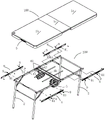
Fig. 7 is a schematic view of fig. 6 in an inverted state.
Fig. 8 is an external view of the embodiment of the present invention in a folded package state.
Fig. 9 is a perspective view of the embodiment of the present invention in a folded state (with the tie bar pulled out).
Fig. 10 is a schematic view of fig. 9 after the loading ledges have been pulled out.
Detailed Description
The utility model is described in further detail below with reference to the accompanying examples.
As shown in fig. 1 to 10, the present embodiment is a folding table equipped with a table frame according to the present invention, and includes a table frame 200 of the present invention, and a table board 100, a pull rod 5, a bearing frame 6, and the like, wherein:
the table board 100 comprises a left main panel 1a, a right main panel 1b and a movable panel 1c, wherein the left main panel 1a and the right main panel 1b have the same shape and size or are basically the same (as shown in fig. 5). But is not limited thereto, and both the main panels 1a and 1b can be adjusted according to specific needs. The movable panel 1c can be placed between the two main panels 1a and 1b to lengthen the length of the table, and the movable panel 1c can be one or more, but one of the embodiments is preferred. In order to better adapt to outdoor use, the two main panels 1a and 1b and the movable panel 1c are hollow blow-molded panels (the concave structure at the bottom of the panels is omitted in the figure). As in the conventional case, the opposite side portions of the two main panels 1a and 1b, that is, the lower portions of the butting surfaces to be butted against each other, are integrally formed with the recesses 14 and the protrusions 13 distributed in a staggered manner, in the state where the two main panels 1a and 1b are butted against each other, the upper side portions of the butting surfaces are in plane butting, and the lower side portions are in sequential tabling butting with the recesses 14 and the protrusions 13 therebetween, so that the table plate is in the conventional double-tiled panel state shown in fig. 3 and 4. Similarly, the left and right sides of the movable panel 1c are butt joint surfaces respectively butt-jointed with the two main panels, the lower parts of the two sides are also integrally formed with the grooves 14 and the projections 13 which are distributed in a staggered way, when the movable panel 1c is butt-jointed with the two main panels 1a and 1b, the upper side parts of the butt joint surfaces are also in plane butt joint, the lower side parts are also in sequential tabling butt joint by the grooves 14 and the projections 13 which are arranged between the upper side parts, namely, the projections 13 on the movable panel 1c are tabling with the grooves 14 on the main panels 1a and 1b, the grooves on the movable panel 1c are tabling with the projections 13 on the main panels 1a and 1b, and the table is in the extended and lengthened state shown in fig. 1 and 2. By adopting the structure, the structural strength of the butt joint of the panels is improved, the butt joint seam can be reduced, and the flatness and the attractiveness of the table board 100 can be ensured.
As shown in fig. 2 and 4, two clips 17 may be further installed at the bottom of the movable panel 1C, and the clips 17 may be C-shaped clips which can be clipped on the supporting legs 21 of the foot stand unit 2 when not in use, so as to be convenient for taking. In addition, a receptacle 15 is provided at the corner of one of the major panels for receiving an object, such as a light pole. In order to keep the desktop flat, the jack is provided with a plug cover, and when the telegraph pole is not installed, the plug cover can be used for plugging.
The table frame 200 is mainly composed of a fixed frame 4, a slide rail 8 which is in sliding fit with the fixed frame 4, and a left foot frame unit 2 and a right foot frame unit 2 which can be movably folded, wherein the fixed frame 4 is formed by connecting a front pin joint device 41, a rear pin joint device 41, a plurality of transverse and longitudinal support rod pieces 43 and 42 and the like (the transverse and front and rear directions are the width directions of the table plate, and the longitudinal and left and right directions are the length directions of the table plate), and the transverse support rod pieces 43 and the longitudinal support rod pieces 42 are both hollow pipe fittings and are preferably square pipes. Four longitudinal support rods 42 are provided, opposite to each other, and are connected to the pivoting devices 41, respectively, two transverse support rods 2 are provided, and are connected between the front and rear pivoting devices 41, respectively, and the left and right portions of the entire frame can be folded around the pivoting shafts 411 of the front and rear pivoting devices 41. The left and right foot rest units 2 are respectively and correspondingly connected with the longitudinal support rod 42 of the fixed frame, and because the two main panels 1a and 1b of the folding table slide and stretch relative to the fixed frame 4, the left and right foot rest units 2 are not connected with the two main panels 1a and 1 b. Left and right foot rest unit 2 structure is the same basically, including pivot 22, two supporting legs 21 and crosspiece 23, can hold movable panel and two wheels inside after doing benefit to this folding table, and wherein pivot 22 is the door shape with two supporting legs 21 and arranges, and pivot 22 welds the upper end at two supporting legs 21, and the rotatable setting in the shaft hole of two vertical support member 42 in the both ends of pivot 22 for foot rest unit 2 can rotate for table 100. The supporting legs 21 are vertical hollow tubes, and a supporting rod 24 is hinged between the longitudinal supporting rod 42 and the corresponding supporting leg 21, and the supporting rod 24 is mainly composed of a hinged upper connecting rod and a hinged lower connecting rod and can be folded. Adopt this foot rest unit structure neither to influence the flexible of table, and can make activity panel and two wheels can utilize the space that forms after two main panels fifty percent discount and place inside (as shown in figure 8) again when packing, reduce the packing volume of whole folding table to can reduce packing and cost of transportation, also conveniently accomodate simultaneously and carry.
Since the pivot joint device 41 can adopt a conventional structure, it will not be described in detail. It should be noted that the structures of the main panels 1a and 1b, the fixed frame 4, the pivoting device 41 and the foot stool unit 2 of the present invention may be modified or other known techniques may be adopted, except for the solution shown in the drawings of the present embodiment.
The table plate and the fixed frame of the traditional folding table are fixed together through a bolt connecting piece, and the table plate and the fixed frame cannot slide relatively. The folding table is connected with the left main panel 1a and the right main panel 1b in a sliding way through a sliding rail 8 on the table frame, so that the left main panel 1a and the right main panel 1b have an extending position (back sliding the two main panels during operation) and a retracting position (sliding the two main panels towards each other during operation), when the left main panel 1a and the right main panel 1b are in the extending position, a movable panel 1c can be placed in a neutral position 10 between the left main panel 1a and the right main panel 1b to be butted with the left main panel 1a and the right main panel 1b, and the table is lengthened (as shown in figures 1-3); in the retracted position, the left and right main panels 1a, 1b are docked (fig. 4). The method comprises the following steps: a slide rail 8 is arranged between each longitudinal support rod 42 and the main panels 1a and 1b, the slide rail 8 is a long strip-shaped plate with a cross section in a [ -shape, and is fixed with the main panels 1a and 1b by screws, and the two can be linked together. The slide rail 8 is in sliding fit with the longitudinal support rod member 42, a slide groove 81 is arranged in the length direction of the slide rail 8, a stop pin member 9 connected with the longitudinal support rod member 42 is arranged in the slide groove 81, two ends of the stop pin member are respectively provided with an enlarged head, one end of the stop pin member is arranged on the slide groove 81, and the other end of the stop pin member passes through an opening of the longitudinal support rod member 42 and is arranged in a hollow cavity of the longitudinal support rod member 42. According to the lengths of the main panels 1a and 1b and the slide rail 8, two or more slide grooves 81 can be arranged on the slide rail 8 at intervals, the length of each slide groove 81 is set according to the length of the movable panel 1c, and when the two main panels 1a and 1b slide to the maximum displacement respectively, the distance between the two main panels 1a and 1b is consistent with the length of the movable panel 1c, so that the movable panel 1c can be just accommodated in the cavity to be butted and matched with the two main panels 1a and 1 b. The stop pin member 9 not only has the function of connecting the slide rail 8 and the longitudinal support rod member 42, but also has the function of stopping and limiting, when the main panels 1a and 1b are in the extended position, one end of the sliding groove 81 adjacent to the butt joint part 12 collides with the stop pin member 9 (as shown in fig. 6 and 7); when the left and right main panels 1a, 1b are in the retracted position, the end of the slide groove 81 remote from the butt joint 12 collides with the stopper pin member 9. When the folding table is to be folded, the left and right main panels 1a, 1b are to be in the retracted position.
In order to make the folding table slide after being folded, the table frame 200 is further provided with pulley members 3, and if the table plate is further provided with pull rods 5, a bearing frame 6 and the like, the folding table can also be used as a trolley (as shown in fig. 9 and 10).
The table frame 200 has two pulley members 3, which are installed at both sides of the bottom of the right main panel 1b in the width direction, near the butt joint 12 of the left and right panels, and when the table is unfolded, the wheels 31 of the pulley members can be folded at the bottom of the table 1 (as shown in fig. 1-4); when the table is folded, the wheels 31 of the pulley members can extend out of the table board 1 and can slide in contact with the ground (as shown in fig. 9 and 10). The concrete structure of the pulley member 3 is as shown in fig. 2, it mainly comprises wheel 31, movable connecting arm 32 and fixed seat 33, the fixed seat 33 is integrally set on the horizontal supporting rod 43 in the fixed frame, it has two parallel spaced side pieces 35, the length direction of the side pieces is identical to the width direction of the table, the two ends of the side pieces are set with inner and outer limit grooves 36, 37 for the limit convex column 34 connected to the movable connecting arm 32 to stop, the side piece edge between the inner and outer limit grooves 36, 37 is processed into circular arc. One end of the movable connecting arm 32 is pivoted on the fixed seat 33, and the other end is connected with the wheel axle of the wheel 31. When the movable connecting arm 32 turns to the inner side, the limiting convex column 34 thereon can be clamped in the inner limiting groove 36 of the fixing seat to be locked, so that the wheel 31 is in a folding state, and if unlocking is required, the movable connecting arm 32 is only needed to be manually operated, so that the limiting convex column 34 is separated from the inner limiting groove 36. Similarly, when the connecting arm 32 is turned to the outside, the limiting protrusion 34 thereon can be locked in the external limiting groove 37 of the fixing base, so that the wheel 31 is in the extended state. Therefore, the wheel 31 is locked in the opening state after the outer rotation or the folding state after the inner rotation through the fixed seat 33 and the movable connecting arm 32, the structure is simple, the use is convenient, the design is reasonable, and the folding of the table board and the folding of the foot rest unit cannot be influenced. When the table is to be folded and packaged, the two wheels are detached from the movable connecting arms, and are placed in the free space between the movable panel and the foot stand units to be limited, and the movable panel is clamped between the two foot stand units, as shown in the folding and packaging state of fig. 8.
When the folding table is unfolded, the wheels 31 on the pulley members 3 are folded at the bottom of the table board 100, and when the table is used, as shown in fig. 1-4; when the folding table is folded, the wheels 31 on the pulley members 3 are firstly extended out of the table surface, and the pull rods 5 are pulled out, so that the table can be pushed or pulled, as shown in fig. 9. If something is to be moved at the same time, the two loading ledges 6 are pulled out and the article is hung or placed on the loading ledges, as is shown in fig. 10. Therefore, the folding table has multiple purposes, and the table and the objects can be moved easily and laborsavingly.
Although preferred embodiments of the present invention have been described in detail hereinabove, it should be clearly understood that modifications and variations of the present invention are possible to those skilled in the art. Any modification, equivalent replacement, or improvement made within the spirit and principle of the present invention should be included in the protection scope of the present invention.
Claims (6)
1. A scalable folding table frame, includes the fixed frame that can be rolled over around the pin joint axle of pin joint device and a pair of folding foot rest unit that is connected with fixed frame, fixed frame have the pin joint device, with longitudinal bracing member and the horizontal bracing member that the pin joint device is connected, its characterized in that: the extensible table further comprises a sliding rail, the sliding rail is in slidable fit with the longitudinal supporting rod piece, and when the sliding rail slides relative to the longitudinal supporting rod piece in the direction away from the pivot shaft, the sliding rail is in an extensible state capable of lengthening the table top.
2. A retractable folding table frame as in claim 1 wherein: the sliding rail is provided with a sliding groove arranged along the length direction, and a pin blocking piece connected with the longitudinal support rod piece is arranged in the sliding groove.
3. A retractable folding table frame as in claim 1 wherein: the longitudinal support rod is a hollow pipe fitting; the sliding rail is a strip-shaped plate, is arranged between the longitudinal support rod piece and the main panel of the folding table, and slides back and forth along with the main panel of the folding table relative to the longitudinal support rod piece.
4. A retractable folding table frame as in claim 2 wherein: two or more than two sliding grooves are arranged on the sliding rail at intervals, and the length of each sliding groove is not less than one half of the length of the movable panel.
5. A retractable folding table top as claimed in any one of claims 1 to 4, characterized in that: and two pulley pieces which are arranged at two ends of the transverse support rod piece in a spacing and foldable manner.
6. A retractable folding table top as in claim 5, wherein: the pulley piece comprises a wheel, a movable connecting arm and a fixed seat, one end of the movable connecting arm is pivoted on the fixed seat, and the other end of the movable connecting arm is connected with the wheel; the fixing seat is integrally arranged on the transverse supporting rod piece and is provided with two parallel and spaced side pieces, the length direction of the side pieces is consistent with that of the transverse supporting rod piece, two ends of each side piece are respectively provided with an inner limiting groove and an outer limiting groove for stopping a limiting convex column connected to the movable connecting arm, and the edge of each side piece between the inner limiting groove and the outer limiting groove is processed into an arc shape.
Priority Applications (1)
| Application Number | Priority Date | Filing Date | Title |
|---|---|---|---|
| CN202122458589.8U CN216316232U (en) | 2021-10-12 | 2021-10-12 | Telescopic folding table frame |
Applications Claiming Priority (1)
| Application Number | Priority Date | Filing Date | Title |
|---|---|---|---|
| CN202122458589.8U CN216316232U (en) | 2021-10-12 | 2021-10-12 | Telescopic folding table frame |
Publications (1)
| Publication Number | Publication Date |
|---|---|
| CN216316232U true CN216316232U (en) | 2022-04-19 |
Family
ID=81177437
Family Applications (1)
| Application Number | Title | Priority Date | Filing Date |
|---|---|---|---|
| CN202122458589.8U Active CN216316232U (en) | 2021-10-12 | 2021-10-12 | Telescopic folding table frame |
Country Status (1)
| Country | Link |
|---|---|
| CN (1) | CN216316232U (en) |
Cited By (1)
| Publication number | Priority date | Publication date | Assignee | Title |
|---|---|---|---|---|
| WO2024161334A1 (en) * | 2023-02-03 | 2024-08-08 | Vendrame Guido | Trolley with container anchoring system |
-
2021
- 2021-10-12 CN CN202122458589.8U patent/CN216316232U/en active Active
Cited By (1)
| Publication number | Priority date | Publication date | Assignee | Title |
|---|---|---|---|---|
| WO2024161334A1 (en) * | 2023-02-03 | 2024-08-08 | Vendrame Guido | Trolley with container anchoring system |
Similar Documents
| Publication | Publication Date | Title |
|---|---|---|
| US3692358A (en) | Foldable article of furniture | |
| CN216293323U (en) | Telescopic folding table | |
| CN103458740B (en) | Vertical lift sliding folding framework | |
| CN113892754B (en) | Telescopic folding table | |
| US3527174A (en) | Foldable serving cart | |
| US11382416B2 (en) | Stress-dispersing structure, frame and table having same | |
| CN113907507A (en) | Telescopic table plate device of folding table | |
| WO2019032263A1 (en) | Compactable utility table | |
| CN216316232U (en) | Telescopic folding table frame | |
| US5592887A (en) | Article organizing shelf frame | |
| US3379145A (en) | Folding table | |
| CN216534294U (en) | Movable panel device of telescopic folding table | |
| CN105996564A (en) | Intelligent folding bed with storage box | |
| CN216723618U (en) | Telescopic folding table | |
| KR102209909B1 (en) | Carrying cart with table function | |
| CN216534290U (en) | Telescopic table plate device of folding table | |
| CN104223759A (en) | Folding type integrated table and chair for dinning | |
| CN216316228U (en) | Telescopic table plate of folding table | |
| CN111619630A (en) | Trailer | |
| CN108813920A (en) | Folding table and its folded frame with folded frame | |
| CN212447649U (en) | Trailer | |
| KR200494455Y1 (en) | Apparatus curb revolution of leg drop for furniture | |
| CN217365144U (en) | Folding support frame and folding bedstead | |
| CN218304124U (en) | Folding stool | |
| CN219858087U (en) | Storage rack capable of being folded and stored |
Legal Events
| Date | Code | Title | Description |
|---|---|---|---|
| GR01 | Patent grant | ||
| GR01 | Patent grant |